渲染原理
- 本文是基于“Metal渲染绘制三角形”这样顶点较少图形基础之上的延伸, 在渲染三角形的时候, 顶点数据的存储使用的是数组,当顶点传递时通过setVertexBytes(_:length:index:)方法,主要是由于绘制三角形时,所需的顶点只有三个,顶点数据很少,所以可以通过数组存储,此时的数据是存储在CPU中的;
- Metal三角形的渲染绘制请参考:Metal之渲染绘制三角形
- 对于小于4KB(即4096字节)的一次性数据,使用setVertexBytes(:length:index:),如果数据长度超过4KB 或者需要多次使用顶点数据时,需要创建一个MTLBuffer对象,创建的buffer的目的就是为了将顶点数据存储到顶点缓存区,GPU可以直接访问该缓存区获取顶点数据,并且buffer缓存的数据需要通过setVertexBuffer(:offset:index:)方法传递到顶点着色器。
- 当图形的顶点数据较多时, 顶点的传递与存储过程如下:
① Metal -> MTLBuffer -> 缓存区(存储非常多自定义数据,GPU直接访问 -> 显存) -> 存储顶点数据;
② 创建的buffer的目的就是为了将顶点数据存储到顶点缓存区,GPU可以直接访问该缓存区获取顶点数据,并且buffer缓存的数据需要通过 setVertexBuffer(_:offset:index:)方法传递到顶点着色器。
渲染流程
一、Metal文件
metal文件中,在顶点着色函数需要对顶点坐标进行归一化处理,因为顶点数据初始化时使用的是物体坐标。顶点坐标的归一化主要有以下步骤:
- 定义顶点着色器输出
- 初始化输出剪辑空间位置
- 获取当前顶点坐标的xy:主要是因为绘制的图形是2D的,其z都为0
- 将传入的视图大小转换为vector_float2二维向量类型
- 顶点坐标归一化:可以通过一行代码同时分隔两个通道x和y,并执行除法,然后将结果放入输出的x和y通道中,即从像素空间位置转换为裁剪空间位置
#include <metal_stdlib>
// 使用命名空间 Metal
using namespace metal;

// 导入Metal shader代码和执行Metal API命令的C代码之间共享的头
#import "YDWShaderTypes.h"

// 顶点着色器输出和片段着色器输入
// 结构体
typedef struct {
    // 处理空间的顶点信息
    float4 clipSpacePosition [[position]];

    // 颜色
    float4 color;

} RasterizerData;

// 顶点着色函数
vertex RasterizerData
vertexShader(uint vertexID [[vertex_id]],
             constant CCVertex *vertices [[buffer(CCVertexInputIndexVertices)]],
             constant vector_uint2 *viewportSizePointer [[buffer(CCVertexInputIndexViewportSize)]]) {
    /*
     处理顶点数据:
     1) 执行坐标系转换,将生成的顶点剪辑空间写入到返回值中
     2) 将顶点颜色值传递给返回值
     */

    // 定义out
    RasterizerData out;

    // 初始化输出剪辑空间位置
    out.clipSpacePosition = vector_float4(0.0, 0.0, 0.0, 1.0);

    // 索引到数组位置以获得当前顶点, 位置是在像素维度中指定的
    float2 pixelSpacePosition = vertices[vertexID].position.xy;

    // 将vierportSizePointer 从verctor_uint2 转换为vector_float2 类型
    vector_float2 viewportSize = vector_float2(*viewportSizePointer);

    // 每个顶点着色器的输出位置在剪辑空间中(也称为归一化设备坐标空间,NDC),剪辑空间中的(-1,-1)表示视口的左下角,而(1,1)表示视口的右上角.
    // 计算和写入 XY值到我们的剪辑空间的位置.为了从像素空间中的位置转换到剪辑空间的位置,我们将像素坐标除以视口的大小的一半.
    out.clipSpacePosition.xy = pixelSpacePosition / (viewportSize / 2.0);

    // 把输入的颜色直接赋值给输出颜色. 这个值将于构成三角形的顶点的其他颜色值插值,从而为我们片段着色器中的每个片段生成颜色值.
    out.color = vertices[vertexID].color;

    // 完成, 将结构体传递到管道中下一个阶段
    return out;
}

//当顶点函数执行3次,三角形的每个顶点执行一次后,则执行管道中的下一个阶段.栅格化/光栅化.
// 片元函数
// [[stage_in]],片元着色函数使用的单个片元输入数据是由顶点着色函数输出.然后经过光栅化生成的.单个片元输入函数数据可以使用"[[stage_in]]"属性修饰符.
// 一个顶点着色函数可以读取单个顶点的输入数据,这些输入数据存储于参数传递的缓存中,使用顶点和实例ID在这些缓存中寻址.读取到单个顶点的数据.另外,单个顶点输入数据也可以通过使用"[[stage_in]]"属性修饰符的产生传递给顶点着色函数.
// 被stage_in 修饰的结构体的成员不能是如下这些.Packed vectors 紧密填充类型向量,matrices 矩阵,structs 结构体,references or pointers to type 某类型的引用或指针. arrays,vectors,matrices 标量,向量,矩阵数组.
fragment float4 fragmentShader(RasterizerData in [[stage_in]]) {
    // 返回输入的片元颜色
    return in.color;
}
二、 initWithMetalKitView
主要需要加载metal文件来获取顶点数据
- 获取GPU设备device: 通过视图控制器中初始化render对象时传入的MTKView对象view,利用view来获取GPU的使用权限
_device = mtkView.device;
- 设置绘制纹理的像素格式
mtkView.colorPixelFormat = MTLPixelFormatBGRA8Unorm_sRGB;
- 从项目中加载所以的.metal着色器文件
	// 从项目中加载所以的.metal着色器文件
    id<MTLLibrary> defaultLibrary = [_device newDefaultLibrary];
    // 从库中加载顶点函数
    id<MTLFunction> vertexFunction = [defaultLibrary newFunctionWithName:@"vertexShader"];
    // 从库中加载片元函数
    id<MTLFunction> fragmentFunction = [defaultLibrary newFunctionWithName:@"fragmentShader"];
- 配置用于创建管道状态的管道描述符
	// 配置用于创建管道状态的管道
    MTLRenderPipelineDescriptor *pipelineStateDescriptor = [[MTLRenderPipelineDescriptor alloc] init];
    // 管道名称
    pipelineStateDescriptor.label = @"Simple Pipeline";
    // 可编程函数,用于处理渲染过程中的各个顶点
    pipelineStateDescriptor.vertexFunction = vertexFunction;
    // 可编程函数,用于处理渲染过程总的各个片段/片元
    pipelineStateDescriptor.fragmentFunction = fragmentFunction;
    // 设置管道中存储颜色数据的组件格式
    pipelineStateDescriptor.colorAttachments[0].pixelFormat = mtkView.colorPixelFormat;
- 同步创建并返回渲染管线对象
	// 同步创建并返回渲染管线对象
    NSError *error = NULL;
    _pipelineState = [_device newRenderPipelineStateWithDescriptor:pipelineStateDescriptor
                                                             error:&error];
- 获取顶点数据
	// 获取顶点数据
    NSData *vertexData = [YDWRenderer generateVertexData];
    // 创建一个vertex buffer,可以由GPU来读取
    _vertexBuffer = [_device newBufferWithLength:vertexData.length
                                         options:MTLResourceStorageModeShared];
    /* 复制vertex data 到vertex buffer 通过缓存区的"content"内容属性访问指针
     *
     * memcpy(void *dst, const void *src, size_t n);
     * dst:目的地
     * src:源内容
     * n: 长度
     */
    memcpy(_vertexBuffer.contents, vertexData.bytes, vertexData.length);
    // 计算顶点个数 = 顶点数据长度 / 单个顶点大小
    _numVertices = vertexData.length / sizeof(CCVertex);
// 顶点数据
+ (nonnull NSData *)generateVertexData {
// 正方形 = 三角形+三角形
const CCVertex quadVertices[] = {
// Pixel 位置, RGBA 颜色
{ { -20, 20 }, { 1, 0, 0, 1 } },
{ { 20, 20 }, { 1, 0, 0, 1 } },
{ { -20, -20 }, { 1, 0, 0, 1 } },
{ { 20, -20 }, { 0, 0, 1, 1 } },
{ { -20, -20 }, { 0, 0, 1, 1 } },
{ { 20, 20 }, { 0, 0, 1, 1 } },
};
// 行/列 数量
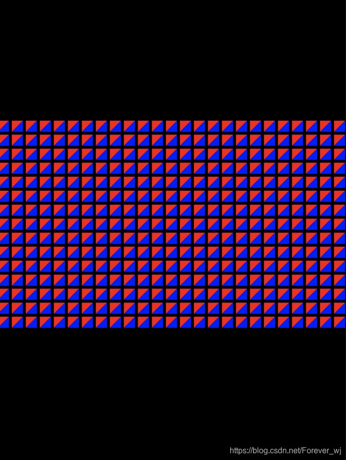
const NSUInteger NUM_COLUMNS = 25;
const NSUInteger NUM_ROWS = 15;
// 顶点个数
const NSUInteger NUM_VERTICES_PER_QUAD = sizeof(quadVertices) / sizeof(CCVertex);
// 四边形间距
const float QUAD_SPACING = 50.0;
// 数据大小 = 单个四边形大小 * 行 * 列
NSUInteger dataSize = sizeof(quadVertices) * NUM_COLUMNS * NUM_ROWS;
// 开辟空间
NSMutableData *vertexData = [[NSMutableData alloc] initWithLength:dataSize];
// 当前四边形
CCVertex * currentQuad = vertexData.mutableBytes;
// 获取顶点坐标(循环计算)
// 行
for(NSUInteger row = 0; row < NUM_ROWS; row++) {
// 列
for(NSUInteger column = 0; column < NUM_COLUMNS; column++) {
// 左上角的位置
vector_float2 upperLeftPosition;
// 计算X,Y 位置.注意坐标系基于2D笛卡尔坐标系,中心点(0,0),所以会出现负数位置
upperLeftPosition.x = ((-((float)NUM_COLUMNS) / 2.0) + column) * QUAD_SPACING + QUAD_SPACING/2.0;
upperLeftPosition.y = ((-((float)NUM_ROWS) / 2.0) + row) * QUAD_SPACING + QUAD_SPACING/2.0;
// 将quadVertices数据复制到currentQuad
memcpy(currentQuad, &quadVertices, sizeof(quadVertices));
// 遍历currentQuad中的数据
for (NSUInteger vertexInQuad = 0; vertexInQuad < NUM_VERTICES_PER_QUAD; vertexInQuad++) {
//修改vertexInQuad中的position
currentQuad[vertexInQuad].position += upperLeftPosition;
}
// 更新索引
currentQuad += 6;
}
}
return vertexData;
}
- 创建命令队列
	// 创建命令队列
    _commandQueue = [_device newCommandQueue];
三、drawInMTKView
主要加载顶点缓冲区数据
- 为当前渲染的每个渲染传递创建一个新的命令缓冲区
 	// 为当前渲染的每个渲染传递创建一个新的命令缓冲区
    id<MTLCommandBuffer> commandBuffer = [_commandQueue commandBuffer];
    // 指定缓存区名称
    commandBuffer.label = @"MyCommand";
- 创建渲染描述符
	MTLRenderPassDescriptor *renderPassDescriptor = view.currentRenderPassDescriptor;
    // 判断渲染目标是否为空
    if(renderPassDescriptor != nil) {
    	// 创建渲染命令编码器,这样才可以渲染到something
        id<MTLRenderCommandEncoder> renderEncoder =
        [commandBuffer renderCommandEncoderWithDescriptor:renderPassDescriptor];
        // 渲染器名称
        renderEncoder.label = @"MyRenderEncoder";
    }
- 设置我们绘制的可绘制区域
	/*设置绘制的可绘制区域
     *
     *typedef struct {
      double originX, originY, width, height, znear, zfar;
      } MTLViewport;
     */
     [renderEncoder setViewport:(MTLViewport){
            0.0, 0.0, _viewportSize.x, _viewportSize.y, -1.0, 1.0
     }];
- 设置渲染管道
	// 设置渲染管道
    [renderEncoder setRenderPipelineState:_pipelineState];
- 为了从OC代码找发送数据预加载的MTLBuffer 到Metal 顶点着色函数中
	// 将_vertexBuffer 设置到顶点缓存区中
    [renderEncoder setVertexBuffer:_vertexBuffer
                                offset:0
                               atIndex:CCVertexInputIndexVertices];

    // 将 _viewportSize 设置到顶点缓存区绑定点设置数据
    [renderEncoder setVertexBytes:&_viewportSize
                               length:sizeof(_viewportSize)
                              atIndex:CCVertexInputIndexViewportSize];
- 开始绘图
	[renderEncoder drawPrimitives:MTLPrimitiveTypeTriangle
                          vertexStart:0
                          vertexCount:_numVertices];
- 结束编码,表示已该编码器生成的命令都已完成,并且从NTLCommandBuffer中分离
[renderEncoder endEncoding];
- 一旦框架缓冲区完成,使用当前可绘制的进度表
[commandBuffer presentDrawable:view.currentDrawable];
- 完成渲染并将命令缓冲区推送到GPU
[commandBuffer commit];
效果展示