入队流程
我们先看看,官网上是怎么说的:
Enqueue Pipeline
The sequence of steps per packet:
Access the mbuf to read the data fields required to identify the destination queue for the packet. These fields are: port, subport, traffic class and queue within traffic class, and are typically set by the classification stage.
Access the queue structure to identify the write location in the queue array. If the queue is full, then the packet is discarded.
Access the queue array location to store the packet (i.e. write the mbuf pointer).
It should be noted the strong data dependency between these steps, as steps 2 and 3 cannot start before the result from steps 1 and 2 becomes available, which prevents the processor out of order execution engine to provide any significant performance optimizations.
Given the high rate of input packets and the large amount of queues, it is expected that the data structures accessed to enqueue the current packet are not present in the L1 or L2 data cache of the current core, thus the above 3 memory accesses would result (on average) in L1 and L2 data cache misses. A number of 3 L1/L2 cache misses per packet is not acceptable for performance reasons.
The workaround is to prefetch the required data structures in advance. The prefetch operation has an execution latency during which the processor should not attempt to access the data structure currently under prefetch, so the processor should execute other work. The only other work available is to execute different stages of the enqueue sequence of operations on other input packets, thus resulting in a pipelined implementation for the enqueue operation.
Fig. 41.6 illustrates a pipelined implementation for the enqueue operation with 4 pipeline stages and each stage executing 2 different input packets. No input packet can be part of more than one pipeline stage at a given time.
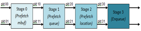
Fig. 41.6 Prefetch Pipeline for the Hierarchical Scheduler Enqueue Operation
The congestion management scheme implemented by the enqueue pipeline described above is very basic: packets are enqueued until a specific queue becomes full, then all the packets destined to the same queue are dropped until packets are consumed (by the dequeue operation). This can be improved by enabling RED/WRED as part of the enqueue pipeline which looks at the queue occupancy and packet priority in order to yield the enqueue/drop decision for a specific packet (as opposed to enqueuing all packets / dropping all packets indiscriminately).
根据上面了解大概的流程,我们来梳理整个入队的过程:
VPP 的work线程把报文入对应接口的Ring队列的时候,需要根据一定的规则分类数据包(FILTER、FLOW、规则),并设置报文需要入队的subport\pipe\tc\queue参数(如何根据分类确定这4个参数,也就是不同的CLASS),并存放在报文描述符的sched字段里面。
然后HQOS线程从Ring队列出队报文,开始真正的QOS入队流程,函数是rte_sched_port_enqueue。

DPDK的QOS入队流程实现了4级流水线,每次流水线同时处理2个报文,除去stage 0获取报文,每次流水线可以处理6个报文,如果入队的报文数不够6个,会走到小于6个报文的处理流程,我们先梳理清楚这个逻辑,在来看后面的流水线实现。

1、预取所有报文的rte_mbuf到L1 Cache。
2、然后每个报文调用rte_sched_port_enqueue_qptrs_prefetch0,完成根据报文携带的sched字段完成subport、pipe、tc、queue值的解析,然后根据这四个值,根据前面的数据结构的关系计算出具体struct rte_sched_queue *queue的qindex,就是前面图里面的q0对应的下标,然后得到具体要入队的queue,同时预取queue。
3、然后每个报文调用rte_sched_port_qbase,根据队列的qindx定位真正入队的基地址
port->queue_array + (qindex >> 4)* port->qsize_sum + port->qsize_add[qindex & 0xF]) 获取存放rte_mbuf指针的指定队列基地址qbase。
获取了qbase后调用rte_sched_port_enqueue_qwa_prefetch0 获取队列大小以及指定的队列写入的位置,然后预取要写入的位置以及qindx对应的位图的位置。
qsize = rte_sched_port_qsize(port, qindex);
q_qw = qbase + (q->qw & (qsize - 1));
4、走完前面的3步终于报文要入真正的队列了,调用函数rte_sched_port_enqueue_qwa完成真正的入队,期间可能被Tail Drop或者被WRED丢弃,如果没有被丢弃,就会真正的入队,并且置位qindex对应的位图,好让dequeue出队报文。
/* Enqueue packet */
qbase[q->qw & (qsize - 1)] = pkt;
q->qw++;
/* Activate queue in the port bitmap */
rte_bitmap_set(port->bmp, qindex);
流水线
如果报文>=6个,就会走到我们4级流水线的流程里面,让我们继续来看
准备工作

为了让4级流水线跑起来,我们需要做准备工作如:

运行流水线

当准备工作完成后,我们开始了真正的流水线处理,整体流程如下,需要和前面的准备工作结合一起看:

收尾工作
如果报文刚好6个或者不是2的倍数,我们需要做收尾的工作如下:


出队流程
我们先看看,官网上是怎么说的出队流程:
Dequeue State Machine
The sequence of steps to schedule the next packet from the current pipe is:
Identify the next active pipe using the bitmap scan operation, prefetch pipe.
Read pipe data structure. Update the credits for the current pipe and its subport. Identify the first active traffic class within the current pipe, select the next queue using WRR, prefetch queue pointers for all the 16 queues of the current pipe.
Read next element from the current WRR queue and prefetch its packet descriptor.
Read the packet length from the packet descriptor (mbuf structure). Based on the packet length and the available credits (of current pipe, pipe traffic class, subport and subport traffic class), take the go/no go scheduling decision for the current packet.
To avoid the cache misses, the above data structures (pipe, queue, queue array, mbufs) are prefetched in advance of being accessed. The strategy of hiding the latency of the prefetch operations is to switch from the current pipe (in grinder A) to another pipe (in grinder B) immediately after a prefetch is issued for the current pipe. This gives enough time to the prefetch operation to complete before the execution switches back to this pipe (in grinder A).
The dequeue pipe state machine exploits the data presence into the processor cache, therefore it tries to send as many packets from the same pipe TC and pipe as possible (up to the available packets and credits) before moving to the next active TC from the same pipe (if any) or to another active pipe.

Fig. 41.7 Pipe Prefetch State Machine for the Hierarchical Scheduler Dequeue Operation
QOS调度就是根据HQOS每个层的调度算法选择一个此时优先级最高的报文来发送。
DPDK在PIPE层是采用轮询的方法调度,也就是WRR 1:1的来调度,也就是说,每个PIPE之间是平等的,没有先后之分,谁准备好了数据谁就发送;
对于同一PIPE中的4个TC,采用SP的调度,对于同一TC下的4个队列,采用的是WRR(比例可配置)的方法。
为了加速内存数据的读取,充分利用cache,DPDK分4个阶段来读取 QOS 队列中的报文,也就是上面说的状态机,流水线,从队列中调度出一个报文用于发送。
出队函数

grinder
为了了解状态机的运行,我们先来认识下grinder。
数据结构如下:

出队状态机的4个阶段中
e_GRINDER_PREFETCH_PIPE,
e_GRINDER_PREFETCH_TC_QUEUE_ARRAYS,
e_GRINDER_PREFETCH_MBUF,
e_GRINDER_READ_MBUF,
前面的一个阶段是为了后面的一个阶段读取数据做内存预取准备工作, 每个阶段都需要等待前一阶段内存准备好后才能执行,由于latency of the prefetch,每个阶段之间就有一个时间空闲,如果CPU连续地执行上面 4 个阶段,则预取内存的效果没有得到体现。为了有效利用CPU,充分利用cache,在操作的时候内存已经在cache里面,dequeue设计了8个grinder,每一个 grinder执行4个阶段的步骤,轮留执行8个grinder,每个grinder只执行一个阶段,这样,可以保证每个grinder阶段执行时,本阶段所要访问的数据已经在缓存中准备好了,相当于实现了入队差不多的流水线。
还有8个grinder分阶段执行的好处还在于实现了各 PIPE之间的随机轮询,谁先准备好数据谁先发送。
图如下:

状态机
PREFETCH_PIPE
这个状态是初始化的状态,主要是函数grinder_next_pipe获取下一个pipe,如果缓存的有的话直接从缓存获取,如果没有的话,scan 队列的qindex位图,一次获取64 bit,从位图中选择下一个active的PIPE(active PIPE指至少有一个队列有报文),并填充grinder里面的pipe缓存,整体流程如下:


PREFETCH_TC_QUEUE_ARRAYS
这个状态的处理比较简单,整体流程如下:

PREFETCH_MBUF
这个流程更简单了,根据前面获取的qbase和队列对应的qr获取报文,此时并同时预取MBUF到cache line,为下一个阶段做好准备。
READ_MBUF
经过前面3个状态的处理,完事具备了,就差最后出队报文,我们来看下这个状态的处理。
从报文描述符中获取报文长度,然后去过令牌桶,如果有足够的令牌,本TC可以发送报文。
如果不能发送,或者TC队列为空,那么需要重新找下一个TC来发送。
如果当前PIPE的所有TC都没有可以发送的报文,则需要重新找一个缓存的PIPE来发送。
如果当前grinder缓存的PIPE也没有可以发送的报文,重新从位图选取一个组新的PIPE cache,然后重新来一轮循环。
整体流程图如下:

queue的WRR实现
在QOS里面FQ或者WFQ队列的WRR算法注重于在时间上调度上的公平性,即完全按照其权值来进行调度,谁的权值大,谁优先。
而本次DPDK的WRR更多的是在空间上考虑公平性,打散整个结果,而考虑其处于的位置也许是最好的方案,让我们一起看下整个处理的过程:
初始化的时候根据传入的队列的weight[0 .. 3]的比例,根据最小公倍数计算每个队列的cost,然后保存在wrr_cost[0..3]里面,也就是权重越大的cost越小,如weight[0..3]={2:3:4:5},那么wrr_cost[0..3]={30:20:15:12}
在grinder选中新的TC调度的时候,会调用grinder_wrr_load初始化grinder的WRR参数,wrr_tokens初始化为0,wrr_mask如果有队列初始化为0xFFFF,否则初始化为0, wrr_cost初始化为前面计算的cost值
调度的时候调用grinder_wrr每次选中需要调度出队的队列,代码如下:

经过第一步操作后,如果有激活的队列wrr_tokens变成0,否则值变成0xFFFF。
第二步,选择4个队列中,wrr_tokens最小的,也就是本次需要出队的队列
第三步,所有队列的wrr_tockens减去最小的wrr_tockes_min
那么如何证明算法的正确性,我们先假设4个队列的报文长度相等
假设有3个具有不同weight的{A:a,B:b,C:c}元素供选择,cost值分别为{A:b*c,B:a*c,C:a*b}在一轮循环a+b+c中,3个元素被选中的次数为x\y\z,那么
x + y + z = a + b +c
A的tokens新增 x*b*c
B的tokens新增 y*a*c
C的tokens新增 z*a*b
然后每次循环选择tokens最小的队列,所有的队列都要减去这个值,那么问题转化为,每个元素一轮递增的tokens量中有多少个其它元素的个数。
x = x*b*c / (y*a*c + z*a*b)
y = y*a*c / (x*b*c + z*a*b)
z = z*a*b / (y*a*c + z*b*c)
解方程后可知,x = a, y = b, z = c
个人觉得有点绕,何不直接使用weight,不选最小的,选择最大的即可。
目前的这个实现有下面的几个问题:
- 如果报文长度不相等,也就实现不了按比例调度了
- 如果报文长度相等才实现按比例调度,也就没有实现按照字节的比例调度,这个可以作为后期的一个改进,但目前在叶子节点的问题不大
PIPE的WRR调度
PIPE 本次是放在8个grinder里面调度的,谁有报文谁先发送,也可以简单理解为WRR为1:1的调度,暂不考虑PIPE之间的如WRR[1:2:3………]的调度。
基于类的保证带宽(限制带宽)实现
经过上面的分析我们知道当前DPDK的QOS所有的PIPE是按照WRR调度,谁准备好谁就发送,PIPE下面的TC是SP调度,满足不了CBWFQ里面保证带宽的需求。
要实现CBWFQ的保证带宽和限制带宽,需要修改DPDK QOS的代码,后续实现后,在分析
