This is the last article in the series, we will finish this lab with the VXLAN configuration and testing connectivity between servers.
VIRTUAL EXTENSIBLE LAN (VXLAN)
The VXLAN protocol is an RFC (7348). The standard defines a MAC in IP encapsulation protocol allowing the construction of Layer-2 domains across a Layer-3 IP infrastructure. The protocol is typically deployed as a data center technology to create overlay networks across a transparent Layer-3 infrastructure:
- Providing Layer-2 connectivity between racks or PODs without requiring an underlying Layer-2 infrastructure
- Logical connecting geographically disperse data centers at Layer-2 as a data center Interconnect (DCI) technology
- VLAN supports up to 16 million virtual overlay tunnels over a physical Layer-2/3 underlay network for Layer-2 network connectivity and multi-tenancy
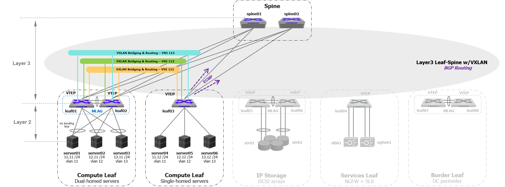 Two-tier Layer-3 VXLAN Ethernet Fabric
VXLAN encapsulation/decapsulation is performed by a VXLAN Tunnel End Point (VTEP), this can be either:
- A VXLAN-enabled hypervisor such as ESXi, KVM, or XEN (software VTEP)
- A network switch (hardware VTEP)
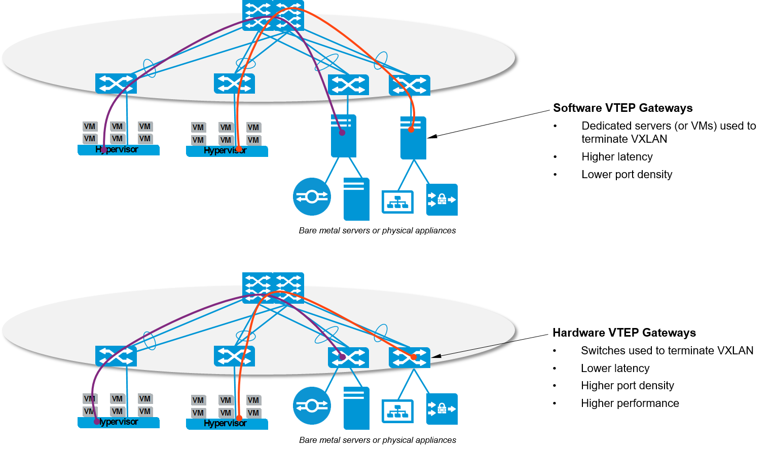 Software & Hardware VTEPs
To create VXLAN overlay virtual networks, IP connectivity is required between VTEPs.
VXLAN CONTROL PLANE
When VXLAN was released, the IETF defined the VXLAN standards (RFC 7348) with a multicast-based flood&learn mechanism that acts as a really complex control plane. It was evident the RFC was incomplete (to say the least) as flooding multicast-based VXLAN in the underlay represented several challenges in the data center including scalability and complexity.
To overcome these limitations, networking vendors started to introduce control plane technologies to replace the multicast-based flooding.
Depending on the vendor, you can have more than one option to deploy a VXLAN control plane solution. To simplify things, it’s a good idea to categorize these technologies:
- Network-centric vs Hypervisor-based
- Head End Replication vs Dynamic tunnel
Network-centric vs Hypervisor-based solutions
The VXLAN control plane process implies the creation of VXLAN tables that contain the VNI/VLAN mapping information, remote MAC Addresses available per VTEP, and the VTEP/Hypervisor IP Address to establish the VXLAN tunnels.
Some networking vendors have control plane solutions based on SDN that leave the control plane process to an external software layer called Controller. The SDN Controller is responsible for replicating, synchronizing and maintaining the VXLAN tables on the Hypervisors, among other tasks. In order for the Hypervisors to speak with the Controller, VXLAN agents are installed either as part of the host kernel or as a VM inside the Hypervisor on each compute node; the agents (called VTEPs) receive the VXLAN information from the Controller so they can encapsulate/decapsulate traffic based on the instructions contained in the tables.
The use of an SDN Controller as a VXLAN control plane solution is just one option. An alternative is to deploy the VXLAN control plan directly on the Ethernet Fabric. This network-centric solution requires the Ethernet Fabric to be VXLAN-capable meaning the data center switches have to support VXLAN. In the Hypervisor-based solution, the underlay is not aware of the overlay network so the switches do not need to support VXLAN.
NOTE: Since the VXLAN data/control planes are not standardized among vendors, you should expect to find some incompatibility in a multi-vendor network.
Head End Replication vs Dynamic Tunnels Setup
If you want to deploy the VXLAN control plane on the underlay, we need to decide on how to setup the VXLAN tunnels.
VXLAN tunnels can be setup manually (Head End Replication) or dynamically (MP-BGP EVPN). Head End Replication (HER) is the static mappings of VTEPS for the management of broadcast, unicast, multicast, and unknown packets. It requires to configure each switch with the VNI/VLAN mappings and the list of VTEPs to share MAC addresses and forward BUM traffic. This options works well for small and medium-sized networks. However, scalability and human errors are the primary concerns for large networks.
To automate and simplify the VXLAN tunnels setup, Multi-Protocol Border Gateway Protocol Ethernet VPN (MP-BGP EVPN) is used as a routing protocol to coordinate the creation of dynamic tunnels. EVPN is an extension to the MP-BGP address family which allows to carry VXLAN/MAC information in the BGP routing updates.
VXLAN ROUTING AND BRIDGING
The deployment of VXLAN bridging provides Layer-2 connectivity across the Layer-3 Leaf-Spine underlay for hosts. To provide Layer-3 connectivity between the hosts VXLAN routing is required.
VXLAN routing, sometimes referred to as inter-VXLAN routing, provides IP routing between VXLAN VNIs in the overlay network. VXLAN routing involves the routing of traffic based, not on the destination IP address of the outer VXLAN header but the inner header or overlay tenant IP address.
VXLAN Routing Topologies
The introduction of VXLAN routing into the overlay network can be achieved by a direct or indirect routing model:
- Direct Routing: The direct routing model provides routing at the first-hop Leaf node for all subnets within the overlay network. This ensures optimal routing of the overlay traffic at the first hop Leaf switch
- Indirect Routing: To reduce the amount of state (ARP /MAC entries and routes) each Leaf node holds, the Leaf nodes only route for a subset of the subnets
The Direct Routing model works by creating anycast IP addresses for the host subnets across each of the Leaf nodes, providing a logical distributed router. Each Leaf node acts as the default gateway for all the overlay subnets, allowing the VXLAN routing to always occur at the first-hop.
CONFIGURING VXLAN
For this lab, I’m going to use Direct Routing and Head End Replication (HER) to setup the VXLAN tunnel. In later posts, I will add a couple of SDN Controllers to demonstrate the centralized VXLAN control plane option with VXLAN agents on the compute nodes.
NOTE: As of the writing of this article, EVPN is not supported on vEOS. In fact, Arista just announced EVPN support on the latest EOS release, so it’s still a work in progress.
To provide direct routing, the Leaf nodes of the MLAG domain were configured with an IP interface for every subnet. I already covered this part in my previous post: I configured VARP with the “ip virtual router” representing the default gateway for the subnet.
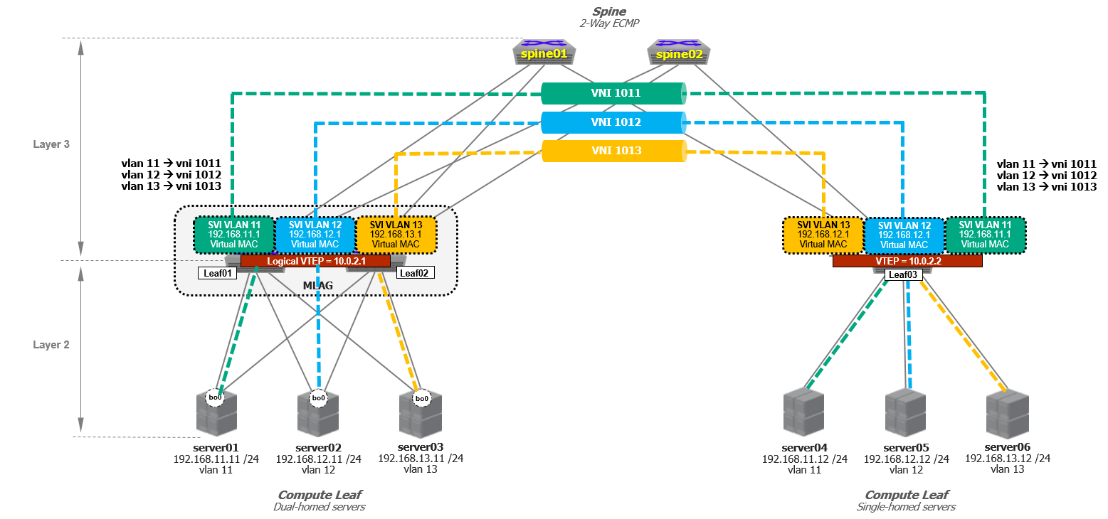
 VXLAN Routing with MLAG
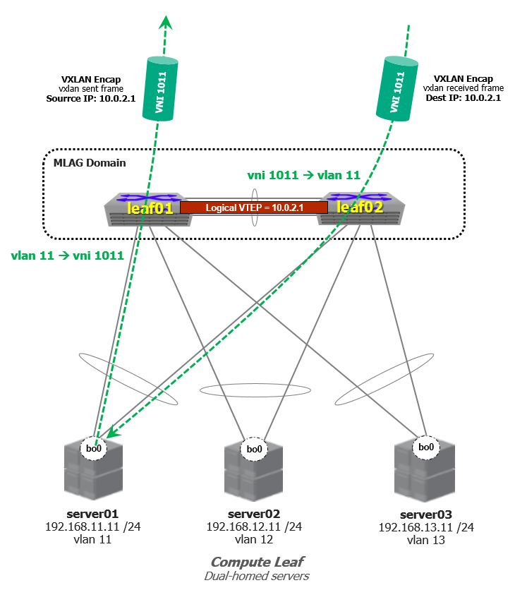
On the other hand, Layer-2 connectivity between racks will be achieved by configuring a VXLAN VTEP on the Leaf switches. For the Dual-homed Compute Leaf, a single logical VTEP is required for the MLAG domain. We need to configure the VTEP on both MLAG peers with the same Virtual Tunnel Interface (VTI) IP address, this ensures both peers decapsulate traffic destined to the same IP address.
The logical VTEP in combination with MLAG provides an active-active VXLAN topology.
 VXLAN Overlay Networks
The logical VTEP address is configured as a new loopback interface. This IP address will be used as the VXLAN tunnel source interface.
Let’s configure the Loopback1 interface, we need to configure the same IP address on the MLAG peers.
hostname leaf01
 !
 interface loopback1
 ip address 10.0.2.1/32
 !
hostname leaf02
 !
 interface loopback1
 ip address 10.0.2.1/32
 !
hostname leaf03
 !
 interface loopback1
 ip address 10.0.2.2/32
 !
Next, we need to assign Loopback1 to the VXLAN tunnel interface (VTI).
hostname leaf01
 !
 interface vxlan1
 vxlan source-interface loopback1
 !
hostname leaf02
 !
 interface vxlan1
 vxlan source-interface loopback1
 !
hostname leaf03
 !
 interface vxlan1
 vxlan source-interface loopback1
 !
To map the hosts VLANs to the VNIs, I will use the following mapping:
vlan 11 –> vni 1011
vlan 12 –> vni 1012
vlan 13 –> vni 1013
hostname leaf01
 !
 interface vxlan1
 vxlan source-interface loopback1
 vxlan vlan11 vni 1011
 vxlan vlan 12 vni 1012
 vxlan vlan 13 vni 1013
 !
hostname leaf02
 !
 interface vxlan1
 vxlan source-interface loopback1
 vxlan vlan11 vni 1011
 vxlan vlan 12 vni 1012
 vxlan vlan 13 vni 1013
 !
hostname leaf03
 !
 interface vxlan1
 vxlan source-interface loopback1
 vxlan vlan11 vni 1011
 vxlan vlan 12 vni 1012
 vxlan vlan 13 vni 1013
 !
Now we have to configure the flood list for the VNIs so the VTEPs can send BUM traffic and learn MAC address between them.
hostname leaf01
 !
 interface vxlan1
 vxlan source-interface loopback1
 vxlan vlan11 vni 1011
 vxlan vlan 12 vni 1012
 vxlan vlan 13 vni 1013
 vxlan vlan11 flood vtep 10.0.2.2
 vxlan vlan12 flood vtep 10.0.2.2
 vxlan vlan13 flood vtep 10.0.2.2
 !
hostname leaf02
 !
 interface vxlan1
 vxlan source-interface loopback1
 vxlan vlan11 vni 1011
 vxlan vlan 12 vni 1012
 vxlan vlan 13 vni 1013
 vxlan vlan11 flood vtep 10.0.2.2
 vxlan vlan12 flood vtep 10.0.2.2
 vxlan vlan13 flood vtep 10.0.2.2
 !
hostname leaf03
 !
 interface vxlan1
 vxlan source-interface loopback1
 vxlan vlan11 vni 1011
 vxlan vlan 12 vni 1012
 vxlan vlan 13 vni 1013
 vxlan vlan11 flood vtep 10.0.2.1
 vxlan vlan12 flood vtep 10.0.2.1
 vxlan vlan13 flood vtep 10.0.2.1
 !
Finally, to provide IP connectivity between the VTEPs, the loopback IP address of the VTIs need to be advertised into BGP. We just need to announce the logical VTEP IP address into BGP when a new VTEP is added to the topology.
hostname leaf01
!
router bgp 65021
network 10.0.2.1/32
!
hostname leaf02
!
router bgp 65021
network 10.0.2.1/32
!
hostname leaf03
!
router bgp 65022
network 10.0.2.2/32
!
With the Leaf switches announcing their respective VTEP into the underlay BGP routing topology, each Leaf switch learns two equal cost paths (via the Spine switches) to the remote VTEP.
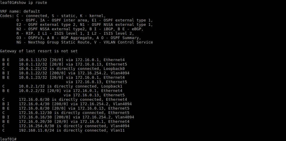
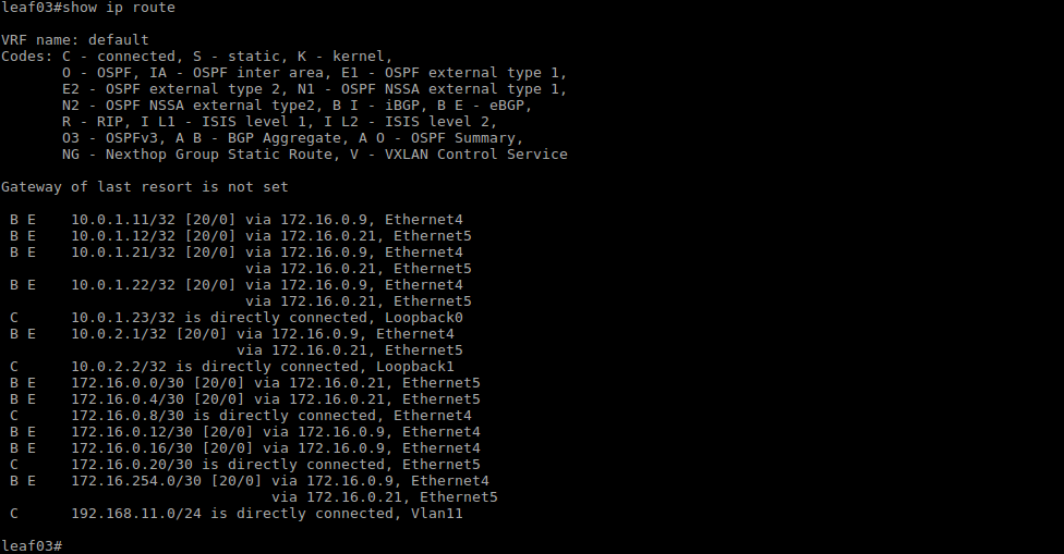
With the direct routing model, the host subnets exist only on the Leaf switches, there is no need to announce them into BGP; the Spine switches are transparent to the overlay subnets, they only learn the VTEP addresses.
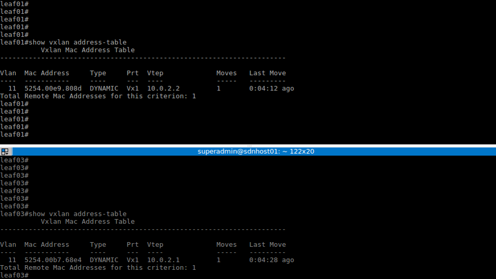
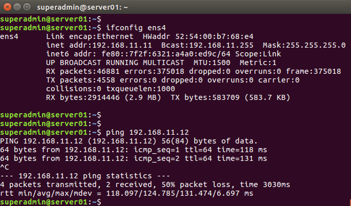
Layer-2 and Layer-3 connectivity between the servers is now possible. Below is the resultant MAC and VXLAN address table for the Leaf switches and the ping results between servers.

You can always check my github repository to download the configuration files.