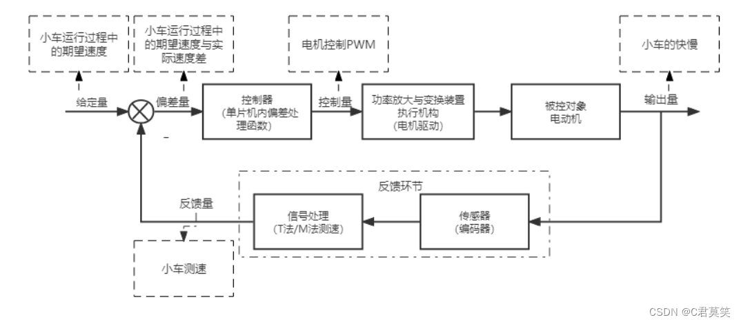
Smart car based on STM32
Chapter 1 Design of Smart Car Scheme Based on STM32
Smart car based on STM32--motor drive design
foreword
This article mainly discusses the motor design used in the process of making a smart car on a certain treasure, and provides a reference for everyone.
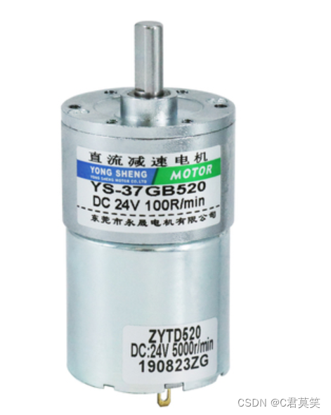
1. What is a motor?
Motors is a device that converts electrical energy into mechanical energy. It is made by using the phenomenon of energized coils rotating under force in a magnetic field. It is distributed at each user. Motors are divided into DC motors and AC motors according to different power sources. There is a wide range of power available, from milliwatts to gigawatts. The use and control of the motor is very convenient, and it has the capabilities of self-starting, acceleration, braking, reversing, and stopping.
Two, common motor classification
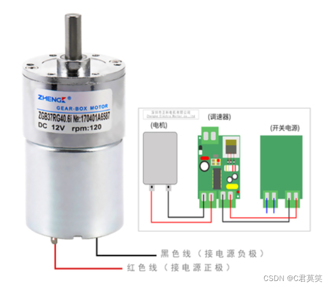
1. Brushed motor
- Brushed motor: A brushed motor is a rotating electrical machine that converts electrical energy into mechanical energy (motor) or converts mechanical energy into electrical energy (generator) with a built-in brush device. Unlike brushless motors, brush devices are used to introduce or extract voltage and current. The brushed motor is the basis of all motors. It has the characteristics of fast starting, timely braking, smooth speed regulation in a wide range, and relatively simple control circuit.
- The brushed motor is the first type of motor that everyone comes into contact with. The motor was introduced as a model in the physics class in middle school. The main structure of the brushed motor is the stator + rotor + brush, which obtains the rotational torque through the rotating magnetic field, thereby outputting kinetic energy. The brushes are constantly in contact and friction with the commutator, and play the role of conduction and commutation during rotation.

2. Brushless motor
- Brushless motor: The brushless DC motor consists of a motor body and a driver, and is a typical mechatronic product.
- In the brushless motor, the commutation work is completed by the control circuit in the controller (usually Hall sensor + controller, more advanced technology is magnetic encoder).

Second, the difference between brushed motor and brushless motor in speed regulation
In fact, the control of the two motors is voltage regulation, but because the brushless DC adopts electronic commutation, it can only be realized with digital control, while the brushed DC is commutated through carbon brushes, using thyristors, etc. Traditional analog circuits can be controlled, which is relatively simple.
1. The speed regulation process of the brushed motor is to adjust the voltage of the motor power supply. The adjusted voltage and current are converted through the commutator and the brush to change the strength of the magnetic field generated by the electrodes to achieve the purpose of changing the rotational speed. This process is called variable speed regulation.
2. The speed regulation process of the brushless motor is that the voltage of the power supply of the motor remains unchanged, the control signal of the ESC is changed, and the switching rate of the high-power MOS tube is changed by the microprocessor to realize the change of the speed. This process is called variable frequency speed regulation.
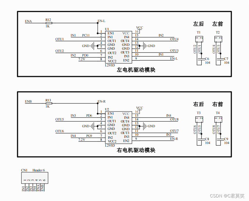
3. Introduction of motor chip
1. L293D chip
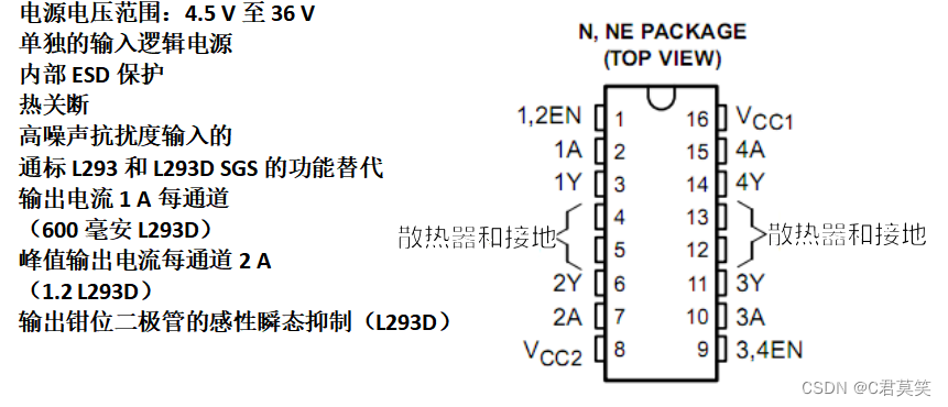
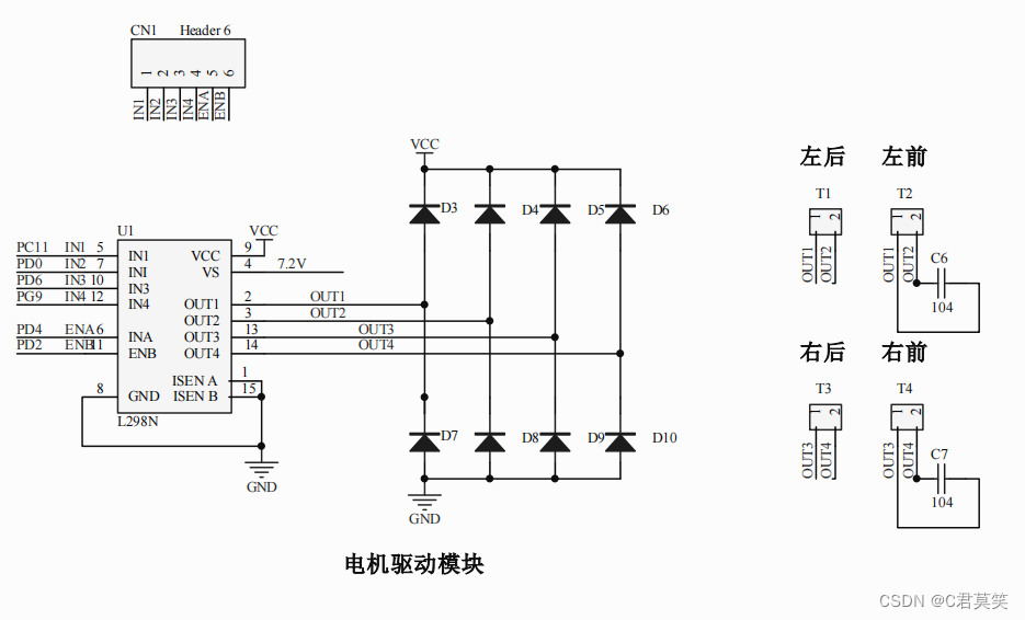
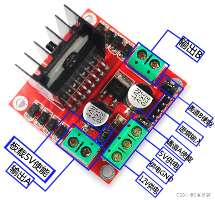
2. L298N chip
The L298N drive module can drive 2 DC motors, which can realize forward and reverse functions respectively.
- With signal indication.
- Adjustable speed
- Strong anti-interference ability
- With overvoltage and overcurrent protection
- Two DC motors can be controlled independently
- A single stepper motor can be controlled
- PWM pulse width smooth speed regulation
- Can realize forward and reverse
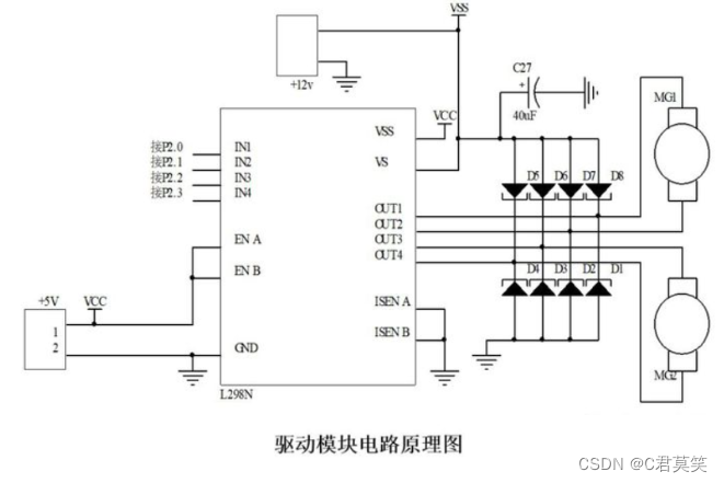
Fourth, the control example of DC motor
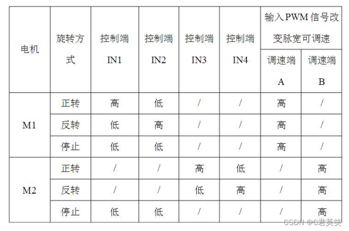
Two DC motors can be driven using a DC/stepper driver. M1 and M2 respectively. Pins A and B can be used to input PWM pulse width modulation signals to control the speed of the motor. (If there is no need to adjust the speed, you can connect the two pins to 5V to make the motor work at the highest speed, and short-circuit the shorting cap.) It is easier to realize the forward and reverse rotation of the motor. The input signal terminal IN1 is connected to the high-level input terminal IN2 Connected to low level, the motor M1 rotates forward. (If the signal terminal IN1 is connected to a low level, and IN2 is connected to a high level, the motor M1 is reversed.) It is the same way to control another motor. The input signal terminal IN3 is connected to a high level, and the input terminal IN4 is connected to a low level. M2 is rotating forward. (The reverse is reversed), PWM signal terminal A controls M1 speed regulation, PWM signal terminal B controls M2 speed regulation.
Five, software-driven code writing
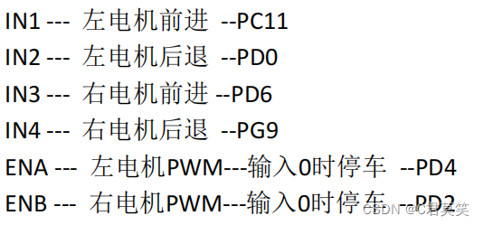
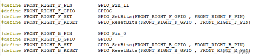
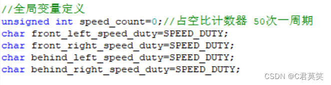
Motor drive IO definition – right motor enable IO as an example
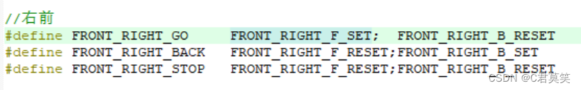
- Related pin macro definition
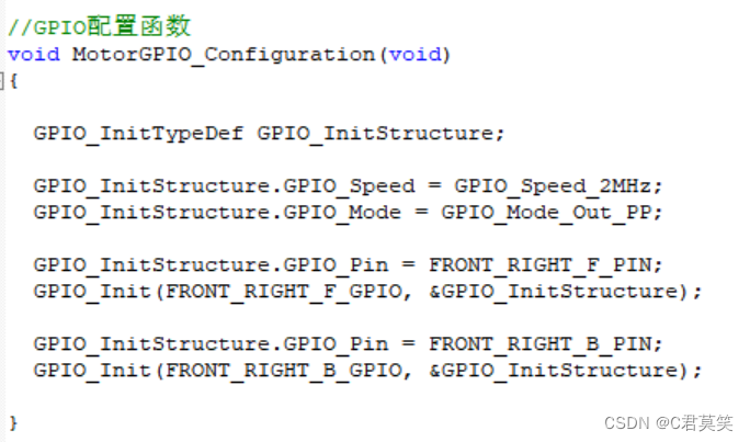
- GPIO initialization
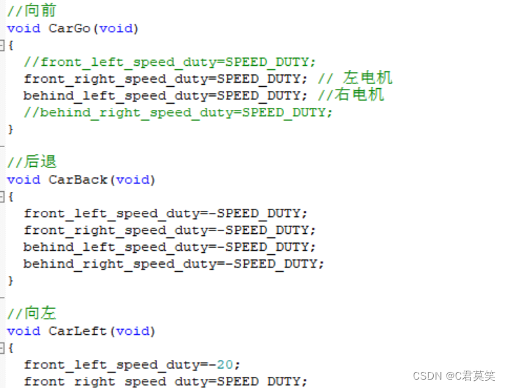
- motor movement
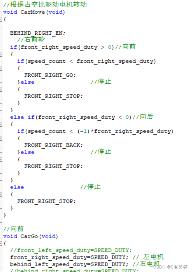
- direction control
Summarize
The introduction of motor control based on STM32 smart car is here