Article directory
- foreword
- 1. Integrate actual project equipment automation resources
- 2. The device enters the cloud physical medium
- 3. The actual project operation process of FlexManager
-
- Step 1 FStudio touch screen programming software operation
- Step 2 FlexManager mounts the serial number of the remote module
- Step 3 Data source configuration to create data group
- Step 4 Add equipment operating parameter points
- Step 5 Add device parameter setting points
- Step 6 Add equipment pump valve status points
- Step 7 Add remote manual point of equipment
- Step 8 Device alarm point registration
- Step 9 Register historical data points of equipment
- Step 10 Device remote operation and maintenance VPN connection
- Step 11 Device touch screen cloud modification
- Step 12 On-site and cloud APP effects
- Summarize
foreword
The last article introduced the operation of FlexCloud cloud data transfer HTTP interface, I believe everyone has read it. At the beginning of this article, the actual project operation process of the actual project equipment into the cloud will be introduced one by one. Of course, you must have a basic grasp of equipment flow charts and some related knowledge of PLC automation. If you are interested, you can go to the column of my PLC programming learning materials to learn a wave, and I will not focus on it here. This article focuses on the specific operation of the actual project operation process of the device entering the cloud.
提示:以下是本篇文章正文内容,下面案例可供参考
1. Integrate actual project equipment automation resources
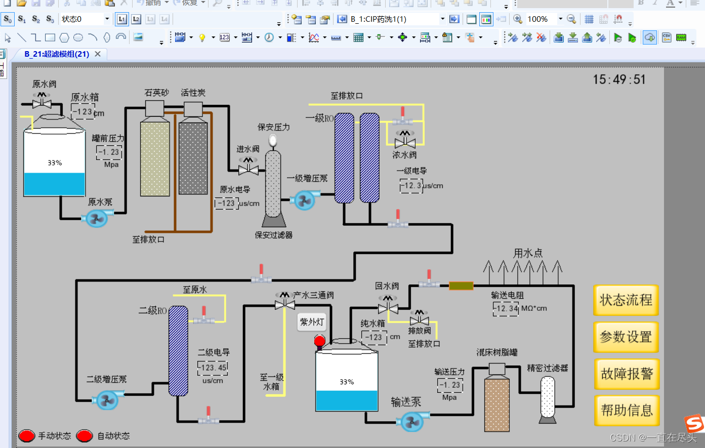
In the initial stage of the equipment entering the cloud, it is particularly important to integrate the actual project equipment automation resources. Among them, focus on mastering the flow chart of the equipment, the control logic, the point deployment of the controller, and the main performance parameters.
1. Equipment flow chart
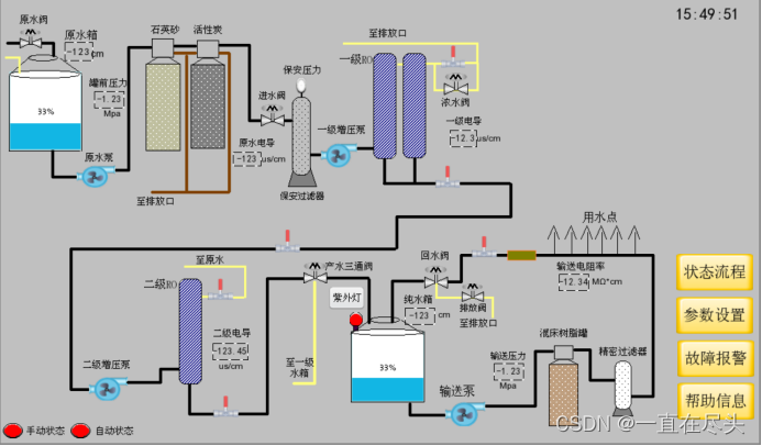
2. Process control logic
2.1 Raw water tank inlet control logic:
Raw water tank liquid level < raw water tank liquid level → raw water inlet valve open;
raw water tank liquid level > raw water tank high liquid level → raw water inlet valve closed;
2.2 Preprocessing RO system control logic:
Raw water tank liquid level >= raw water tank liquid level → pure water tank liquid level < pure water tank liquid level → multi-media filter signal → activated carbon filter signal → primary low pressure switch is normal → primary high pressure switch is normal → secondary high pressure switch Normal → water leakage alarm signal is normal → secondary high pressure switch is normal → pretreatment RO system water generation is executed;
pretreatment RO system water generation execution: primary water inlet valve open → primary concentrated water valve open (according to the set time) → original Pump on → primary concentrated water valve off → primary booster pump on → secondary product water return water timing on → secondary product water valve off → secondary booster pump on;
raw water tank liquid level < raw water tank low liquid level →Pretreatment RO system water production stopped;
pure water tank liquid level > pure water tank high liquid level → pretreatment RO system water production stopped;
raw water pump alarm → pretreatment RO system water production stopped;
primary booster pump alarm → pretreatment Processing RO system water production stop;
secondary booster pump alarm → pretreatment RO system water production stop;
primary low pressure switch alarm → pretreatment RO system water production stop;
primary high pressure switch alarm → pretreatment RO system water production stop;
Secondary high pressure switch alarm → pretreatment RO system water production stopped;
water leakage alarm → pretreatment RO system water production stopped;
Multi-media cleaning signal → pretreatment RO system water generation stop → pretreatment multi-media cleaning execution;
activated carbon cleaning signal → pretreatment RO system water generation stop → pretreatment activated carbon cleaning execution;
2.3 Pretreatment RO pump valve switch
Pretreatment RO automatically opens: raw water valve automatic inlet valve + first-stage water inlet valve automatic + first-stage concentrated water valve automatic + second-stage water production valve automatic + raw water pump automatic + first-stage booster pump automatic + second-stage booster pump Automatic;
pretreatment RO manual opening: raw water valve inlet valve manual + primary water inlet valve manual + raw water pump manual + primary booster pump manual + secondary booster pump manual;
2.4 Immersion Sterilization Control Logic
Pure water tank liquid level >= pure water tank liquid level → immersion UV lamp irradiation execution;
pure water tank liquid level < pure water tank low liquid level → immersion UV lamp irradiation stops;
2.5 Conveyor system control logic
The level of pure water tank >= the liquid level in the pure water tank → the alarm signal of the delivery pump is normal → the delivery system executes; the
delivery system executes → the difference between the delivery pressure and the delivery pressure setting value changes the delivery pump frequency → (return resistance > 1MΩ) The return water qualified valve is opened → the delivery pump is started; the
delivery system is executed → the difference between the delivery pressure and the delivery pressure setting value changes the frequency of the delivery pump → (return resistance <1MΩ) the return water unqualified valve is opened → the delivery pump is started;
pure water tank Liquid level < low liquid level of pure water tank → stop of conveying system;
alarm of conveying pump → stop of conveying system;
3. Controller PLC point details
| `Digital input point name | address |
|---|---|
| emergency stop | I0.0 |
| manual | I0.1 |
| automatic | I0.2 |
| Multimedia | I0.3 |
| activated carbon | I0.4 |
| water leak alarm | I0.5 |
| Raw water pump alarm | I0.6 |
| Primary pump alarm | I0.7 |
| Secondary pump alarm | I1.0 |
| Transfer Pump Alarm | I1.1 |
| Primary low voltage switch | I1.2 |
| Primary high voltage switch | I1.3 |
| Secondary high voltage switch | I1.4 |
| `Digital output point name | address |
|---|---|
| Raw water valve | Q0.0 |
| Primary inlet valve | Q0.1 |
| Primary concentrated water valve | Q0.2 |
| Secondary water production valve | Q0.3 |
| immersion sterilization | Q0.4 |
| Return water qualified valve | Q0.5 |
| Return water unqualified valve | Q0.6 |
| Raw water pump | Q0.7 |
| First stage booster pump | Q1.0 |
| Secondary booster pump | Q1.1 |
| Pump | Q1.2 |
| wind scattered | Q1.3 |
| buzzer | Q1.4 |
| Auxiliary manual point name | address |
|---|---|
| Raw water valve manual | M0.0 |
| One-stage water inlet valve manual | M0.1 |
| Manual concentrate valve | M0.2 |
| Manual secondary production water qualified valve | M0.3 |
| immersion sterilizationmanual | M0.4 |
| Manual return valve | M0.5 |
| Return water unqualified valve manual | M0.6 |
| Raw water pump manual | M0.7 |
| Manual first stage pump | M1.0 |
| Manual secondary booster pump | M1.1 |
| Manual transfer pump | M1.2 |
| manual wind blower | M1.3 |
| Buzzer Manual | M1.4 |
| Auxiliary automatic point name | address |
|---|---|
| Raw water valve automatic | M3.0 |
| One-stage water inlet valve automatic | M3.1 |
| Level 1 concentrated water valve automatic | M3.2 |
| Automatic secondary production water qualified valve | M3.3 |
| immersion sterilizationautomatic | M3.4 |
| Automatic return valve | M3.5 |
| Return water unqualified valve automatically | M3.6 |
| Raw water pump automatic | M3.7 |
| Primary pump automatic | M4.0 |
| Secondary booster pump automatic | M4.1 |
| transfer pump automatic | M4.2 |
| wind dispersion automatic | M4.3 |
| Buzzer Automatic | M4.4 |
4. Main performance indicators
| Auxiliary automatic point name | address |
|---|---|
| Manual state | S0.1 |
| automatic state | S0.2 |
| Raw water tank level | VD1000 |
| Pure water tank level | VD1004 |
| Tank front pressure | VD1008 |
| delivery pressure | VD1012 |
| Raw water conductance | VD1016 |
| first order conductance | VD1020 |
| secondary conductance | VD1024 |
| 回水电阻 | VD1028 |
5、主要调节参数
| 辅助自动点位名称 | 地址 |
|---|---|
| 原水低液位 | VD1200 |
| 原水中液位 | VD1204 |
| 原水高液位 | VD1208 |
| 纯水低液位 | VD1212 |
| 纯水中液位 | VD1216 |
| 纯水高液位 | VD1220 |
| 输送压力设定值 | VD1224 |
| 回水合格设定值 | VD1228 |
| 双极RO开关 | VW400 |
| 输送开关 | VW402 |
| 紫外灯开关 | VW404 |
| 回水排放开关 | VW406 |
| 一级浓水排放时间 | VW408 |
| 二级产水排放时间 | VW410 |
| 紫外照射时长 | VW412 |
二、设备入云物理媒介
设备入云物理媒介作为设备与云端的通讯桥梁和纽带,非常值得研究一下。本项目案例采用触摸屏挂载远程通讯模块的方式,最后实现了PLC和触摸屏都能进行云端远程操作。
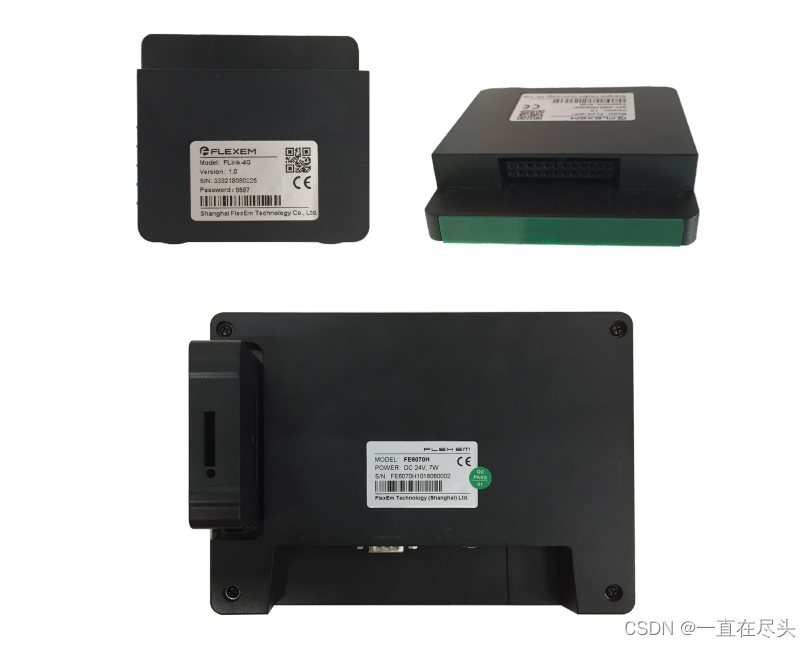
1、带远程触摸屏
繁易工业电阻触摸屏 6000 系列
型号:FE6100W
产品概览
繁易工业触摸屏 6000 系列,新一代物联网人机界面。延续了繁易触摸屏 4000 系列高性价比,
工业 ABS 塑料外壳,低成本,高可靠;全新开模,采用更加实用的向下出线方式;重新设计的前
脸,拥有更高的颜值;有更高分辨率机型可选。
通过选配 FLink 物联网模块,可以立即升级为物联网人机界面,享受完整的繁易工业物联网云
平台服务。
产品外观

2、远程模块
繁易 6000 系列 HMI 物联网扩展模块
FLink 系列
Product Overview
FLink series expansion modules are FE6000 series IoT HMI accessories launched by Fanyi. By adding this accessory,
the traditional FE6000 series HMI can be turned into an IoT HMI supporting remote monitoring functions. It can easily realize
remote data monitoring, remote download program and remote maintenance of on-site PLC and HMI. It supports a variety of Internet access methods, and supports a complete series of FANYI IoT cloud
service products.
This product does not contain a power supply and cannot work independently. It must be used in conjunction with the FE6000 series HMI. When using, you need
to insert the FLink module into the IoT expansion slot on the back of the HMI.
3. The actual project operation process of FlexManager
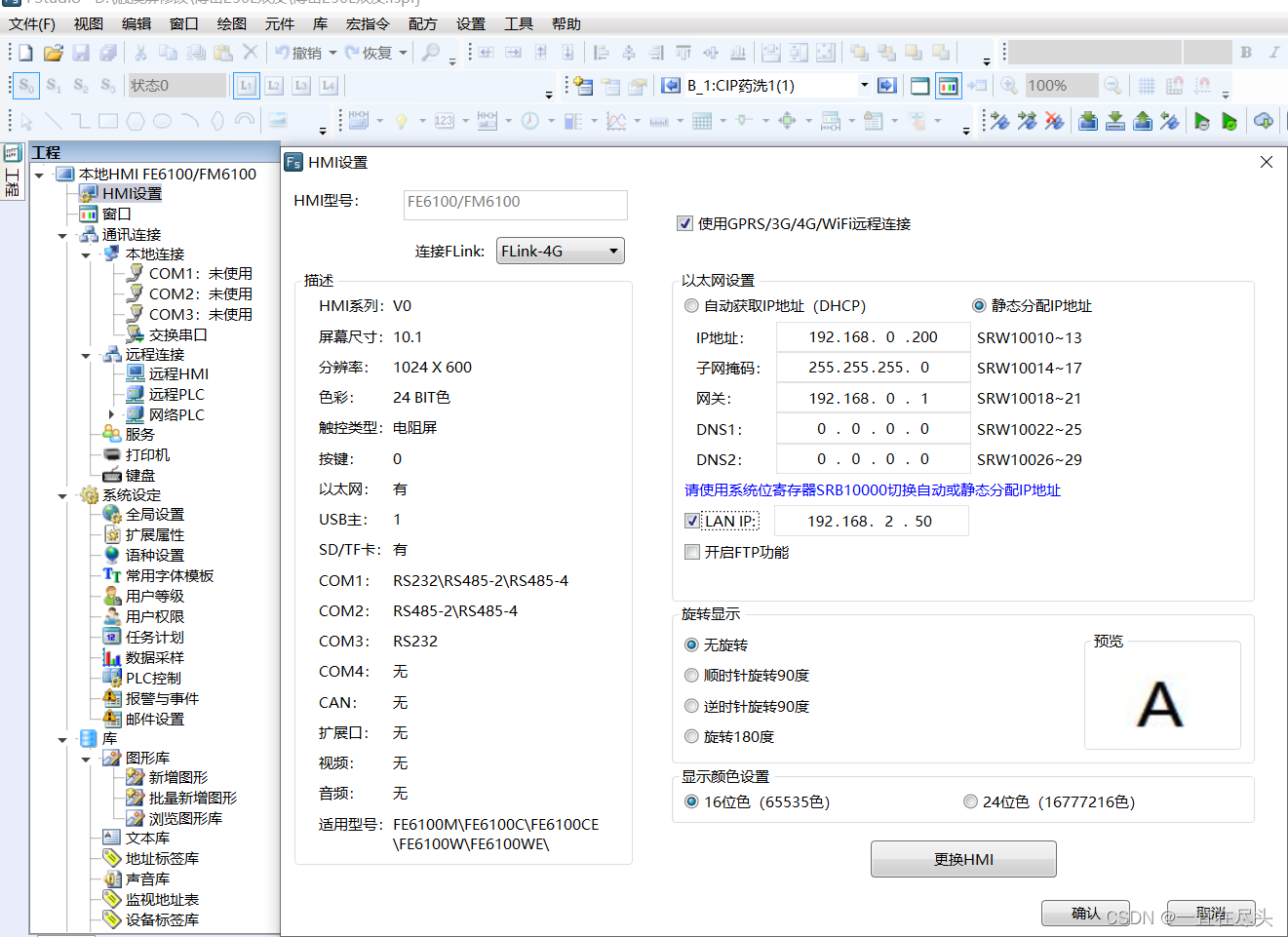
Step 1 FStudio touch screen programming software operation
Mount the flink-4G remote module
as the picture shows:
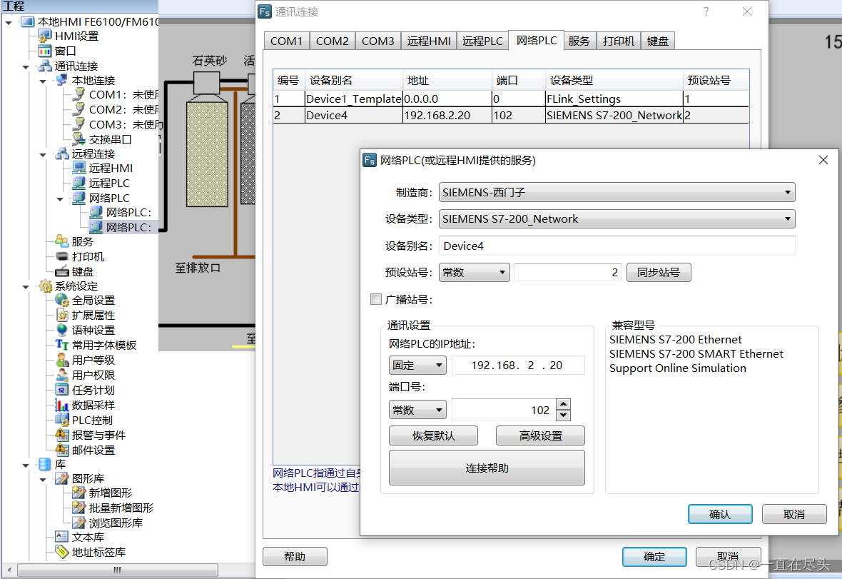
Mount Siemens smart PLC communication driver
as the picture shows:
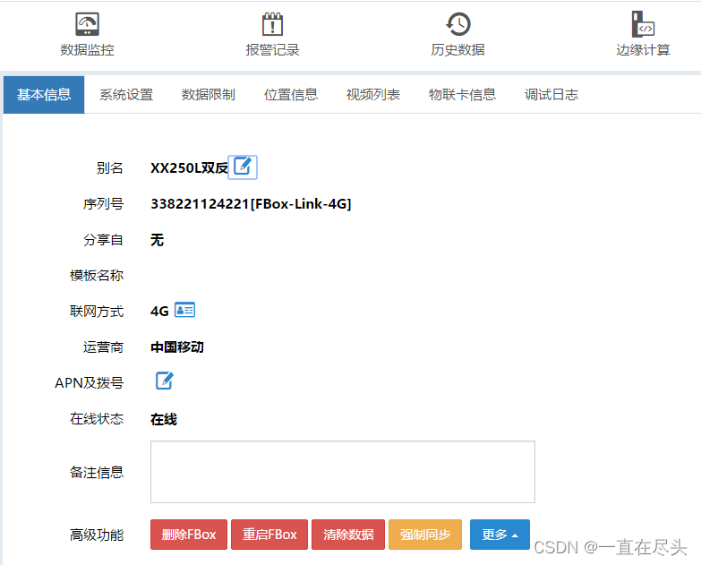
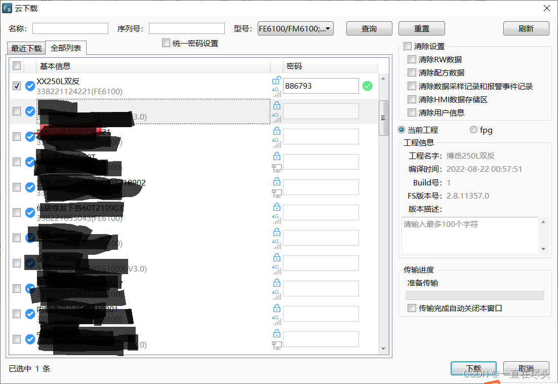
Step 2 FlexManager mounts the serial number of the remote module
as the picture shows:

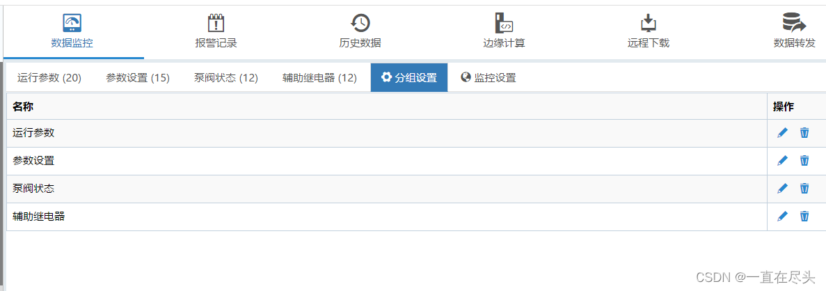
Step 3 Data source configuration to create data group
as the picture shows:
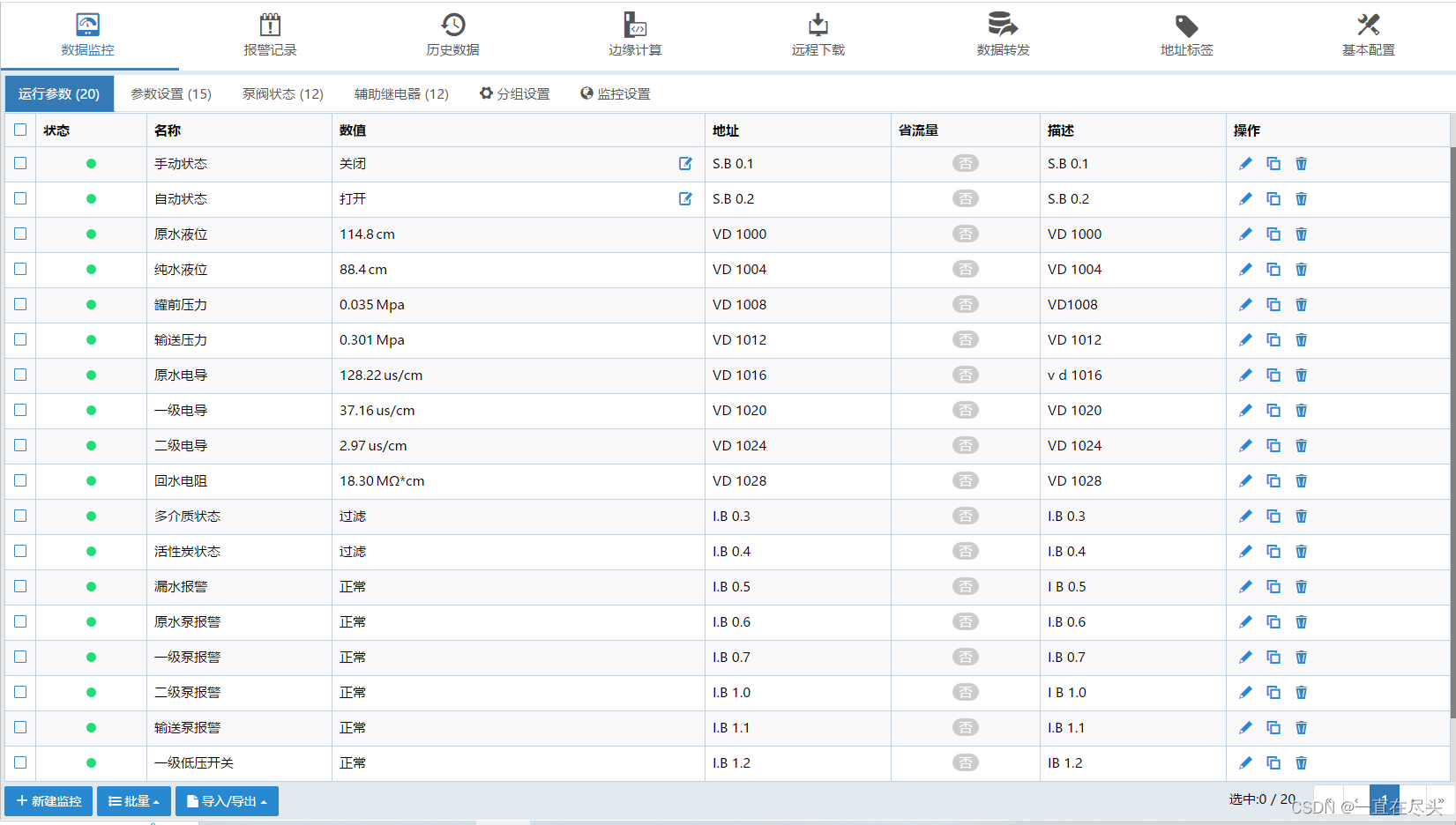
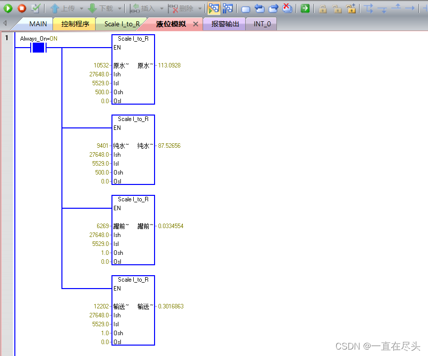
Step 4 Add equipment operating parameter points
as the picture shows:
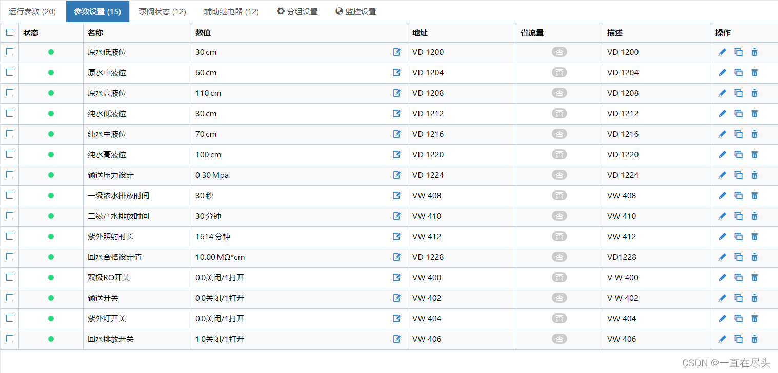
Step 5 Add device parameter setting points
as the picture shows:
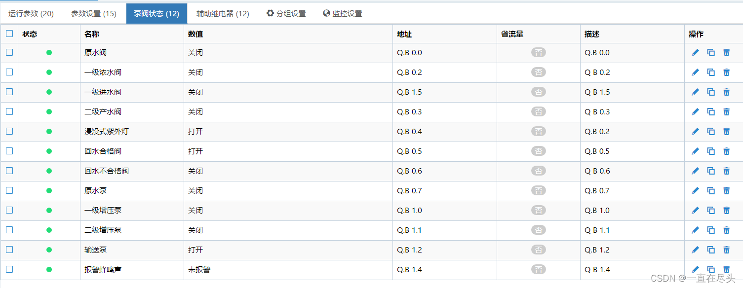
Step 6 Add equipment pump valve status points
as the picture shows:
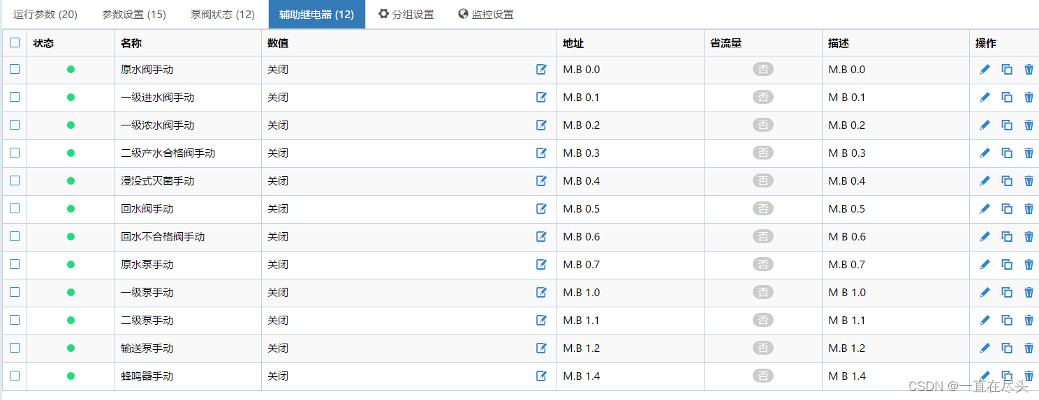
Step 7 Add remote manual point of equipment
That is, the auxiliary relay point, as shown in the figure:
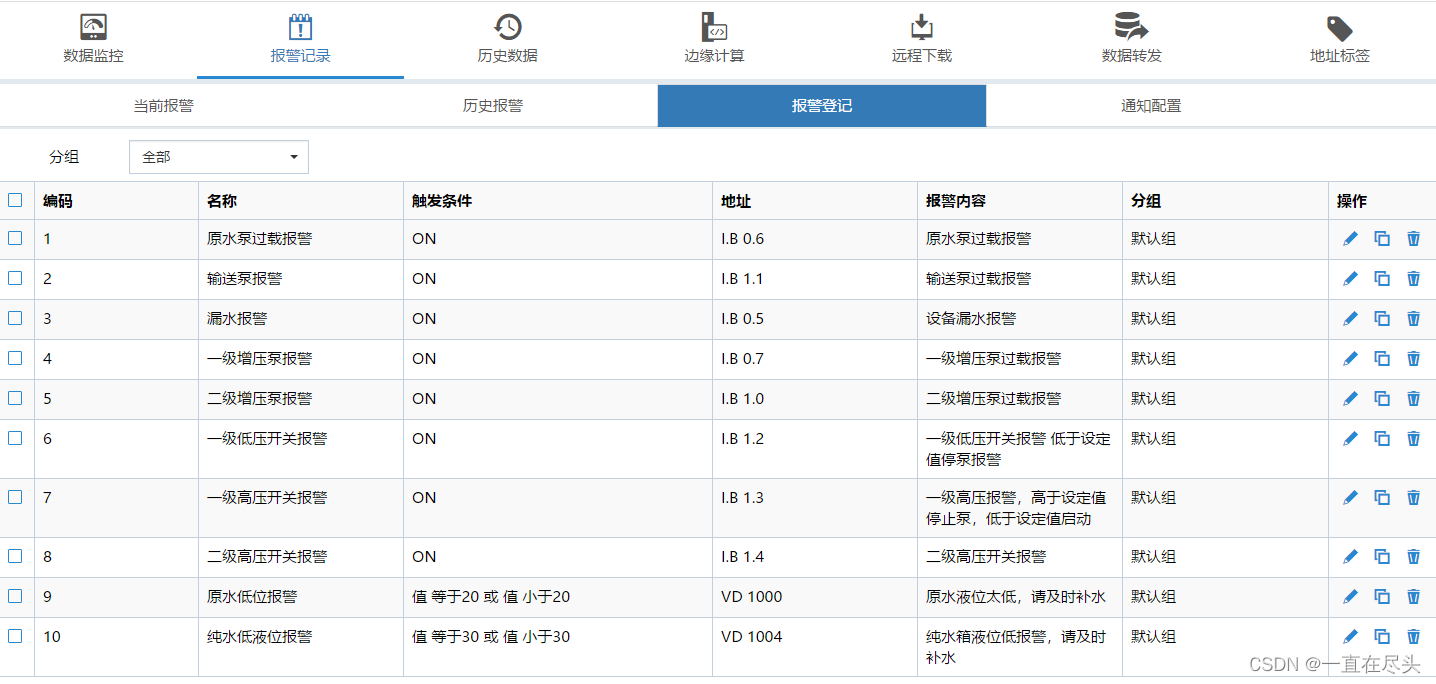
Step 8 Device alarm point registration
as the picture shows:
Step 9 Register historical data points of equipment
as the picture shows: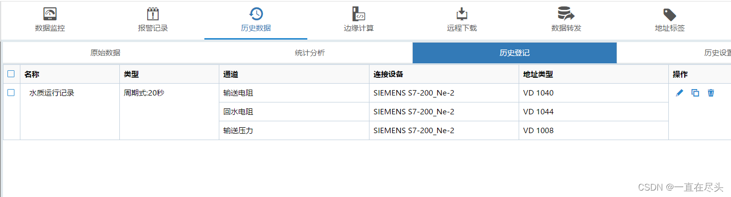
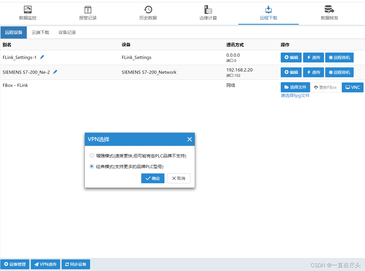
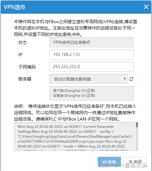
Step 10 Device remote operation and maintenance VPN connection
As shown in the figure:
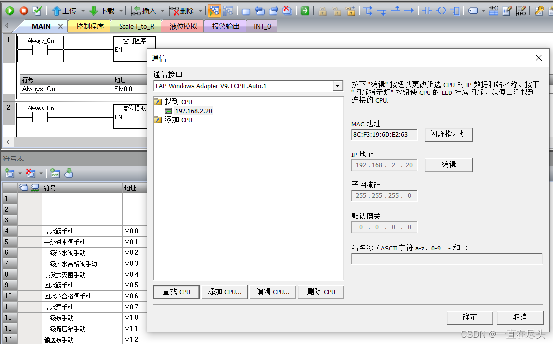
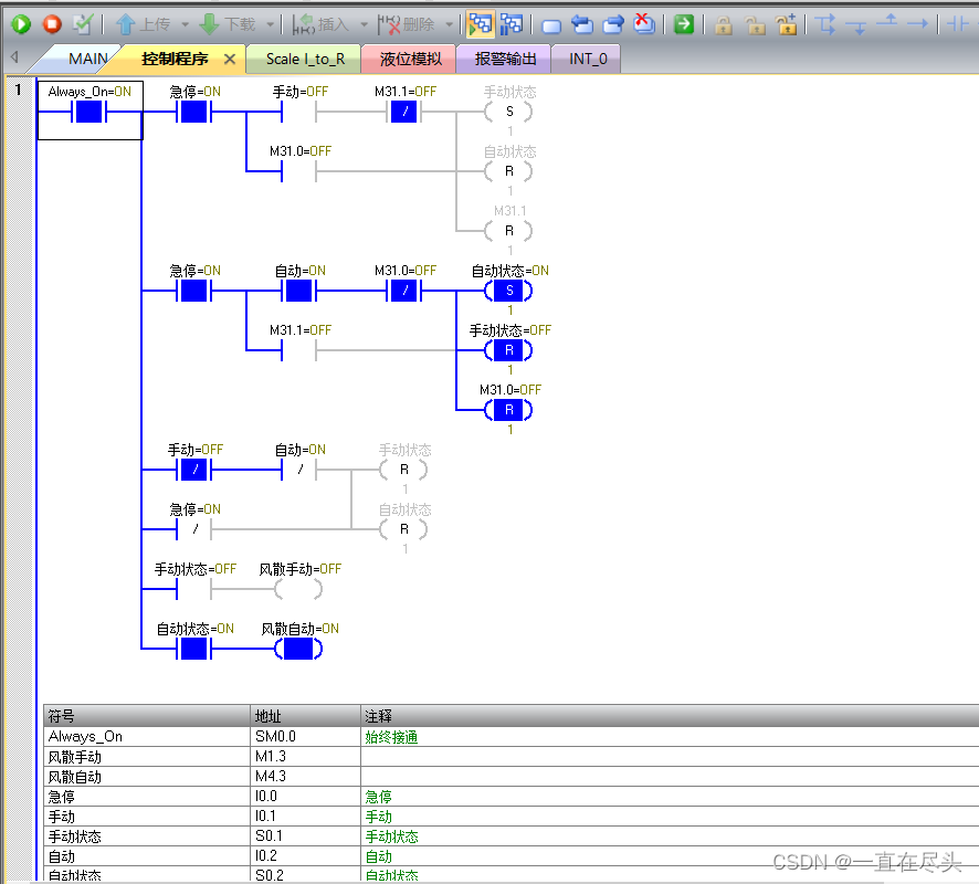
s7-200 smart PLC programming software operation

Step 11 Device touch screen cloud modification
The operation on the FStudio touch screen programming software is shown in the figure:
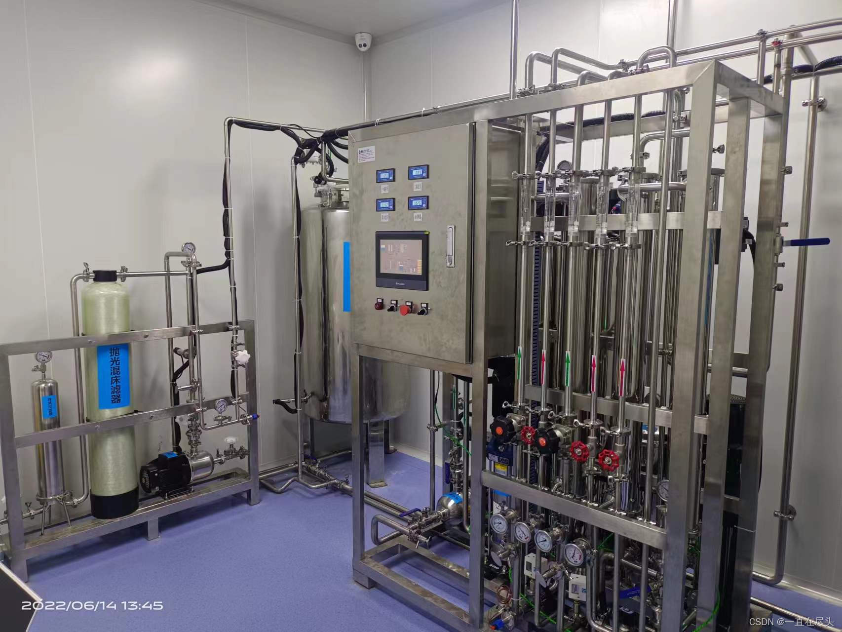
Step 12 On-site and cloud APP effects
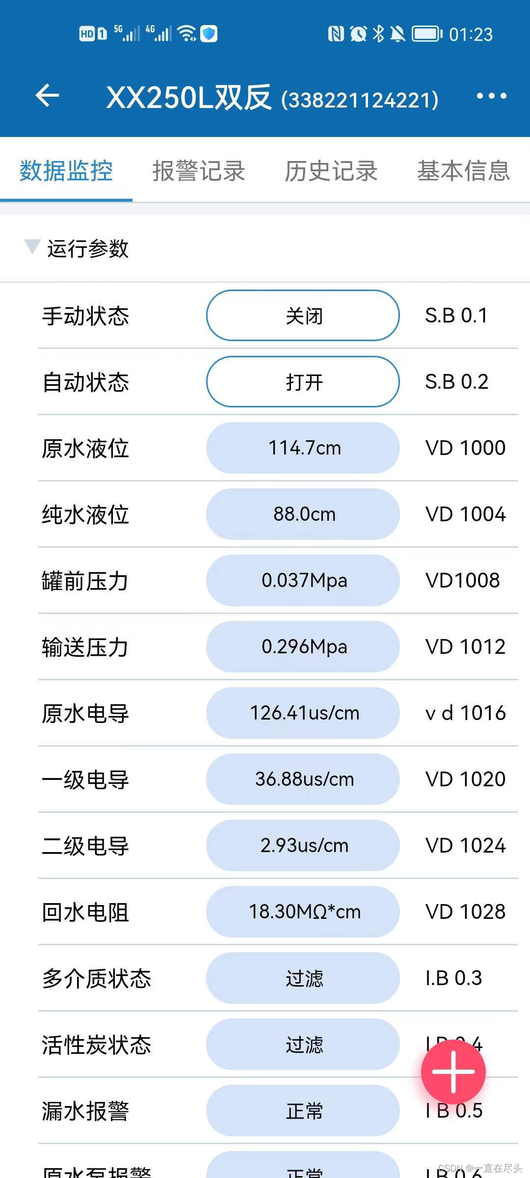
Summarize
The above is what we are going to talk about today. This article only briefly introduces the combined use of Flink-4G remote module and FlexManager, and FlexManager provides a lot of technologies that enable us to perform more specific IO operations and cloud computing on devices in the cloud. Slots, students can learn more about the application of FlexManager.