Huawei integrated network topology experiments, in conjunction with link aggregation router Huawei overview, the basic configuration of the switch device and Huawei
**什么是链路聚合?**
链路聚合是将多条物理链路捆绑为一条逻辑链路;
增强传输数据带宽和吞吐量;
链路聚合成员故障自动切换其他链路转发数据;
链路聚合将流量分散到不同成员链路进行转发数据,降低拥塞;
**链路聚合的作用是什么?**
加快传输速度,提供网络负载均衡;
华为设备的链路聚合相当于思科网络设备的以太网通道;
**链路聚合的模式**
1)手工模式
简称手工负载分担模式;
手动模式所有的链路聚合所有端口都参与转发数据和分担流量;
参与链路状态聚合的端口管理员手动添加;
手动模式链路状态聚合不会发送LACP链路状态聚合协议,只能手工负载分担;
支持居于源目标MAC和IP地址的负载均衡;
2)静态LACP模式
运行链路状态聚合的设备都会发送LACP协议进行协商链路聚合参数;
运行LACP协商选举活动端口和非活动端口;
静态LACP模式也被称为M:N模式;
M表示活动成员链路,N表示非活动链路冗余备份流量;
活动成员链路故障自动切换到优先级高的非活动链路转发数据;
3)手工模式和静态LACP模式的区别
手工负载模式中所有端口都属于转发状态;
静态LACP模式一部分端口为转发状态,一部分为备份状态;
**负载均衡的模式**
dst-ip(目的IP地址)模式:根据目标IP地址进行负载负担;
dst-mac(目的MAC地址)模式:根据目标MAC地址进行负载分担;
src-ip(源IP地址)模式:根据源IP地址进行负载分担;
src-mac(源MAC地址)模式:根据源MAC地址进行负载分担;
src-dst-ip(源IP地址与目的IP地址的异或)模式:根据源目标IP地址进行负载分担;
src-dst-mac(源MAC地址与目的MAC地址的异或)模式:根据源目标MAC地址进行负载
分担;
Type of link aggregation member Notes
- Each Eth-Trunk Interface can contain up to eight members of the interface;
- Member interfaces and functions can not be configured separately static MAC address;
- When adding an interface Eth-Trunk, to be the default hybrid interface (the default type is a Huawei device interface type);
- Eth-Trunk interface can not be nested, i.e., is not a member Eth-Trunk interfaces;
- An Ethernet interface to only one Eth-Trunk interface. To add other Eth-Trunk interface, you must first withdraw from the original Eth-Trunk interface;
- Eth-Trunk interface in a member interface must be the same type, i.e., the FE interface and a GE interface can not be added to the same Eth-Trunk interface;
- Ethernet interface boards may be of different interfaces to the same Eth-Trunk;
- If the local device using Eth-Trunk, with members of the peer directly connected to the interface must be bundled into an interface Eth-Trunk interface, such ends can not communicate;
- When the rates of members of an interface, congestion may occur in actual use a small rate interface and packet loss;
- After an interface is added Eth-Trunk, MAC address learning is to learn the Eth-Trunk, not in accordance with the member interfaces;
Huawei network topology is as follows apparatus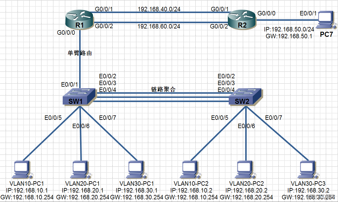
configuration steps: - PC, according to the topology configuration IP address and gateway
- SW1 and SW2 configuration aggregation and trunk
- Creating vlan10, vlan20, vlan30 respectively in SW1 and SW2, to add the interface vlan
- Route R1-arm configuration, communication between different vlan
- R1 is G0 / 0/1 Interface IP address and IP address of the interface configuration R2
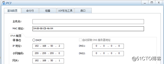
- PC7 configure the IP address and gateway
- R2 configure a default route, R1 configure a static route, PC7 can access all vlan, the whole network interworking
- R1 and R2 are arranged floating route
- PC7 route the whole network interworking floating verification
start configuration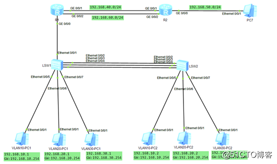
1.PC topology configuration unit according to the IP address and gateway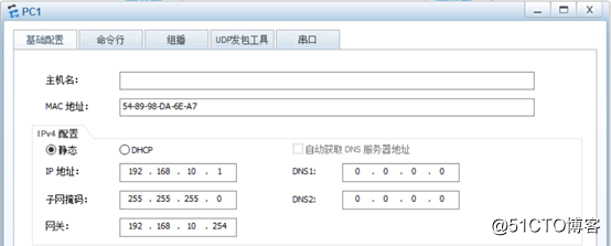
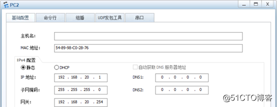
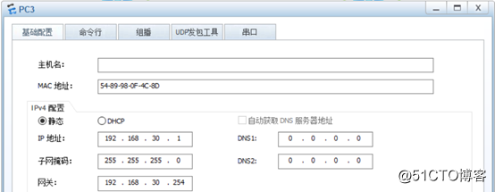
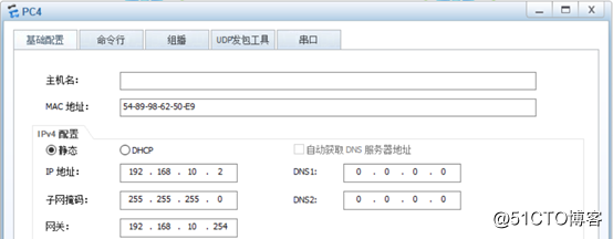

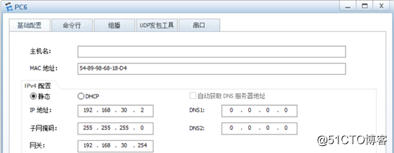
2.SW1和SW2配置链路聚合和trunk
1)SW1配置0/0/2、0/0/3、0/0/4接口为链路聚合
[SW1]int Eth-Trunk 1        #创建聚合链路编号为1,范围是0~63
[SW1-Eth-Trunk1]quit      #保存并退出
[SW1]int eth 0/0/2            #进入到0/0/2接口
[SW1-Ethernet0/0/2]eth-trunk 1       #加入到聚合链路1中
[SW1-Ethernet0/0/2]quit               #保存并退出
[SW1]interface Ethernet 0/0/3       #进入到0/0/3接口
[SW1-Ethernet0/0/3]eth-trunk 1     #加入到聚合链路1中
[SW1-Ethernet0/0/3]quit                #保存并退出
[SW1]interface Ethernet 0/0/4        #进入到0/0/4接口
[SW1-Ethernet0/0/4]eth-trunk 1      #加入到聚合链路1中
[SW1-Ethernet0/0/4]quit                  #保存并退出
2)将SW1链路聚合配置为trunk
[SW1]int Eth-Trunk 1                     #进入聚合链路1
[SW1-Eth-Trunk1]port link-type trunk           #聚合链路配置为trunk
[SW1-Eth-Trunk1]port trunk allow-pass vlan all  #设置承载所有vlan
(如果承载指定vlan的话把all换成vlan编号即可)
[SW1-Eth-Trunk1]quit          #保存并退出
3)将SW1连接路由器R1的Ethernet0/0/1接口配置为trunk
[SW1]int eth 0/0/1              #进入0/0/1接口
[SW1-Ethernet0/0/1]port link-type trunk      #接口配置为trunk
[SW1-Ethernet0/0/1]port trunk allow-pass vlan all    #设置承载所有vlan
[SW1-Ethernet0/0/1]quit                     #保存并退出
4)SW2配置0/0/2、0/0/3、0/0/4接口为链路聚合
[SW2]int Eth-Trunk 1 #创建聚合链路编号为1,范围0~63
[SW2-Eth-Trunk1]quit #保存并退出
[SW2]int eth 0/0/2 #进入到0/0/2接口
[SW2-Ethernet0/0/2]eth-trunk 1 #加入到聚合链路1中
[SW2-Ethernet0/0/2]quit #保存并退出
[SW2]int eth 0/0/3 #进入到0/0/3接口
[SW2-Ethernet0/0/3]eth-trunk 1 #加入到聚合链路1中
[SW2-Ethernet0/0/3]quit #保存并退出
[SW2]int eth 0/0/4 #进入到0/0/4接口
[SW2-Ethernet0/0/4]eth-trunk 1 #加入到聚合链路1中
[SW2-Ethernet0/0/4]quit #保存并退出
5)将SW2链路聚合配置为trunk
[SW2]int Eth-Trunk 1 #进入聚合链路1
[SW2-Eth-Trunk1]port link-type trunk #聚合链路配置为trunk
[SW2-Eth-Trunk1]port trunk allow-pass vlan all #设置承载所有vlan3.在SW1和SW2分别创建vlan10、vlan20、vlan30,将接口加入vlan
1)在SW1创建vlan10 vlan20 vlan30,将接口加入vlan
[SW1]vlan batch 10 20 30 #批量创建多个vlan
2)在SW1将接口加入vlan
[SW1]int eth 0/0/5 #进入0/0/5接口
[SW1-Ethernet0/0/5]port link-type access #设置为接入链路
[SW1-Ethernet0/0/5]port default vlan 10 #加入到vlan10
[SW1-Ethernet0/0/5]quit #保存并退出
[SW1]int eth 0/0/6 #进入到0/0/6接口
[SW1-Ethernet0/0/6]port link-type access #设置为接入链路
[SW1-Ethernet0/0/6]port default vlan 20 #加入到vlan20
[SW1-Ethernet0/0/6]quit #保存并退出
[SW1]int eth 0/0/7 #进入到0/0/7接口
[SW1-Ethernet0/0/7]port link-type access #设置为接入链路
[SW1-Ethernet0/0/7]port default vlan 30 #加入到vlan30
[SW1-Ethernet0/0/7]quit #保存并退出3)SW2创建vlan10 vlan20 vlan30,将接口加入vlan
[SW2]vlan batch 10 20 30 #批量创建多个vlan
4)在SW2将接口加入vlan
SW2]int eth 0/0/5 #进入0/0/5接口
[SW2-Ethernet0/0/5]port link-type access #设置为接入链路
[SW2-Ethernet0/0/5]port default vlan 10 #加入到vlan10
[SW2-Ethernet0/0/5]quit #保存并退出
[SW2]int eth 0/0/6 #进入到0/0/6接口
[SW2-Ethernet0/0/6]port link-type access #设置为接入链路
[SW2-Ethernet0/0/6]port default vlan 20 #加入到vlan20
[SW2-Ethernet0/0/6]quit #保存并退出
[SW2]int eth 0/0/7 #进入到0/0/7接口
[SW2-Ethernet0/0/7]port link-type access #设置为接入链路
[SW2-Ethernet0/0/7]port default vlan 30 #加入到vlan30
[SW2-Ethernet0/0/7]quit #保存并退出4.R1配置单臂路由,不同vlan间通信
1)R1开启子接口
[R1]int g 0/0/0.10 #创建子接口0/0/0.10
[R1-GigabitEthernet0/0/0.10]ip add 192.168.10.254 24 #子接口配置IP地址
[R1-GigabitEthernet0/0/0.10]dot1q termination vid 10 #子接口为vlan10服务
[R1-GigabitEthernet0/0/0.10]arp broadcast enable #开启子接口ARP广播
[R1-GigabitEthernet0/0/0.10]quit #保存并退出
[R1]int g 0/0/0.20 #创建子接口0/0/0.20
[R1-GigabitEthernet0/0/0.20]ip add 192.168.20.254 24 #子接口配置IP地址
[R1-GigabitEthernet0/0/0.20]dot1q termination vid 20 #子接口为vlan20服务
[R1-GigabitEthernet0/0/0.20]arp broadcast enable #开启子接口ARP广播
[R1-GigabitEthernet0/0/0.20]quit #保存并退出
[R1]int g 0/0/0.30 #创建子接口0/0/0.30
[R1-GigabitEthernet0/0/0.30]ip add 192.168.30.254 24 #子接口配置IP地址
[R1-GigabitEthernet0/0/0.30]dot1q termination vid 30 #子接口为vlan30服务
[R1-GigabitEthernet0/0/0.30]arp broadcast enable #子接口开启ARP广播
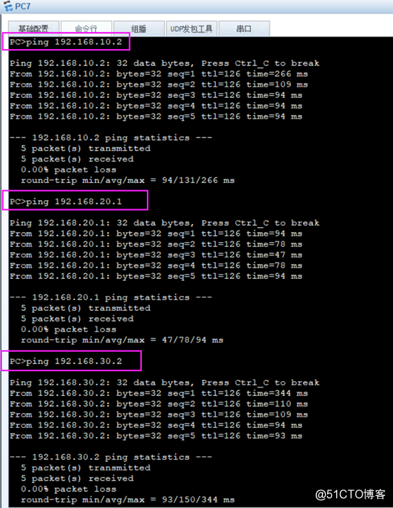
[R1-GigabitEthernet0/0/0.30]quit #保存并退出After the above configuration different vlan can communicate with each other, take a PC ping other vlan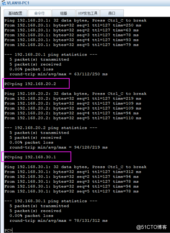
接下来配置静态、默认、浮动路由,全网互通
5.R1的G0/0/1接口配置IP地址和R2接口配置IP地址
1)R1的G0/0/1接口配置IP地址
[R1]int g 0/0/1        #进入0/0/1接口
[R1-GigabitEthernet0/0/1]ip add 192.168.40.1 24    #配置IP地址
[R1-GigabitEthernet0/0/1]undo shut      #激活接口
[R1-GigabitEthernet0/0/1]quit       #保存并退出
2)R2接口配置IP地址
[R2]int g 0/0/1     #进入0/0/1接口
[R2-GigabitEthernet0/0/1]ip add 192.168.40.2 24   #配置IP地址
[R2-GigabitEthernet0/0/1]undo shut       #激活接口
[R2-GigabitEthernet0/0/1]quit       #保存并退出
[R2]int g 0/0/0     #进入0/0/0接口
[R2-GigabitEthernet0/0/0]ip add 192.168.50.1 24    #配置IP地址
[R2-GigabitEthernet0/0/0]undo shut     #激活接口
[R2-GigabitEthernet0/0/0]quit             #保存并退出
6.PC7 configure the IP address and gateway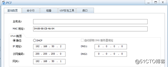
7.R2配置默认路由,R1配置静态路由,PC7可以访问所有vlan,全网互通
1)R2配置默认路由,下一跳地址为192.168.40.1
[R2]ip route-static 0.0.0.0 0.0.0.0 GigabitEthernet 0/0/1 192.168.40.1
                                            #配置默认路由,下一跳接口为0/0/1,下一跳IP地址为40.1
2)R1配置静态路由,下一跳为192.168.40.2
[R1]ip route-static 192.168.50.0 255.255.255.0 GigabitEthernet 0/0/1 192.168.40.2
                                            #配置静态路由,下一跳接口为0/0/1,下一跳IP地址为40.2
3) PC7 verify the whole network interoperability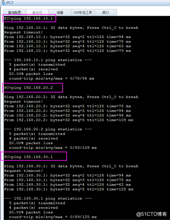
8.R1和R2配置浮动路由
1)配置R1和R2的G0/0/2接口的IP地址
[R1]int g 0/0/2      #进入0/0/2接口
[R1-GigabitEthernet0/0/2]ip add 192.168.60.1 24     #配置IP地址
[R1-GigabitEthernet0/0/2]undo shut                   #激活接口
[R1-GigabitEthernet0/0/2]quit              #保存并退出
[R2]int g 0/0/2         #进入0/0/2接口
[R2-GigabitEthernet0/0/2]ip add 192.168.60.2 24   #配置IP地址
[R2-GigabitEthernet0/0/2]undo shut      #激活接口
[R2-GigabitEthernet0/0/2]quit    #保存并退出
[R2]ip route-static 0.0.0.0 0.0.0.0 GigabitEthernet 0/0/2 192.168.60.1 preference 70
               #配置默认浮动路由,下一跳接口为G0/0/2  下一跳IP地址为60.1   优先级为70
[R1]ip route-static 192.168.50.0 24 GigabitEthernet 0/0/2 192.168.60.2 preference 70
                    #配置静态浮动   下一跳接口为G0/0/2    下一跳IP地址为60.2   优先级为70
2)关闭R1和R2的G0/0/1接口
[R1]int g 0/0/1      #进入0/0/1接口
[R1-GigabitEthernet0/0/1]shut   关闭接口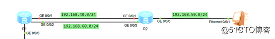
9.PC7 whole network routing verification floating exchange