Table of contents
Assignment 1: OSI/RM, TCP/IP addressing and underlying network technologies
Assignment 2: IP address planning and routing
Assignment 4: UDP, Routing Protocol
Assignment 1: OSI/RM, TCP/IP addressing and underlying network technologies
Which layer of OSI/RM does the physical address belong to? Does it need to be globally unique? In what scope should it be unique? Why is the physical address of the Ethernet network card—the MAC address required to be globally unique?
Answer: 1. Data link layer;
2. There is no need for global unification;
3. It should be unique in the same network segment (or LAN). The MAC (Media Access Control) address is the identifier for identifying the LAN (Local Area Network) node;
4. The MAC address is the physical address of the network card. The MAC address is assigned by the manufacturer. Network cards generated by multiple manufacturers may be used in the same LAN. In order to distinguish the network cards, it is necessary to ensure that the MAC address is globally unique.
When configuring Internet Protocol (TCP/IP) properties on a PC using a Windows system, does the "default gateway" refer to the router (Router) or the gateway (Gateway)? What's the reason?
Answer: Router;
"Default gateway" means that if a host cannot find an available gateway, it will send the data packet to the default designated gateway, and this gateway will process the data packet. From a functional point of view, it mainly performs the function of routing and forwarding of data packets, so when configuring protocol properties on Windows, the default gateway refers to the router.
The gateway mainly performs the protocol conversion function.
3. Complete the following struct statement and use it to describe the Ethernet frame format (RFC 894, starting with "destination address").
struct Ethernet_frame
{
……
unsigned long intCRC;
};
struct Ethernet_frame
{
unsigned long int DMAC ;
unsigned long int SMAC ;
unsigned long int Type ;
char *data;
unsigned long int CRC;
};
4. What fields should the Ethernet frames received from the physical layer by the Ethernet link layer (MAC sublayer) include? Why? What fields should the Ethernet frame received by the interface driver software of the Ethernet network card include? Why?
What fields should the Ethernet frames received from the physical layer by the Ethernet link layer (MAC sublayer) include?
Answer: Preamble, frame start delimiter; destination MAC address, source MAC address, type field (type of upper layer protocol, Type/len< a i=2>), data field, check field;
Cause: The Ethernet frame received by the MAC layer from the physical layer carries physical layer information, including the preamble and frame start delimiter< a i=2>, the link layer of Ethernet does not process this information.
What fields should the Ethernet frame received by the interface driver software of the Ethernet network card include?
Destination MAC address, source MAC address, type field (type of upper layer protocol), data field, check field;
Reason: The Ethernet frame received by the interface driver software of the Ethernet network card has been processed by the network card, and the physical layer information such as preamble and frame start delimiter has been processed.
But when using wireshark to analyze the frame from the network card, it does not contain the check field.
Please visit the IETF homepage (http://www.ietf.org), find 1 to 2 active working groups that you are interested in, and write down the full name, abbreviation and field of the working group (in English), briefly Describe the main research content of the working group (in Chinese), and give the number, name and status of the latest RFC issued by the working group.
answer:
全称:Inter-Domain Routing
Abbreviation: idr
Area:Routing Area (rtg)
Main research content: Mainly responsible for BGP research; the IDR working group will work on the accuracy, robustness and scalability of the protocol, as well as the clarity and accuracy of the protocol Border Gateway Protocol Documentation Set.
RFC number: RFC9294
RFC名称:draft-ietf-idr-bgp-ls-app-specific-attr
RFC状态:Proposed Standard RFC
全称:Light-Weight Implementation Guidance (lwig)
Short copy:lwig
Area:Internet Area
Main research content: Build minimal but interoperable IP devices that can work in most environments; collect experience from the use of IP stacks.
RFC number: RFC 9178
RFC名称:draft-ietf-lwig-cellular
RFC状态:Informational RFC
Assignment 2: IP address planning and routing
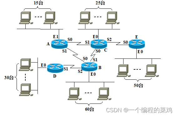
Plan the IP address according to the network topology shown in the figure below.
Require:
- If the total IP address space is 10.1.1.0/24, can each IP network be allocated the appropriate IP address space based on the network sizes shown in the diagram? If so, how should it be addressed? If not, please explain why. \\

No; the address space is not enough;
Explanation: The required number of addresses for each IP network = the number of hosts in this subnet + the number of router interfaces in this subnet + 2
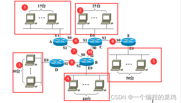
As can be seen from the above network topology diagram, there are a total of 10 subnets.
Analyze subnets with hosts:
Subnet 1: Number of addresses = 15+1+2=17, 32 addresses required
Subnet 2: Number of addresses = 25+1+2=18, 32 addresses required
Subnet 3: Number of addresses = 30+1+2=33, 64 addresses required
Subnet 4: Number of addresses = 50+1+2=53, 64 addresses required
Subnet 5: Number of addresses = 60+1+2=63, 64 addresses required
Subnet 6: Number of addresses = 2+2=4, 4 addresses are required
Subnet 7: Number of addresses = 2+2=4, 4 addresses are required
Subnet 8: Number of addresses = 2+2=4, 4 addresses are required
Subnet 9: Number of addresses = 2+2=4, 4 addresses are required
Subnet 10: Number of addresses = 2+2=4, 4 addresses are required
Now the number of addresses in the address block is 28 =256, and (32+32+64+64+64+4*5 )>256, the number of addresses is not enough
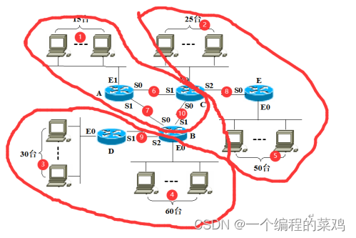
- The total IP address space is 10.1.0.0/16, please adopt aggregation design as shown in the figureNetwork sizeAssign appropriate IP address space to each IP network so thatthe minimum number of routing table entries per router a>. Write the network address, mask and direct broadcast address of each IP network, and write the IP address of each network interface of each router, as well as the IP address and subnet mask of a host in each subnet with a host. code and default gateway.
Use routing address aggregation:
Distributive IP location10.1.0.0/16, the required land size is 32+32+64+64+64+4*5=276,
So just assign the 10.1.0.0/23 address block to the entire network.
Adopt a converged design
3, 4, and 9 can be aggregated into a network, requiring the address 64+64+4 A total of 256 addresses
1 A single network requires 32 addresses
Network 1 , 6, 7 , 10 are aggregated into one network, requiring 64 addresses
2 , 8 , 5 are aggregated into a network, which requires 32+4+64, a total of 128 addresses
The schematic diagram of address aggregation is as follows:
 |
The route aggregation table is as follows. Each bar represents an address block of 128 sizes.
| Network 3 10.1.0.0/26 |
Network 4 10.1.0.64/26 |
10.1.0.0/24 |
|||||||
| Network 9 10.1.0.128/30 |
|||||||||
| Network 5 10.1.1.0/26 |
网络2 10.1.1.64 /27 |
网络8 10.1.1.96/30 |
10.1.1.0/25 |
||||||
| Network 6 10.1.1.128/30 |
Network 7 10.1.1.132/30 |
Network 10 10.1.1.136/30 |
Network 1 10.1.1.160/27 |
10.1.1.128/25 |
|||||
| network name |
website address |
subnet mask |
broadcast address |
| Subnet 1 |
10.1.1.160 |
255.255.255.224 |
10.1.1.191 |
| Subnet 2 |
10.1.1.64 |
255.255.255.224 |
10.1.1.95 |
| Subnet 3 |
10.1.0.0 |
255.255.255.192 |
10.1.0.63 |
| Subnet 4 |
10.1.0.64 |
255.255.255.192 |
10.1.0.127 |
| Subnet 5 |
10.1.1.0 |
255.255.255.192 |
10.1.1.63 |
| Subnet 6 |
10.1.1.128 |
255.255.255.252 |
10.1.1.131 |
| Subnet 7 |
10.1.1.132 |
255.255.255.252 |
10.1.1.135 |
| Subnet 8 |
10.1.1.96 |
255.255.255.252 |
10.1.1.99 |
| Subnet 9 |
10.1.0.128 |
255.255.255.252 |
10.1.0.131 |
| Subnet 10 |
10.1.1.136 |
255.255.255.252 |
10.1.1.139 |
| router |
interface |
IP address |
| A |
E1 |
10.1.1.161 |
| S1 |
10.1.1.133 |
|
| S0 |
10.1.1.129 |
|
| B |
S0 |
10.1.1.134 |
| S1 |
10.1.1.137 |
|
| S2 |
10.1.0.129 |
|
| E0 |
10.1.0.65 |
|
| C |
S0 |
10.1.1.138 |
| S1 |
10.1.1.130 |
|
| S2 |
10.1.1.97 |
|
| E0 |
10.1.1.65 |
|
| D |
S1 |
10.1.0.130 |
| E0 |
10.1.0.1 |
|
| AND |
S0 |
10.1.1.98 |
| E0 |
10.1.1.1 |
The IP address, subnet mask, and default gateway of a host in each subnet with hosts.
| network name |
Host IP |
subnet mask |
Default gateway |
| Subnet 1 |
10.1.1.162 |
255.255.255.224 |
10.1.1.161 |
| Subnet 2 |
10.1.1.66 |
255.255.255.224 |
10.1.1.65 |
| Subnet 3 |
10.1.0.2 |
255.255.255.192 |
10.1.0.1 |
| Subnet 4 |
10.1.0.66 |
255.255.255.192 |
10.1.0.65 |
| Subnet 5 |
10.1.1.2 |
255.255.255.192 |
10.1.1.1 |
(3) Based on the IP address allocation plan in (2), please write the routing tables of routers A, B, C, D and E in the following format.
| destination network address |
destination mask |
Next hop IP address |
Send interface |
Router A’s routing table:
| destination network address |
destination mask |
Next hop IP address |
Send interface |
| 10.1.1.160 |
255.255.255.224 |
_ |
E1 |
| 10.1.0.0 |
255.255.255.0 |
10.1.1.134 |
S1 |
| 10.1.1.0 |
255.255.255.128 |
10.1.1.130 |
S0 |
Router B’s routing table:
| destination network address |
destination mask |
Next hop IP address |
Send interface |
| 10.1.0.64 |
255.255.255.192 |
_ |
E0 |
| 10.1.1.160 |
255.255.255.224 |
10.1.1.133 |
S0 |
| 10.1.1.0 |
255.255.255.128 |
10.1.1.138 |
S1 |
| 10.1.0.0 |
255.255.255.192 |
10.1.0.130 |
S2 |
Router C’s routing table:
| destination network address |
destination mask |
Next hop IP address |
Send interface |
| 10.1.1.64 |
255.255.255.224 |
_ |
E0 |
| 10.1.0.0 |
255.255.255.0 |
10.1.1.137 |
S0 |
| 10.1.1.128 |
255.255.255.224 |
10.1.1.129 |
S1 |
| 10.1.1.0 |
255.255.255.192 |
10.1.1.1 |
S2 |
Router D’s routing table:
| destination network address |
destination mask |
Next hop IP address |
Send interface |
| 10.1.0.0 |
255.255.255.192 |
_ |
E0 |
| 0.0.0.0 |
0.0.0.0 |
10.1.0.129 |
S1 |
Router E’s routing table:
| destination network address |
destination mask |
Next hop IP address |
Send interface |
| 10.1.1.0 |
255.255.255.192 |
_ |
E0 |
| 0.0.0.0 |
0.0.0.0 |
10.1.1.97 |
S0 |
Assignment 3: ARP, IP, ICMP
- The IP address of a network interface of Router A is 195.23.67.3, the mask is 255.255.255.0, and the Ethernet physical address is 0x2345AB4F67CD. The router receives an IP packet with the destination IP address 185.11.78.10. When the router checks the routing table, it finds out that the packet should be delivered to the next hop Router B, whose IP address is 195.23.67.9 and whose mask is 255.255.255.0 , please write down the contents of the ARP request packet sent by Router A and the ARP response packet received, as well as the header fields of the data frame encapsulating these two packets. Assume: The MAC address corresponding to 195.23.67.9 is 0x154983AF6CD2, and the MAC address corresponding to 185.11.78.10 is 0x94EF65A3B2D7.
ARP request packet sent by Router A:
| 0x0001 |
0x0800 |
|
| 0x06 |
0x04 |
0x0001 |
| 0x2345AB4F67CD |
||
| 195.23.67.3 |
||
| 0x000000000000 |
||
| 195.23.67.9 |
||
Data frameHeader field:
| preamble |
frame start delimiter |
0xFFFFFFFFFFFF |
0x2345AB4F67CD |
0x0806 |
ARP grouping and padding fields |
FCS |
ARP response packet received by Router A:
| 0x0001 |
0x0800 |
|
| 0x06 |
0x04 |
0x0002 |
| 0x154983AF6CD2 |
||
| 195.23.67.9 |
||
| 0x2345AB4F67CD |
||
| 195.23.67.3 |
||
Data frameHeader field
| preamble |
frame start delimiter |
0x2345AB4F67CD |
0x154983AF6CD2 |
0x0806 |
ARP grouping and padding fields |
FCS |
Analyze the "Packet Reception" section of RFC826 about the reception and processing of ARP packets, and point out the incorrect or inaccurate description of the reception and processing of ARP packets in "Table 8.3 Input Module" in Section 8.4.4 of the textbook.
answer:
- First, did not check whether the hardware address type of the received packet is supported
- Secondly, the type of the protocol address is not checked, nor is the length of the protocol address
- Furthermore, PENDING is not mentioned in the standard, nor is there any subsequent operation. RFC826 mentions the change of Merge_flag status.
- Finally, before judging that it is an ARP request, you should first judge whether it is the destination protocol address in the ARP packet. If not, it should be discarded.
When an IP datagram arrives, its header information is as follows:
45 00 00 54 00 03 00 00 20 06 00 00 7C 4E 03 02 B4 0E 0F 02
Try answering the following questions:
-
- Does this datagram have options fields?
- Is it fragmented?
- What is the length of the data portion of the datagram?
- Which high-level protocol data is encapsulated in the datagram?
- What is the TTL value?
answer:
- There is no option field. Because there are 20 bytes in total. Option fields will not be included
- 没有被分片,分片标志位和分片偏移量都为0
- 64字节。
- TCP
- 32(十进制)
试用一张表来归纳说明:哪些类型的ICMP差错报告报文是由路由器发送的?哪些类型的ICMP差错报告报文是由目的主机发送的?
| ICMP差错报文类型 |
路由器发送 |
目的主机发送 |
||
| Code |
内容 |
Code |
内容 |
|
| 终点不可达 |
0 |
网络不可达(可能硬件问题) |
2 |
协议不可达 |
| 1 |
主机不可达(可能是硬件问题) |
3 |
端口不可达 |
|
| 4 |
需要进行分片 |
|||
| 5 |
源路由不能完成 |
|||
| 6 |
目的网络未知 |
|||
| 7 |
目的主机未知 |
|||
| 8 |
源主机被隔离了 |
|||
| 9/10 |
从管理上禁止与目的网络通信 |
|||
| 11/12 |
对指明的服务类型,主机不可达 |
|||
| 13 |
主机不可达,因为管理员已经在主机上放置了过滤器 |
|||
| 14 |
主机不可达,因为主机违反了优先级策略 |
|||
| 15 |
主机不可达,因为它的优先级被截至 |
|||
| 源点抑制 |
路由器因为拥塞或者流量控制丢弃报文 |
目的主机因为拥塞或者流量控制丢弃报文 |
||
| 超时 |
报文的生存时间变为了0 |
目的主机没有在规定时间内收到所有的分片 |
||
| 参数问题 |
0 |
路由器发现首部某个字段有差错或者二义性 |
0 |
目的主机发现首部某个字段有差错或者二义性 |
| 1 |
路由器发现表示缺少所需的选项部分 |
1 |
目的主机发现表示缺少所需的选项部分 |
|
| 路由重定向 |
0 |
对特定网络路由发生改变 |
||
| 1 |
对特定主机路由发生改变 |
|||
| 2 |
基于指定服务类型的对特定网络路由发生改变 |
|||
| 3 |
基于指定服务类型的对特定主机路由发生改变 |
|||
作业4:UDP、Routing Protocol
- 路由器A的路由表如下:
| 目的网络 |
Metric |
Next-hop |
| Net1 |
1 |
B |
| Net2 |
4 |
C |
| Net3 |
1 |
D |
| Net4 |
5 |
E |
| Net5 |
3 |
B |
若该路由器收到来自路由器B的RIP报文如下:
| 目的网络 |
Metric |
| Net1 |
1 |
| Net2 |
2 |
| Net3 |
3 |
| Net4 |
7 |
| Net5 |
3 |
请按照RFC1058中定义的RIP更新算法,写出路由器A更新后的路由表。
答:
| 目的网络 |
Metric |
Next-hop |
| Net1 |
2 |
B |
| Net2 |
3 |
B |
| Net3 |
1 |
D |
| Net4 |
5 |
E |
| Net5 |
4 |
B |
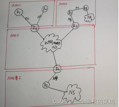
- 试画出具有以下规约的自治系统:
a、共有8个网络:N1~N8,有8台路由器:R1~R8
b、共有4个OSPF区域:Area 0 ~ Area 3
c、N3、N5、N8是以太网,其余均为点到点网络
d、R1连接N1
e、R2连接N2
f、R3连接N1、N2和N3
g、R4连接N3和N4
h、R5连接N4和N5
i、R6连接N3和N6
j、R7连接N6和N7
k、R8连接N7和N8
l、N1和N2在Area 1中,N4和N5在Area 2中,N6~N8在Area 3中
m、N3在Area 0中
试回答以下问题:
-
- 该自治系统中的路由器分别是哪种类型的OSPF路由器?
- 该自治系统中会产生哪几种类型的OSPF LSA?
- 该自治系统中哪几台路由器的链路状态数据库完全一致?
- 该自治系统中有哪几种类型的OSPF链路?
答:
自治系统的拓扑如下:
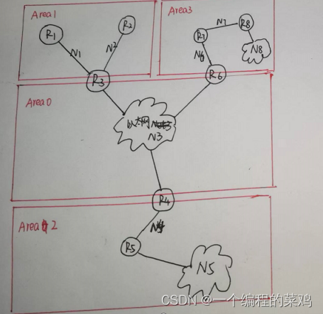
a) 内部路由器:R1,R2,R5,R7,R8
主干路由器:R3、R6、R4
区域边界路由器:R3、R6、 R4,
AS边界路由器:无
b)Type1:Router-LSA(路由器链路通告)
Type2:Network-LSA(网络链路通告)
Type3:Summary-LSA(汇总链路到网络)
c) R1和R2;
R7和R8;
R3 、R4和R6
d) 点到点链路(point-to-point)
转接链路(transient)
残桩链路(stub)
IP协议和UDP协议都是一种不可靠的无连接数据报交付协议,使用无连接、不可靠传输服务的应用进程为什么不能直接使用IP协议进行传输?
原因1:IP只能实现端到端的传输,传输层需要进程到进程,需要端口来识别,不同的应用进程需要不同的端口号(port)标识,而IP协议不提供端口号的标识,所以在此基础之上是无法替代的。
原因2:传输层和网络层在操作系统内的实现层次不同,给用户开放的权限也不同,并非所有用户都可以直接操作IP协议,出于安全和易操作性的考虑,现代操作系统往往不允许/不建议普通用户直接操作IP协议,一般是用户完成传输层协议封装,然后由操作系统进行网络层封装和校验和计算。
原因3:IP是需要进行验证,UDP不需要进行验证,速度快,
原因4:IP协议比较复杂,需要考虑路由等,而UDP协议简单,应用进程直接用UDP协议,会更加的简单化,用户操作性强。
作业五
试画出具有以下规约的自治系统:
a、共有8个网络:N1~N8,有8台路由器:R1~R8
b、共有4个OSPF区域:Area 0 ~ Area 3
c、N3、N5、N8是以太网,其余均为点到点网络
d、R1连接N1
e、R2连接N2
f、R3连接N1、N2和N3
g、R4连接N3和N4
h、R5连接N4和N5
i、R6连接N3和N6
j、R7连接N6和N7
k、R8连接N7和N8
l、N1和N2在Area 1中,N4和N5在Area 2中,N6~N8在Area 3中
m、N3在Area 0中
试回答以下问题:
-
- 该自治系统中的路由器分别是哪种类型的OSPF路由器?
- 该自治系统中会产生哪几种类型的OSPF LSA?
- 该自治系统中哪几台路由器的链路状态数据库完全一致?
- 该自治系统中有哪几种类型的OSPF链路?
a) 内部路由器:R1,R2,R5,R7,R8
主干路由器:R3、R6、R4
区域边界路由器:R3、R6、 R4,
AS边界路由器:无
b)Type1:Router-LSA(路由器链路通告)
Type2:Network-LSA(网络链路通告)
Type3:Summary-LSA(汇总链路到网络)
c) R1和R2;
R7和R8;
R3 、R4和R6
d) 点到点链路(point-to-point)
转接链路(transient)
残桩链路(stub)
主机A的发送窗口大小为2000字节。第1秒钟,主机A向主机B发送了第1个报文段:序号为2001,发送了800字节数据,重传计时器为5秒。第2秒钟,主机A向主机B发送了第2个报文段:序号为2801,发送了800字节数据,重传计时器为5秒。第3秒钟,主机A收到来自主机B的1个TCP确认报文段:确认号为2801,窗口字段值为1600。此时,主机A的发送窗口将如何改变?如果主机A要在第4秒钟向主机B发送第3个TCP报文段,该报文段的序号是多少?该报文段中的数据长度是多少字节?
①主机A的发送窗口应该变为1600。发送方的窗口将会根据接收方的窗口进行调整,主机A收到了TCP确认报文段,窗口字段值为1600,所哟主机A的发送窗口应该变为1600。
②序号为3601,报文长度最大为800字节(报文数据长度小于等于800字节)。第四秒钟主机A向主机B发送第三个TCP报文段,由于之前发送了序号为2801,800字节的数据,此时的发送窗口为1600,而且还没有收到之前的确认报文段,所以还能发送序号为3601,报文长度最大为800字节。
- 试举例说明什么情况下TCP会从FIN-WAIT-1状态转换到TIME-WAIT状态?
①通信双方同时关闭连接。
②说明:在这种FIN-WAIT-1状态之下,一方发起关闭后,发送了FIN,等待对方ACK 的时候,正好被动方也发起关闭请求,发送了FIN。这时客户端接收到了先前ACK, 也收到了对方的FIN,然后发送ACK(对对方FIN的回应),然后就进入TIME-WAIT 状态。