1. Sensor
The sensors in autonomous driving mainly use lidar, millimeter-wave radar, camera, and ultrasonic. The advantages and disadvantages are as follows:
1) LiDAR has strong ranging accuracy, ranging range and adaptability to temperature and light. The disadvantage is that the wiring harness is low, the recognition is not good, and the target (especially non-metallic objects) may be missed.
2) The camera has a lot of environmental detail information, but the lighting has too much influence.
3) The biggest advantage of millimeter waves is that the detection angle is relatively large, the anti-interference is strong, and the performance is relatively stable. The disadvantage is that the resolution and accuracy are poor
4) The accuracy of ultrasonic radar is poor, and the detection distance is short, only 3m.
2. Calibration
Sensor calibration mainly includes internal reference and external reference. The internal parameters are mainly parameters such as focal length, aperture, and camera center offset, which can be obtained directly or determined by a simple algorithm. The main thing here is the calibration of external parameters. The external parameters describe the relative positional relationship between the sensor and other given coordinates. Therefore, the external parameters here are described as the external parameters between the telephoto camera and the short-focus camera. The external parameters between radars, or the external parameters between radars, need to be calibrated separately.
The way of calibration is to use the calibration room to calibrate, or to use the algorithm to calibrate. Use the calibration room for calibration, and set some reference objects, mostly objects with corners, for easy positioning. Error correction can also be performed after calibration. specific method:
(1) Camera calibration: multi-point image data VS corresponding corner data of multi-point reference objects Method: PNP algorithm
(2) Point cloud calibration: Multi-point point cloud coordinates VS multi-point reference object point cloud data Method: ICP algorithm
Different cameras use PNP to obtain a matrix, and pass the two matrices. Generally, the inverse of one matrix is multiplied by the other matrix to obtain the external parameters, and the same is true for point clouds.
3. Detection
Common algorithms for 2D image detection: SSD; yolo series; centernet
Common algorithms for 3D point cloud detection:
(1) Segmentation: birdview segmentation; (2) Detection: MV3D
Popular algorithms: VoxelNet, SECOND, PointPillars, Centerpoint
PointPillars
Each point of Pillars actually has xyz or other features, so the point itself is also a feature vector. Then through our fully connected layer, Bath Norm, ReLU, and Max Pooling, these conventional operations are converted into a global feature in Pillar, a feature vector representing Pillar. This process is actually a simplification of the process of converting VoxelNet into Voxel, and it is the process of learning Voxel encoding by VoxelNet. After VoxelNet obtains a global feature at the end, it also needs to concat the global feature back, that is to say, each person copies a copy and then returns to the original point, and then continues to iterate this process. In the final memory The inside is to use the last global feature as the entire feature vector of VoxelNet. So PFE is actually a simplification that speeds up the iterative process.

Loss function:
PointPillars originally used Focal loss as its classification loss function. Focal loss was proposed in 2018. It is also used for two-dimensional target detection to improve a problem of unbalanced categories and an unbalanced ratio of positive and negative samples. The formula has two parameters α and γ. These two parameters need to pre-set a hyperparameter, and the hyperparameter itself needs to be adjusted a priori. In the actual test, it is found that these parameters are not particularly easy to adjust, because some prior information needs to be used, so it is replaced with a weighted softmax loss, which has better generalization, because without those hyperparameters, the detection after generalization The effect has improved, and this weighting means that some analogies are given greater weight.
Pillar feature encoding:
The structure on the left is the original one, and the one on the right is improved. When the feature of the point is obtained, it originally includes the xyz coordinates of the point and the intensity of the reflectivity. Of course, there may be other features. First, make a radius Replacement is to make a preliminary transformation of the features inside. Then perform the following operations, Linear, Batch Norm, Relu, MaxPooling, to get the characteristics of the last global Pillar.
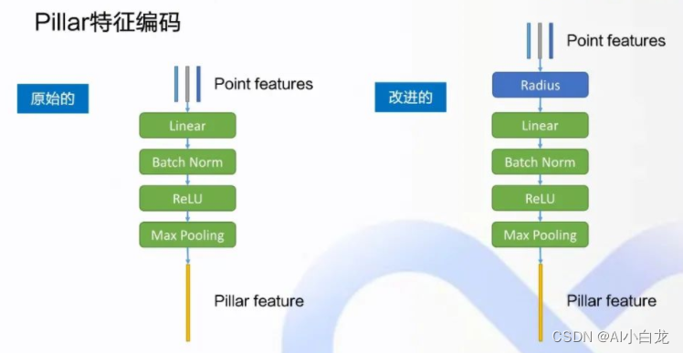
Next, replace the point features with Radius: In the point cloud image from the perspective of BEV on the right, the origin O of the coordinate system is actually the lidar sensor on the car, the positive direction of x is facing forward, and Y is on the left In the positive direction of the axis, first calculate a radius, which is the second norm of xy, that is to say, on the xy plane of the BEV perspective, the distance between this point and the origin is the radius, which is used to replace the original feature xy of the point, plus Y intensity , forming the features after point transformation. The point cloud of lidar is composed of circles of points, which are obtained by rotating the laser reflector almost continuously. In addition, in the target detection from the BEV perspective, the status of X and Y is actually equal, so replace xy with radius, and treat this radius as the basic feature of a point, which is more in line with the point cloud is a circle This original feature is helpful for the improvement of the network.
RPN network design:
RPN is an encoding and decoding network originally proposed in Fast-RCN for two-dimensional target detection. By setting the initial detection frame on the grid point in advance, and then corresponding to the feature map, after subsequent processing, we get The probability scores and target categories contained in these candidate boxes are further screened to obtain the final detection box. For those initial candidate frame proposals, at the beginning, it is necessary to take some initial anchors on the original image to provide the initial frame. In the two-dimensional target detection, that is, in the target detection for the image, because the same target, at different shooting angles, the size on the image is different, and there is some distance relationship, so it is necessary to set multi-anchor In the target detection of the image, you can use different sizes and different aspect ratios to cover these targets in the matching image as much as possible.
Multi-head's improvement to RPN: Apollo's PointPillars model supports 9 categories, 4 of which are relatively large categories (Large head), such as cars, trucks, buses, and engineering vehicles. For the other 5 small heads, pedestrians, bicycles, motorcycles, ice cream cones, etc., there is a gap in their size on the BEV map, and there is some gap in the perspective of these heads in the top view. Therefore, these categories must be separated and divided into two different RPN heads for detection. For example, before we get the final feature map, we use a convolutional layer to output the probability score of the class category of the target, as well as the regression value of the body box, and its direction.
4. Fusion Tracking
An object tracker tracks segmentally detected obstacles. Typically, it forms and updates tracklists by associating current detections with existing tracklists, deleting old tracklists if they no longer exist, and generating new tracklists when new detections are identified. The motion state of the updated track list will be estimated after association. In the HM object tracker, the Hungarian algorithm (Hungarian algorithm) is used to detect the tracking association, and the robust Kalman filter (Robust Kalman Filter) is used for motion estimation.
The tracking process can be divided into:
-
Preprocessing; (lidar->local ENU coordinate system transformation, tracking object creation, tracking target saving)
-
Kalman filter filtering , predicting the current position and velocity of the object; (Kalman filtering stage 1: Predict stage)
-
Hungarian algorithm matching , associating detection objects and tracking objects;
-
Kalman filter to update the position and velocity information of the tracked object. (Kalman filter stage 2: Update stage)
The bipartite graph matching of the Hungarian algorithm is performed on the Object detected at each moment and the TrackedObject in the tracking list , and the matching results are divided into three categories:
-
If the match is successful, use the Kalman filter to update information (center of gravity position, velocity, acceleration) and other information;
-
If there is a mismatch and the corresponding TrackedObject is missing, encapsulate the Object into a TrackedObject and add it to the tracking list;
-
For the TrackedObject whose target is missing at the current moment in the tracking list (the Object cannot match it), the speed at the previous moment is used, and information such as the center of gravity position and acceleration at the current moment is used (the Kalman filter cannot be used to update, and the observation state is missing). For those track objects that are lost for too long, remove them from the track queue.
In the stage of tracking object information fusion, the main work of Apollo is to give a sequence of tracked objects:
(Time_1,TrackedObject_1),
(Time_2,TrackedObject_2),
...,
(Time_n,TrackedObject_n)
Every time the callback of LidarSubNode is executed, the tracking list will be refreshed, and the information of a tracked object will also be refreshed (center of gravity position, velocity, acceleration, CNN object segmentation--probability of foreground, CNN object segmentation--probability of each category) . N calls will get N probability distributions (N CNN object segmentation - foreground probability score, N CNN object segmentation - various object probability Probs), we need to determine the category attribute of the object in each callback process, Of course the easiest way is definitely argmax(Probs). However, CNN segmentation may be noisy, so the best way is to combine the N results for judgment.
Reference: Developer Says|Apollo Perceptual Analysis Tracking Object Information Fusion