Table of contents
1: TIM output comparison function
6: Practical application of output comparison function
A:PWM driven LED breathing light
2: Introduction to steering gear
1: TIM output comparison function
1: Resume
OC (Output Compare) output comparison
Output comparison can set the output level to 1, set 0 or flip it by comparing the relationship between the CNT and CCR register values, and is used to output a PWM waveform with a certain frequency and duty cycle.
Each advanced timer and general timer has 4 output compare channels
The first 3 channels of the advanced timer additionally have the functions of dead zone generation and complementary output.
2:PWM waveform
PWM (Pulse Width Modulation) pulse width modulation
In a system with inertia, the required analog parameters can be obtained equivalently by modulating the width of a series of pulses, which is often used in fields such as motor speed control.
PWM parameters: Frequency = 1 / TS Duty cycle = TON / TS Resolution = Duty cycle change step

3: Output comparison mode

Use TIM_OCXInit() when configuring the comparison unit
TIM_OCInitStructure.TIM_OCMode = TIM_OCMode_PWM1; //Select the mode of PWM1
4: Parameter calculation

5:PWM basic structure

6: Practical application of output comparison function
A:PWM driven LED breathing light
1: Connection diagram

2: Steps
1:RCC turns on the clock, (TIM peripherals---RCC_APB1PeriphClockCmd and GPIO peripherals--RCC_APB2PeriphClockCmd clocks are turned on)
2: Configure GPIO----GPIO_Init (write the second step last)
3: Clock selection----TIM_InternalClockConfig (internal)
4: Configure time base unit-----TIM_TimeBaseInit()
5: Configure the output comparison unit----TIM_OC1Init()
6: Start timer-----TIM_Cmd
3: Function introduction
The function in the stm32f10x tim.h file ----- configure the output comparison unit function
void TIM_OC1Init(TIM_TypeDef* TIMx, TIM_OCInitTypeDef* TIM_OCInitStruct);
void TIM_OC2Init(TIM_TypeDef* TIMx, TIM_OCInitTypeDef* TIM_OCInitStruct);
void TIM_OC3Init(TIM_TypeDef* TIMx, TIM_OCInitTypeDef* TIM_OCInitStruct);
void TIM_OC4Init(TIM_TypeDef* TIMx, TIM_OCInitTypeDef* TIM_OCInitStruct);
TIM_OCXInit : Configure the output comparison unit
Functions in the stm32f10x tim.h file
void TIM_OCStructInit(TIM_OCInitTypeDef* TIM_OCInitStruct);
TIM_OCStructInit: Assign a default value to the output comparison structure
The function in the stm32f10x tim.h file-----change the duty cycle function
void TIM_SetCompare1(TIM_TypeDef* TIMx, uint16_t Compare1);
void TIM_SetCompare2(TIM_TypeDef* TIMx, uint16_t Compare2);
void TIM_SetCompare3(TIM_TypeDef* TIMx, uint16_t Compare3);
void TIM_SetCompare4(TIM_TypeDef* TIMx, uint16_t Compare4);
TIM_SetCompareX: A function to individually change the CCR register value, which can change the duty cycle
4: Code
Modify its duty cycle each time it is called to achieve the function of a breathing light
#include "stm32f10x.h"                  // Device header
#include "Delay.h"
#include "OLED.h"
#include "PWM.h"
void PWM_init(){
	//第一步,RCC开启时钟,把我们要用的TIM外设和GPIO外设的时钟打开
	RCC_APB1PeriphClockCmd(RCC_APB1Periph_TIM2,ENABLE);
	RCC_APB2PeriphClockCmd(RCC_APB2Periph_GPIOA,ENABLE);
	//第二步,配置GPIO
	GPIO_InitTypeDef GPIO_INITStruct;
	GPIO_INITStruct.GPIO_Mode=GPIO_Mode_AF_PP;  //复用推挽输出
	GPIO_INITStruct.GPIO_Pin=GPIO_Pin_0 ;
	GPIO_INITStruct.GPIO_Speed= GPIO_Speed_50MHz;
	GPIO_Init(GPIOA,&GPIO_INITStruct);
	//第三步,时钟源选择(内部时钟)
	TIM_InternalClockConfig(TIM2);
	//第四步,配置时基单元
	TIM_TimeBaseInitTypeDef TIM_INITStruct;
	TIM_INITStruct.TIM_ClockDivision=TIM_CKD_DIV1;
	TIM_INITStruct.TIM_CounterMode=TIM_CounterMode_Up;  向上计数
	TIM_INITStruct.TIM_Period=100-1;     ///自动重装载寄存器ARR
	TIM_INITStruct.TIM_Prescaler=720-1;    // //预分频器PSC
	TIM_INITStruct.TIM_RepetitionCounter=0;
	TIM_TimeBaseInit(TIM2,&TIM_INITStruct);
	//第五步,配置输出比较单元
	TIM_OCInitTypeDef TIM_OCInitStructure;
	TIM_OCStructInit(&TIM_OCInitStructure);//给输出比较结构体赋一个默认的值
	TIM_OCInitStructure.TIM_OCMode = TIM_OCMode_PWM1; //选择PWM1的模式
	TIM_OCInitStructure.TIM_OCPolarity = TIM_OCPolarity_High; //有效电频为低电频
	TIM_OCInitStructure.TIM_OutputState = TIM_OutputState_Enable;  //使能
	TIM_OCInitStructure.TIM_Pulse = 0;		//CCR
	TIM_OC1Init(TIM2, &TIM_OCInitStructure);
	//第六步,启动定时器
	TIM_Cmd(TIM2,ENABLE);
}

void PWM_SetCompare1(uint16_t Compare)
{
	TIM_SetCompare1(TIM2, Compare);
}


uint8_t i;

int main(void)
{
	OLED_Init();
	PWM_init();

	while (1)
	{
		for (i = 0; i <= 100; i++)
		{
			PWM_SetCompare1(i);
			Delay_ms(10);
		}
		for (i = 0; i <= 100; i++)
		{
			PWM_SetCompare1(100 - i);
			Delay_ms(10);
		}
	}
}
Why choose TIM_OC1Init
As you can see here, there is TM2-CH1_ETR, which is in the PAO row. This means that the ETR pin of TIM2 and the pin of channel 1 borrow the position of the PAO pin. In other words, The pins of TM2 are multiplexed on the PAO pin, so if we want to use the OC1 of TIM2, which is the CH1 channel, to output PWM, then it can only output one on the PA0 pin and cannot select the pin output arbitrarily. ; PA0 outputs PWM waveform
Why choose TIM_SetCompare1
Because the TIM_OC1Init CH1 channel is used
TIM_SetCompareX: A function to individually change the CCR register value, which can change the duty cycle
Pin redefinition

First, to use AFIO, you must turn on the AFIO clock.
RCC_APB2PeriphClockCmd(RCC_APB2Periph_AFIO,ENABLE);
Pin remapping
void GPIO_PinRemapConfig(uint32_t GPIO_Remap, FunctionalState NewState);
GPIO_PinRemapConfig(GPIO_PartialRemap1_TIM2,ENABLE);//Partial remapping 1
Change PA0 to PA15
Because PA15 has been multiplexed by default after it is powered on to return TDIT for debugging. If you want it to be used as an ordinary GPIO or multiplexed timer channel, you need to turn off the multiplexing of the debugging port first (need to be cautious )
    //PA15、PB3、PB4这三个引脚当做GPIO来使用的话
	RCC_APB2PeriphClockCmd(RCC_APB2Periph_AFIO,ENABLE);
	GPIO_PinRemapConfig(GPIO_Remap_SWJ_JTAGDisable,ENABLE);//解除JTAG复用(解除重映射端口)
	//想重映射定时器或者其他外设的复用引脚
	RCC_APB2PeriphClockCmd(RCC_APB2Periph_AFIO,ENABLE);
	GPIO_PinRemapConfig(GPIO_PartialRemap1_TIM2,ENABLE);//GPIO_PartialRemap1_TIM2部分重映射1
	//如果重新映射的使调式端口使用
	RCC_APB2PeriphClockCmd(RCC_APB2Periph_AFIO,ENABLE);
	GPIO_PinRemapConfig(GPIO_PartialRemap1_TIM2,ENABLE);//GPIO_PartialRemap1_TIM2部分重映射1
	GPIO_PinRemapConfig(GPIO_Remap_SWJ_JTAGDisable,ENABLE);解除JTAG复用(解除重映射端口)

GPIO debugging selection multiplexing push-pull output
GPIO_INITStruct.GPIO_Mode=GPIO_Mode_AF_PP; //Multiplex push-pull output,
the output control will be transferred to the on-chip peripheral, and the PWM waveform can be output through the pin
calculate
PWM frequency: Freq = CK_PSC / (PSC + 1) / (ARR + 1)
PWM duty cycle: Duty = CCR / (ARR + 1)
PWM resolution: Reso = 1 / (ARR + 1)
CK_PSC=72MHZ PSC=TIM_INITStruct.TIM_Prescaler=; // //Prescaler PSC
ARR= TIM_INITStruct.TIM_Period=; ///Automatic reload register ARR
CRR= TIM_OCInitStructure.TIM_Pulse = ; //CCR
Resolution = duty cycle change step
PWM waveform with a frequency of 1KHz, a duty cycle of 50%, and a resolution of 1%

B:PWM drive steering gear
1: Connection diagram

Red-----Connect to USE5V (3v cannot be used)
Orange-----Signal wire Brown---Ground wire
2: Introduction to steering gear
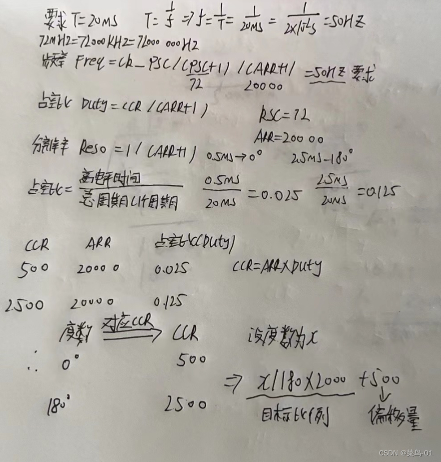
The steering gear is a device that controls the output angle according to the duty cycle of the input PWM signal.
Input PWM signal requirements: period is 20ms, high level width is 0.5ms~2.5ms

High level width = duration of a certain electric frequency
CCR=high electrical frequency
The control of the steering gear generally requires a 20ms time base pulse (period), and the high-level part of the pulse is generally the angle control pulse part in the range of 0.5ms~2.5ms. Taking the 180-degree angle servo as an example, the corresponding control relationship is as follows:
0.5ms--------------0 degrees;
1.0ms---------- -45 degrees;
1.5ms------------90 degrees;
2.0ms-----------135 degrees;
2.5ms----------- 180 degree;
3: Steps
1:RCC turns on the clock, (TIM peripherals---RCC_APB1PeriphClockCmd and GPIO peripherals--RCC_APB2PeriphClockCmd clocks are turned on)
2: Configure GPIO----GPIO_Init (write the second step last)
3: Clock selection----TIM_InternalClockConfig (internal)
4: Configure time base unit-----TIM_TimeBaseInit()
5: Configure the output comparison unit----TIM_OC2Init()
6: Start timer-----TIM_Cmd
4: Code
This uses the CH2 channel, and the LED above uses the CH2 channel.
Usage: TIM_SetCompareX and TIM_OCXInit functions are changed to the corresponding X value
X should be 2. See pin definition table below
#include "stm32f10x.h"                  // Device header
#include "Delay.h"
#include "OLED.h"
#include "Servo.h"
#include "Key.h"
void PWM_Init(void)
{
	RCC_APB1PeriphClockCmd(RCC_APB1Periph_TIM2, ENABLE);
	RCC_APB2PeriphClockCmd(RCC_APB2Periph_GPIOA, ENABLE);

	GPIO_InitTypeDef GPIO_InitStructure;
	GPIO_InitStructure.GPIO_Mode = GPIO_Mode_AF_PP; //复用推挽输出
	GPIO_InitStructure.GPIO_Pin = GPIO_Pin_1;
	GPIO_InitStructure.GPIO_Speed = GPIO_Speed_50MHz;
	GPIO_Init(GPIOA, &GPIO_InitStructure);

	TIM_InternalClockConfig(TIM2);

	TIM_TimeBaseInitTypeDef TIM_TimeBaseInitStructure;
	TIM_TimeBaseInitStructure.TIM_ClockDivision = TIM_CKD_DIV1;
	TIM_TimeBaseInitStructure.TIM_CounterMode = TIM_CounterMode_Up;
	TIM_TimeBaseInitStructure.TIM_Period = 20000 - 1;		//ARR
	TIM_TimeBaseInitStructure.TIM_Prescaler = 72 - 1;		//PSC
	TIM_TimeBaseInitStructure.TIM_RepetitionCounter = 0;
	TIM_TimeBaseInit(TIM2, &TIM_TimeBaseInitStructure);

	TIM_OCInitTypeDef TIM_OCInitStructure;
	TIM_OCStructInit(&TIM_OCInitStructure);
	TIM_OCInitStructure.TIM_OCMode = TIM_OCMode_PWM1;
	TIM_OCInitStructure.TIM_OCPolarity = TIM_OCPolarity_High;
	TIM_OCInitStructure.TIM_OutputState = TIM_OutputState_Enable;
	TIM_OCInitStructure.TIM_Pulse = 0;		//CCR
	TIM_OC2Init(TIM2, &TIM_OCInitStructure);

	TIM_Cmd(TIM2, ENABLE);
}

void PWM_SetCompare2(uint16_t Compare)
{
	TIM_SetCompare2(TIM2, Compare);
}


void Servo_Init(void)
{
	PWM_Init();
}

void Servo_SetAngle(float Angle)
{
	PWM_SetCompare2(Angle / 180 * 2000 + 500);
}


void Key_Init(void)
{
	RCC_APB2PeriphClockCmd(RCC_APB2Periph_GPIOB, ENABLE);

	GPIO_InitTypeDef GPIO_InitStructure;
	GPIO_InitStructure.GPIO_Mode = GPIO_Mode_IPU;
	GPIO_InitStructure.GPIO_Pin = GPIO_Pin_1 | GPIO_Pin_11;
	GPIO_InitStructure.GPIO_Speed = GPIO_Speed_50MHz;
	GPIO_Init(GPIOB, &GPIO_InitStructure);
}

uint8_t Key_GetNum(void)
{
	uint8_t KeyNum = 0;
	if (GPIO_ReadInputDataBit(GPIOB, GPIO_Pin_1) == 0)
	{
		Delay_ms(20);
		while (GPIO_ReadInputDataBit(GPIOB, GPIO_Pin_1) == 0);
		Delay_ms(20);
		KeyNum = 1;
	}
	if (GPIO_ReadInputDataBit(GPIOB, GPIO_Pin_11) == 0)
	{
		Delay_ms(20);
		while (GPIO_ReadInputDataBit(GPIOB, GPIO_Pin_11) == 0);
		Delay_ms(20);
		KeyNum = 2;
	}

	return KeyNum;
}

uint8_t KeyNum;
float Angle;

int main(void)
{
	OLED_Init();
	Servo_Init();
	Key_Init();

	OLED_ShowString(1, 1, "Angle:");

	while (1)
	{
		KeyNum = Key_GetNum();
		if (KeyNum == 1)
		{
			Angle += 30;
			if (Angle > 180)
			{
				Angle = 0;
			}
		}
		Servo_SetAngle(Angle);
		OLED_ShowNum(1, 7, Angle, 3);
	}
}
calculate
TIM_SetCompareX: A function to individually change the CCR register value, which can change the duty cycle
Pin definition table
The signal line of the servo is connected to PA1, so CH2 channel 2 is used, and X is 2; PA1 outputs PWM waveform.

C: PWM drive DC motor
1: Connection diagram

2: Motor and drive circuit
A DC motor is a device that converts electrical energy into mechanical energy. It has two electrodes. When the electrodes are connected positively, the motor rotates forward.
When the electrodes are reversed, the motor will reverse. DC motors are high-power devices and cannot be driven directly by the GPIO port. They need to be operated with a motor drive circuit. TB6612 is
a dual H-bridge type DC motor driver chip that can drive two DC motors. and control its speed and direction

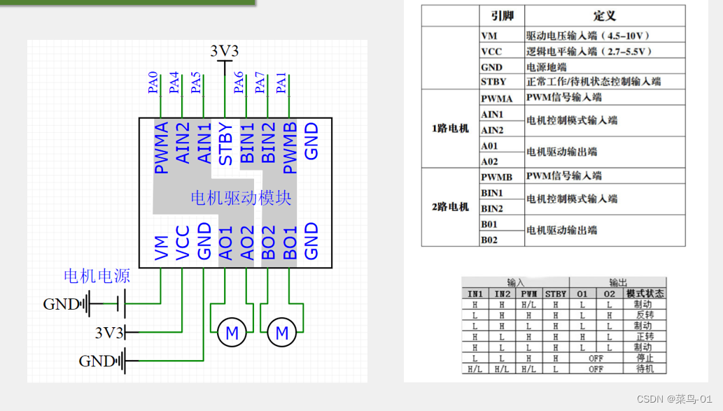
For details on motor drive, see: 51: Motor (ULN2003D)
3: Code
#include "stm32f10x.h"                  // Device header
#include "OLED.h"
#include "PWM.h"
#include "motor.h"
#include "Key.h"
void PWM_init(){
	//第一步,RCC开启时钟,把我们要用的TIM外设和GPIO外设的时钟打开
	RCC_APB1PeriphClockCmd(RCC_APB1Periph_TIM2,ENABLE);
	RCC_APB2PeriphClockCmd(RCC_APB2Periph_GPIOA,ENABLE);


	//第二步,配置GPIO
	GPIO_InitTypeDef GPIO_INITStruct;
	GPIO_INITStruct.GPIO_Mode=GPIO_Mode_AF_PP;  //复用推挽输出
	GPIO_INITStruct.GPIO_Pin=GPIO_Pin_2 ;
	GPIO_INITStruct.GPIO_Speed= GPIO_Speed_50MHz;
	GPIO_Init(GPIOA,&GPIO_INITStruct);
	//第三步,时钟源选择(内部时钟)
	TIM_InternalClockConfig(TIM2);
	//第四步,配置时基单元
	TIM_TimeBaseInitTypeDef TIM_INITStruct;
	TIM_INITStruct.TIM_ClockDivision=TIM_CKD_DIV1;
	TIM_INITStruct.TIM_CounterMode=TIM_CounterMode_Up;  向上计数
	TIM_INITStruct.TIM_Period=100-1;
	TIM_INITStruct.TIM_Prescaler=720-1;
	TIM_INITStruct.TIM_RepetitionCounter=0;
	TIM_TimeBaseInit(TIM2,&TIM_INITStruct);
	//第五步,配置输出比较单元
	TIM_OCInitTypeDef TIM_OCInitStructure;
	TIM_OCStructInit(&TIM_OCInitStructure);//给输出比较结构体赋一个默认的值
	TIM_OCInitStructure.TIM_OCMode = TIM_OCMode_PWM1; //选择PWM1的模式
	TIM_OCInitStructure.TIM_OCPolarity = TIM_OCPolarity_High; //有效电频为低电频
	TIM_OCInitStructure.TIM_OutputState = TIM_OutputState_Enable;  //使能
	TIM_OCInitStructure.TIM_Pulse = 0;		//CCR
	TIM_OC3Init(TIM2, &TIM_OCInitStructure);
	//第六步,启动定时器
	TIM_Cmd(TIM2,ENABLE);
}

void PWM_SetCompare3(uint16_t Compare)
{
	TIM_SetCompare3(TIM2, Compare);
}
void motor_init(){
	RCC_APB2PeriphClockCmd(RCC_APB2Periph_GPIOA,ENABLE);
	GPIO_InitTypeDef GPIO_INITstruct;
	GPIO_INITstruct.GPIO_Mode=GPIO_Mode_IPU;//GPIO_Mode_Out_PP  //GPIO_Mode_IPU
	GPIO_INITstruct.GPIO_Pin=GPIO_Pin_4|GPIO_Pin_5;
	GPIO_INITstruct.GPIO_Speed=GPIO_Speed_50MHz;
	GPIO_Init(GPIOA,&GPIO_INITstruct);
	PWM_init();
}

void motor_serspeed(int8_t speed){
	if(speed >=0){
		GPIO_SetBits(GPIOA,GPIO_Pin_5);  //高电频
		GPIO_ResetBits(GPIOA,GPIO_Pin_4); //低电频
		PWM_SetCompare3(speed);
	}
	else
	{
		GPIO_SetBits(GPIOA,GPIO_Pin_4);  //高电频
		GPIO_ResetBits(GPIOA,GPIO_Pin_5); //低电频
		//传穿过来的speed为负数,要变为正,所以要加一个负号;
		PWM_SetCompare3(-speed);
	}
}
void Key_Init(void)
{
	RCC_APB2PeriphClockCmd(RCC_APB2Periph_GPIOB, ENABLE);

	GPIO_InitTypeDef GPIO_InitStructure;
	GPIO_InitStructure.GPIO_Mode = GPIO_Mode_IPU;
	GPIO_InitStructure.GPIO_Pin = GPIO_Pin_1 | GPIO_Pin_11;
	GPIO_InitStructure.GPIO_Speed = GPIO_Speed_50MHz;
	GPIO_Init(GPIOB, &GPIO_InitStructure);
}

uint8_t Key_GetNum(void)
{
	uint8_t KeyNum = 0;
	if (GPIO_ReadInputDataBit(GPIOB, GPIO_Pin_1) == 0)
	{
		Delay_ms(20);
		while (GPIO_ReadInputDataBit(GPIOB, GPIO_Pin_1) == 0);
		Delay_ms(20);
		KeyNum = 1;
	}
	if (GPIO_ReadInputDataBit(GPIOB, GPIO_Pin_11) == 0)
	{
		Delay_ms(20);
		while (GPIO_ReadInputDataBit(GPIOB, GPIO_Pin_11) == 0);
		Delay_ms(20);
		KeyNum = 2;
	}

	return KeyNum;
}


uint8_t key_num;
int8_t speed;  //速度必须是有符号的
int main(void)
{
	Key_Init();
	OLED_Init();
	motor_init();

	OLED_ShowString(1,1,"speed:");

	while (1)

	{
		key_num=Key_GetNum();
		if (key_num==1){
			speed+=20;
			if(speed>100){
				speed=-100;
			}
		}
			motor_serspeed(speed);
			OLED_ShowSignedNum(1, 7, speed, 3);
	}


	}