/*
函数功能:定时器1通道1 4产生PWM波
函数参数:无
函数返回值:无
函数描述:无
*/
void Dingshiqi1_PWM_Init(void)
{

	TIM_TimeBaseInitTypeDef TIM_TimeBaseInitStruct;  //时间基 结构体变量
	GPIO_InitTypeDef GPIO_InitStruct;								//GPIO初始化 结构体变量
	TIM_OCInitTypeDef TIM_OCInitStruct;							//通道初始化 结构体变量

	RCC_APB2PeriphClockCmd(RCC_APB2Periph_TIM1,ENABLE); //使能TIM1定时器时钟线
	RCC_APB2PeriphClockCmd(RCC_APB2Periph_GPIOA,ENABLE);	//使能GPIOA时钟线

	TIM_TimeBaseInitStruct.TIM_ClockDivision = TIM_CKD_DIV1;  //这里跟TIM1 产生PWM波功能无关
	TIM_TimeBaseInitStruct.TIM_CounterMode = TIM_CounterMode_Up; //向上计时模式
	TIM_TimeBaseInitStruct.TIM_Period = 1000;    //计算到1000 那就是定时10ms
	TIM_TimeBaseInitStruct.TIM_Prescaler = 720;  //最高频率72MHZ  这里定义 预分频720

	TIM_TimeBaseInit(TIM1,&TIM_TimeBaseInitStruct);//初始化函数 让刚刚配置的参数 输入到对应寄存器里面

	GPIO_InitStruct.GPIO_Mode = GPIO_Mode_AF_PP; //GPIO采用复用推挽输出模式
	GPIO_InitStruct.GPIO_Pin = GPIO_Pin_8 | GPIO_Pin_11; //TIM1同时产生两路PWM波 在管脚a8 a11
	GPIO_InitStruct.GPIO_Speed = GPIO_Speed_50MHz;  //GPIO速度50MHZ

	GPIO_Init(GPIOA,&GPIO_InitStruct);  //初始化函数 让刚刚配置的参数 输入到对应寄存器里面

	TIM_OCInitStruct.TIM_OCMode = TIM_OCMode_PWM1; //PWM1模式
	TIM_OCInitStruct.TIM_OCPolarity = TIM_OCPolarity_High;//输出极性高
	TIM_OCInitStruct.TIM_OutputState = TIM_OutputState_Enable;//让捕获/比较寄存器使能
	TIM_OCInitStruct.TIM_Pulse = 0;  //初始化占空比0   占空比可以依照TIM_Period进行配置 在它范围内就好了

	TIM_OC1Init(TIM1,&TIM_OCInitStruct); //初始化函数 让刚刚配置的参数 输入到对应寄存器里面
	TIM_OC4Init(TIM1,&TIM_OCInitStruct); //初始化函数 让刚刚配置的参数 输入到对应寄存器里面
	TIM_Cmd(TIM1,ENABLE);    //使能定时器TIM1
	TIM_CtrlPWMOutputs(TIM1,ENABLE);  //确定让TIM1输入PWM
	TIM_OC1PreloadConfig(TIM1,ENABLE);  //让捕获/比较1寄存器 预装载功能使能 同时配置CC1通道为输出
	TIM_OC4PreloadConfig(TIM1,ENABLE); //让捕获/比较1寄存器 预装载功能使能 同时配置CC4通道为输出
	TIM_ARRPreloadConfig(TIM1,ENABLE);  //自动重装载预装载允许
}
Waveform plot generated by this code:
The duty cycle is: 300, TIM_OCInitStruct.TIM_Pulse = 300;
The yellow line is channel 1 and the purple line is channel 4.

Advanced Control Timer Block Diagram:

The above details:
Code description:
1. TIM_TimeBaseInitStruct.TIM_ClockDivision = TIM_CKD_DIV1; //This has nothing to do with the function of TIM1 generating PWM waves.
Reason: CKD[1:0]: Clock division factor (Clock division)
These 2 bits are defined in the timer clock (CK_INT) frequency, dead time and used by the dead time generator and digital filter (ETR, TIx
) Frequency division ratio between sampling clocks. ----- So irrelevant.
2.TIM_TimeBaseInitStruct.TIM_Period = 1000; //calculate to 1000, that is, the timing is 10ms
TIM_TimeBaseInitStruct.TIM_Prescaler = 720; //The highest frequency is 72MHZ, here defines the prescaler frequency 720
Reason: According to the stm32f1xx reference manual, the clock frequency of the counter (CK_CNT) is equal to fCK_PSC/(PSC[15:0]+1). So here 719 is 720 frequency division. Timing 10ms is calculated as follows: 10ms=(1/(72/720)*1000)s*(10^(-6)).
3. TIM_OCInitStruct.TIM_OutputState = TIM_OutputState_Enable;//Enable the capture/compare register
After the judgment of the oscilloscope, it is found that whether this parameter is enabled or not, it will not affect the output of the OC1 channel, but it will affect the output of other channels. (If you find the reason, please comment, thank you)
When TIM_OutputState_Enable: the oscilloscope is as shown above.
TIM_OutputState_Disable时:

3. Careful friends also found that there are several parameters under the TIM_OCInitStruct structure (the functions are as follows):
1. TIM_OCInitStruct.TIM_OCNIdleState
2.TIM_OCInitStruct.TIM_OCNPolarity
3. TIM_OCInitStruct.TIM_OutputNState
TIM_OCInitStruct.TIM_OCNIdleState This parameter has nothing to do with PWM output. It is used for braking and dead zone registers through the reference manual.
TIM_OCInitStruct.TIM_OCNPolarity This parameter can change the output polarity of channel 1, which is not well understood at present (why there is a complementary output polarity there).
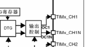
The TIM_OCInitStruct.TIM_OutputNState parameter determines whether the TIMX_CH1N channel is output. Like the place pictured above.
In addition, these three parameters are only related to the advanced timer. If you do not use the advanced timer, you can leave it alone and let it be configured by default.