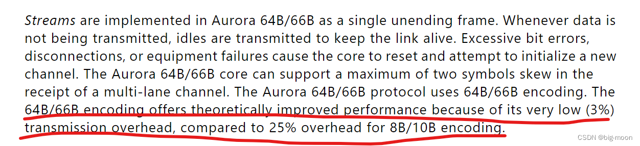
There are two types of Aurora8B10B and Aurora64B66B for Aurora. The main difference between Aurora8B10B and Aurora64B66B is that 8B/10B encoding can balance DC and have enough jumps to recover the clock, but there is a 25% bandwidth overhead. The first two bits of 64B/66B encoding represent the synchronization header, which reduces overhead, but cannot guarantee the balance of the number of 0/1, so scrambling is required.
You can choose according to actual project needs. I used Aurora64B66B to design, so this article mainly explains the IP, mainly referring to the PG074 document provided by Xilinx for explanation.
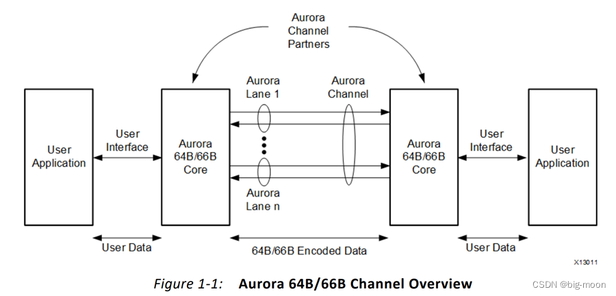
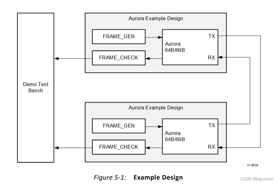
The above figure shows a schematic diagram of Aurora IP channel transmission. As can be seen from the way, there are Channels and Lanes between the two Aurora IP cores, and the transmission channel contains several Lanes. The transmission and exchange of data is achieved through this model. For this IP core, it is actually the most basic application of the Serders interface, so you can directly configure the IP core and then use the official Demo provided by Xilinx for simulation.
The internal block diagram of the IP core is as follows:
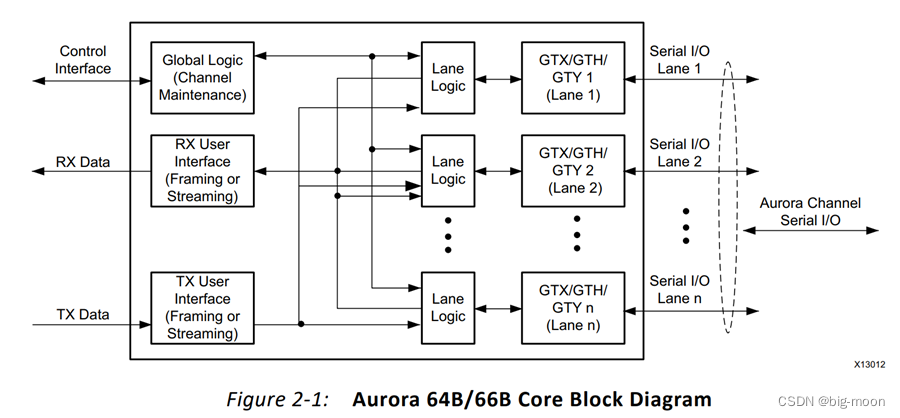
The main functional modules of the Aurora 64B/66B core are:
•Lane Logic: An instance of the lane logic module drives each GT transceiver. The channel logic initializes each individual transceiver, handles encoding and decoding of control characters, and performs error detection.
•Global Logic: The global logic module in the core performs channel binding for channel initialization. During operation, the channel tracks the not-ready idle characters defined by the Aurora 64B/66B protocol and monitors all channel logic modules for errors.
•RX User Interface: The AXI4 Stream Receive (RX) user interface moves data from the channel to the application and performs flow control functions.
•TX User Interface: The AXI4 Streaming (TX) user interface moves data from the application to the channel and performs flow control TX functions. The standard clock compensation module is embedded inside the core. This module controls the periodic transmission of clock compensation (CC) characters.
Without further ado, let’s go straight to the IP configuration.
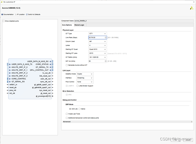
Similarly, in the design, the rate and the number of Lanes can be configured according to actual needs, but DRP Mode recommends choosing AXI4 Lite, which facilitates later data transmission and the integration of the IP into other projects. After the configuration is completed, directly open the demo provided by Xilinx, and then click Simulation to start the simulation of the IP core.
Demo model of IP
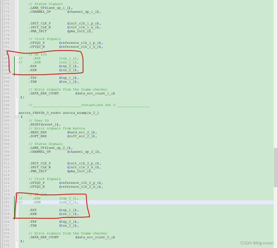
In the design, the author made small modifications to the TX core RX, as shown in the red circle in the figure below. The annotated content in the red circle is the original connection in the Demo. The modifications I made are mainly to adapt to the TX core RX cross-connection when the two Auroras communicate with each other in the picture above, so as to achieve communication between the two IPs. That is, TX1->RX2, TX2->RX1, (I think this is the case. If I am wrong, I hope you will correct me. It turns out that whether the parts I modified have no impact on the simulation results.) Go directly to the simulation diagram: From
the
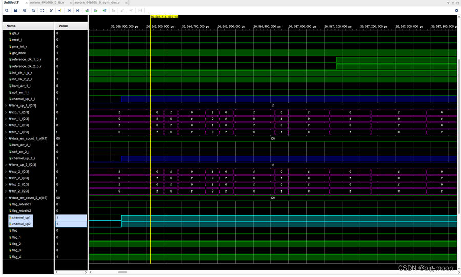
simulation It can be seen from the timing diagram that the rose red part is mainly the data of the TX core and RX. It can be seen that the data sent and the data received are actually the same, which is also in line with the actual situation of transmission. For the IP core, it has its own check signal, which can be seen from the blue signal. Channel_up requires all Lane_up to be locked before it can be judged that the channel communicates normally, which is also in line with the transmission logic. Where Channel_up is 1, it indicates that the verification sequence is successful, and Lane_up is 1, which indicates that the communication link training between the transceivers is successful. The green part has the same Channel_up function as the blue part, just to indicate normal transmission of the channel.
Of course, the simulation results can also be judged through the following signals:
| Interface name | describe |
|---|---|
| core error signals | Aurora 64B/66B core status and control interface error signals are brought to the top level of the example design and registered to represent core runtime error signal flags |
| core lane up | |
| signals | The core channel up status signals are brought to the top level of the example design and registered. The core has a channel upstream signal for each GTX and GTH transceiver they use. |
| core channel up signals | The core's channel upstream status signal is brought to the top level of the sample design and registered, indicating whether the signal in the channel is UP when the core is running. |
| data_err_count[0:7] | frame_CHECK Count of received frame data words that do not match expected values |