Task objective: Master the method of configuring the timer to output PWM signal in CubeMX software.
Task content: use the PWM signal to control the indicator LED on the development board. Set the PWM period to 20 ms, the duty cycle starts from 0%, and the step is 10%. After incrementing to 100%, start at 0% and repeat the process. The time interval for duty cycle modification is 100 ms.
Task fulfillment:
1. Design ideas
Define 2 variables: duty cycle Duty and step value Step. The duty cycle is stepped from 0 to 100% step by step, the step ratio is 10%, and the step time interval is 100 ms. The period of the PWM signal is 20ms, the timing clock TIM2_CLK of the timer 14 is 84MHz, the prescaler coefficient PSC can be set to 84-1, and the automatic reload value ARR is 20000-1.
Since the duty cycle starts from 0, write the initial value of the capture/compare register TIM14_CCR1 to 0, and then call the capture/compare register setting macro function __HAL_TIM_SetCompare() in the while(1) loop to modify the contents of the register, starting from 0 , gradually increase, and repeat the process.
2. Implementation process
Using the board is a punctual atom explorer.
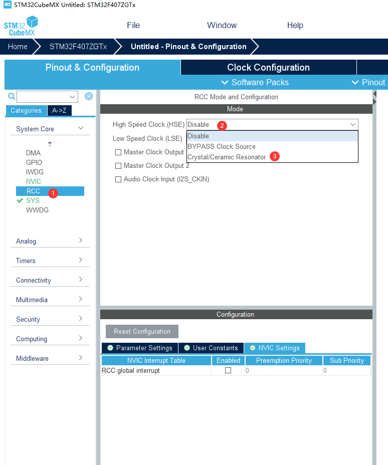
The first step is to set the system clock

Step Two: Configure the Pins

PF9 is the multiplexing pin of LED light and TIM14, so set TIM14 as the timer of PWM.
The third step is to set the timer TIM14
TIM14 is connected to the APB1 bus, and the clock of the APB1 bus is 84MHz. The period of PWM is 20ms, so set PSC=84-1, ARR=20000-1, duty cycle pulse=0; enable the preload function.

The fourth step, generate code


The fifth step, write code
/* USER CODE BEGIN 2 */
	uint16_t Duty=0;
	uint16_t step=2000;//定义占空比和步进值 step=20000*10%=2000

	HAL_TIM_PWM_Start(&htim14,TIM_CHANNEL_1);
  /* USER CODE END 2 */

  /* Infinite loop */
  /* USER CODE BEGIN WHILE */
  while (1)
  {
		for(Duty=0;Duty<=20000;Duty=Duty+step)
		{
			__HAL_TIM_SetCompare(&htim14,TIM_CHANNEL_1,Duty);
			HAL_Delay(100);
		}
    /* USER CODE END WHILE */

    /* USER CODE BEGIN 3 */

  }
  /* USER CODE END 3 */
operation result:
Compile and link the program to generate executable code, download it to the development board through the ST-Link emulator, you can observe that the indicator LED starts from the off state, and the brightness gradually increases, and repeat the process.