Article Directory
foreword
Environment:
1. Quartus18.0
2. vscode
3. Board model: EP4CE10F17C8
4. Ultrasonic module: HC_SR04
Requirements:
use EP4CE10F17C8 development board to drive the ultrasonic detection module (HC_SR04), and display the measured data on the serial port assistant.
1. Ultrasonic module introduction
1. Product Features
HC-SR04 ultrasonic ranging module can provide 2cm-400cm non-contact distance sensing function, and the ranging accuracy can reach as high as 3mm; the module includes ultrasonic transmitter, receiver and control circuit.
Basic working principle:
(1) Use IO port TRIG to trigger ranging, and give a high level signal of at least 10us.
(2) The module automatically sends 8 square waves of 40khz, and automatically detects whether there is a signal return;
(3) If there is a signal return, a high level is output through the IO port ECHO, and the duration of the high level is the time from the transmission to the return of the ultrasonic wave. time. Test distance = (high level time * speed of sound (340M/S))/2;

2. The timing diagram of the ultrasonic module
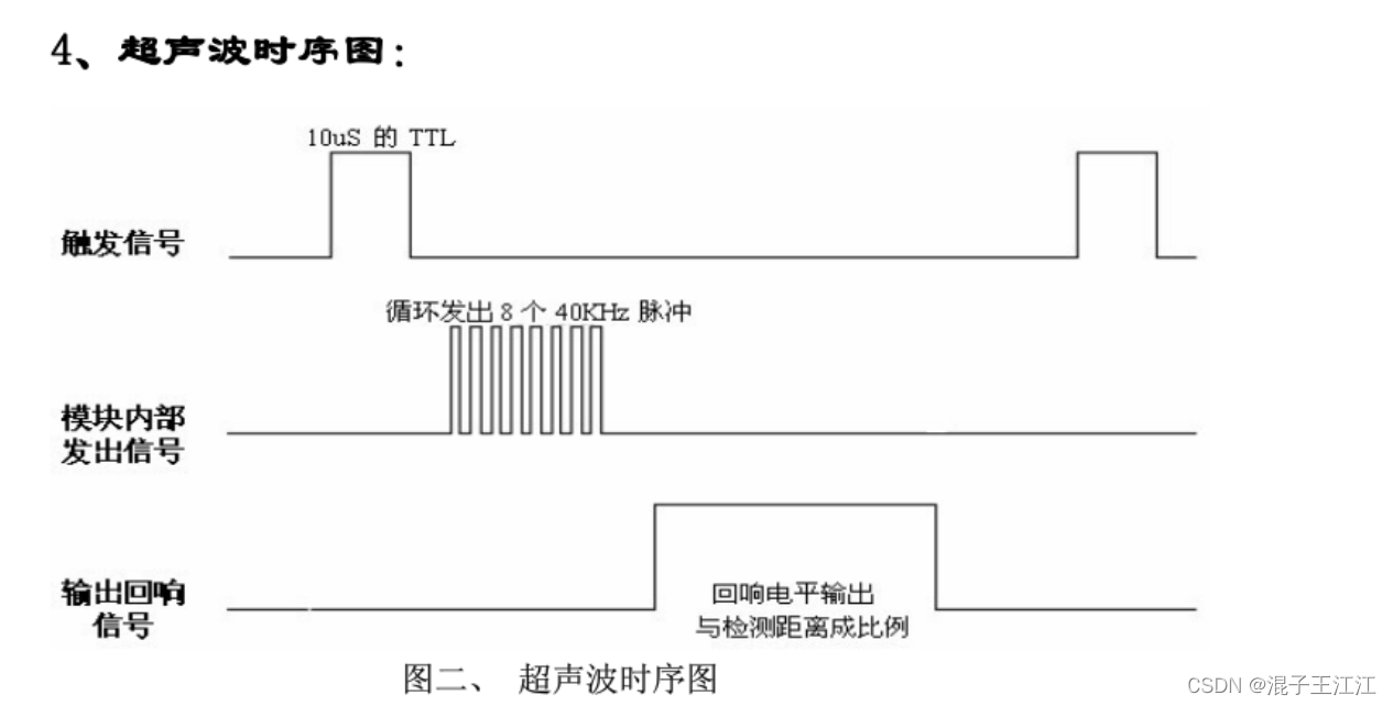
The above timing diagram shows that you only need to provide a pulse trigger signal of more than 10uS, and the module will internally send out 8 40kHz periodic levels and detect echoes. Once an echo signal is detected, an echo signal is output. The pulse width of the echo signal is proportional to the measured distance. Thus the distance can be calculated from the time interval between sending the signal and receiving the echo signal.
2. System design
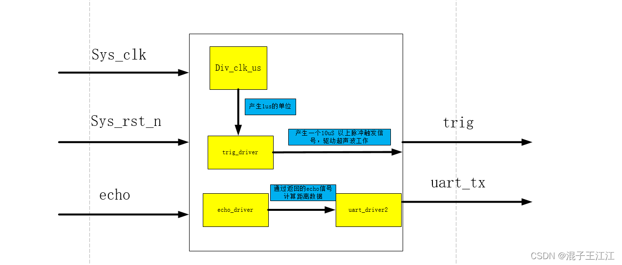
1. System module block diagram
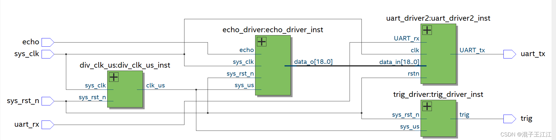
2. RTL view
3. Source code
1. div_clk_us (frequency division of 1us)
/**************
芯片晶振为50MHZ,HC_SR04需要一个10us的以上脉冲触发信号
所以这里我们需要对系统时钟进行分频,方便我们产生10us的持续电平
**************/
module div_clk_us (
    input sys_clk,
    input sys_rst_n,

    output wire  clk_us
);

//根据晶振换算,1us只需要计数50次即可

parameter [5:0] MAX_us = 6'd49;
reg [5:0] cnt;
always @(posedge sys_clk or negedge sys_rst_n) begin
    if(!sys_rst_n)begin
        cnt <= 6'd0;
    end
    else if(cnt == MAX_us)begin
        cnt <= 6'd0;
    end
    else begin
        cnt <= cnt + 6'd1;
    end
end
assign clk_us = cnt >= MAX_us;
endmodule
2. Generate a signal to drive the ultrasonic wave
/****************
根据分频的1us时钟,产生一个持续10us的电平用于驱动HC_SR04
最好是稍微大于10us,这样稳妥一些
****************/
module trig_driver(
    input       sys_us        ,//1us时钟
    input       sys_rst_n     ,

    output      trig          //驱动超声波的信号
);

parameter T = 19'd29_9999;//设置触发信号的周期,这里设置得越小,其触发越频繁,应该返回的距离更新更频繁

reg [18:0] cnt;

always @(posedge sys_us) begin// or negedge sys_rst_n
    if(!sys_rst_n)begin
        cnt <= 19'd0;
    end
    else if(cnt == T)begin
        cnt <= 19'd0;
    end
    else begin
        cnt <= cnt + 1'd1;
    end
end
//15us的高电平
assign trig = (cnt <15 ) ? 1'b1 : 1'b0;//正确的,只是时间太短,观察不到,目前应该是串口问题
endmodule
3. Serial sending module
module uart_send
#(
    parameter  CLK        =   26'd50000000    ,    // 时钟频率
    parameter  BAUD        =   17'd115200           // 波特率
)
(
    input   wire            clk         ,
    input   wire            rstn        ,
    input   wire    [7 : 0] data_in     ,   // 需要发送的数据
    input   wire            flag_in     ,   // 数据接收标志位,既发送标志位

    output  wire            tx_done     ,
    output  reg             UART_tx         // 串口输出位
);

    localparam Baud_Clk     =   CLK/BAUD       ;    // 传输每个 Baud 需要的时钟数

    reg             tx_en       ;   // 发送使能
    reg             flag_bit    ;   // 比特标志位,采用下降沿发送
    reg [8 : 0]     cnt_baud    ;   // 波特率计数器
    reg [3 : 0]     cnt_bit     ;   // 比特计数器

    assign tx_done = cnt_bit == 4'd9 && flag_bit == 1'b1;

    // 发送使能
    always @(posedge clk or negedge rstn) begin
        if(!rstn) begin
            tx_en <= 1'b0;
        end
        // 已经发送了十位 bit 并且到达下一个下降沿,输入只需要判断到数据位最后一位,输出则需要判断完整输出
        else if(cnt_bit == 4'd9 && flag_bit == 1'b1) begin
            tx_en <= 1'b0;
        end
        else if(flag_in == 1'b1) begin
            tx_en <= 1'b1;
        end
    end

    // 波特计数器
    always @(posedge clk or negedge rstn) begin
        if(!rstn) begin
            cnt_baud <= 9'd0;
        end
        // 传输完成所有波特或者使能失效,表示发送结束
        else if(cnt_baud == Baud_Clk - 1'b1 || tx_en == 1'b0) begin
            cnt_baud <= 9'd0;
        end
        else begin
            cnt_baud <= cnt_baud + 9'd1;
        end
    end

    always @(posedge clk or negedge rstn) begin
        if(!rstn) begin
            flag_bit <= 1'b0;
        end
        // 只有刚开始发送的一瞬间会产生一个时钟周期上升沿和下降沿
        else if(cnt_baud == 9'd1) begin
            flag_bit <= 1'b1;
        end
        else begin
            flag_bit <= 1'b0;
        end
    end

    // 计数10分有效数据位
    always @(posedge clk or negedge rstn) begin
        if(!rstn) begin
            cnt_bit <= 4'd0;
        end
        // 已经发送了十位 bit 并且到达下一个下降沿
        else if(cnt_bit == 4'd9 && flag_bit == 1'b1) begin
            cnt_bit <= 4'd0;
        end
        // 使能有效,下降沿发送数据
        else if(flag_bit == 1'b1 && tx_en == 1'b1) begin
            cnt_bit <= cnt_bit + 4'd1;
        end
        else begin
            cnt_bit <= cnt_bit;
        end
    end

    // 满足 RS232 协议 起始位为 0,停止位为 1,并按位输出
    always @(posedge clk or negedge rstn) begin
        if(!rstn) begin
            UART_tx <= 1'd1;
        end
        // 下降沿发送数据
        else if(flag_bit == 1'b1) begin
            case (cnt_bit)
                0:       UART_tx <= 1'd0        ;
                1:       UART_tx <= data_in[0]  ;
                2:       UART_tx <= data_in[1]  ;
                3:       UART_tx <= data_in[2]  ;
                4:       UART_tx <= data_in[3]  ;
                5:       UART_tx <= data_in[4]  ;
                6:       UART_tx <= data_in[5]  ;
                7:       UART_tx <= data_in[6]  ;
                8:       UART_tx <= data_in[7]  ;
                9:       UART_tx <= 1'd1        ;
                default: UART_tx <= 1'd1        ;
            endcase
        end
    end
endmodule //UART_send
4. HC_SR04_uart (top-level file)
module HC_SR04_uart(
    input               sys_clk       ,
    input               sys_rst_n     ,
    input               echo          ,
    input        		uart_rx		  , // 串口输入

    output              trig          ,
    output              uart_tx       //串口发送端口
);
wire             clk_us;
wire [18:0]      data_o_r;//待发送的数据
//时钟分频
div_clk_us div_clk_us_inst(
    /*input */      .sys_clk         (sys_clk  ),
    /*input */      .sys_rst_n       (sys_rst_n),

    /*output*/      .clk_us          (clk_us)
);
//产生驱动超声波信号
trig_driver trig_driver_inst(
    /*input */      .sys_us        (clk_us),//1us时钟
    /*input */      .sys_rst_n     (sys_rst_n),

    /*output*/      .trig          (trig)//驱动超声波的信号
);
//对返回来的echo信号进行计算得出距离
echo_driver echo_driver_inst(
    /*input        */   .sys_clk         (sys_clk),
    /*input        */   .sys_us          (clk_us),
    /*input        */   .sys_rst_n       (sys_rst_n),
    /*input        */   .echo            (echo),

    /*output [18:0]*/   .data_o          (data_o_r)//检测距离,保留三位小数,*1000实现
);
//初步想法是使用串口发送模块直接操作,不需要串口回环,否则需要发送到接收,接收模块再发送给发送模块,发送模块再发送给PC
uart_driver2 uart_driver2_inst(
	.clk         (sys_clk  ),
	.rstn        (sys_rst_n),
	.data_in	 (data_o_r	),
    .UART_rx     (uart_rx),

	.UART_tx     (uart_tx	)
);
endmodule
4. Effect
FPGA serial port output ranging information
V. Summary
I wrote about the digital tube display of FPGA ranging, and the output of the ranging serial port of STM32. In fact, the content of this article has been completed before. Since I learned one side of the serial port loopback earlier, I typed it again to realize the serial port output of the FPGA. Although I did it, I still struggled for a day, and the simulation and SignalTap II captured the signal all afternoon. But this time the understanding was deeper than last time, and I gained more.
6. References
1. Ultrasonic ranging based on FPGA - digital tube display
2. Source code: https://github.com/no1jiangjiang/HC-SR04_uart_FPGA