The following is an abstract assembly instruction
load a to r1
load b to r2
mult r1 r2 to r3
The first statement is why it is called an abstract assembly instruction here because we assume that there are infinitely many registers and we can always r1 r2 r3 r4... We call these registers virtual registers (virtual registers) and the work of register allocation in the backend is Map these virtual registers to real registers.
Secondly, it is found that both r1 and r2 store real variables (variables) a and b, while r3 is a transitory temporary variable (temporaries). The actual assembly does not have the concept of variables. Actually only registers and memory addresses
In the optimization process, for example, common subexpression elimination (CSE) will increase the number of variables to reduce repeated calculations. Once there are too many variables, the burden on registers will be increased, resulting in some variables not being stored in the fastest registers but stored in memory. It may backfire and slow down the code execution speed
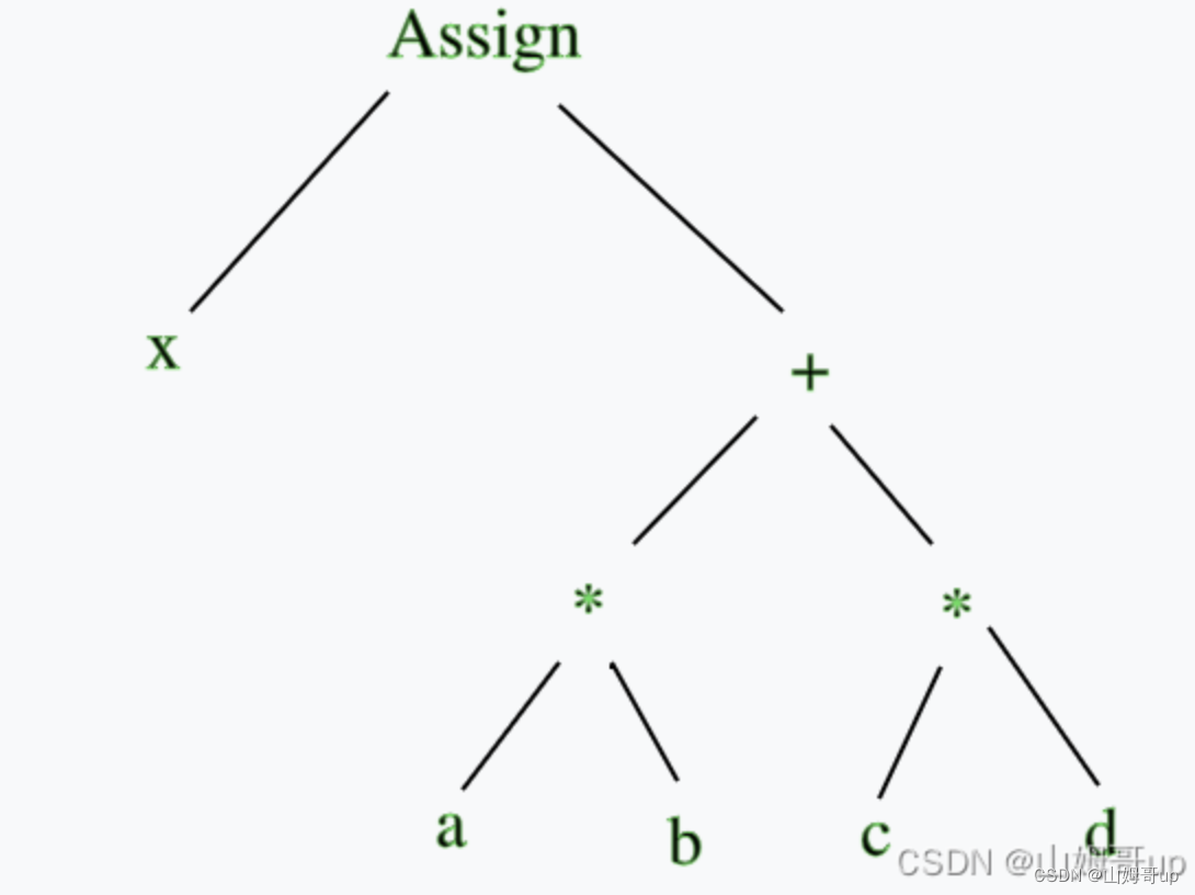
How to convert an AST into an abstract assembly instruction? Here is a feature that is deep first. Only the bottom-level a*b and c*d can be calculated before the addition operation of the upper layer can be performed. Only after the addition operation can the assignment operation be performed.
ILOC (intermidate language for optimizing compiler) compiler optimized intermediate language
load a
r1
loadAI
, @a
//The first line of abstract assembly instructions is actually a simplification of the second line The second line is the complete way of writing abstract assembly instructions
// but usually abbreviated
A stands for address, I stands for immediate, and loadAI together means to load the address immediately. It stands for activation record pointer. @a stands for offset.

Here you can see an activity record, often called a stack frame (stack frame). The main function calls the f1 function. The f1 function internally calls f2. There is a variable abc in f2, which is 0xff00, which acts as a segment register, and @a is the offset. The role of the instruction pointer register
register allocation
Suppose we have three physical registers p1 p2 p3 to allocate all virtual registers to physical registers
First add an extra blue part

Obviously, a longer life cycle corresponds to greater pressure on registers
When the last line is removed and the blue color is darkened
It can be seen that the register allocation function of the backend will try to use as few registers as possible to do calculations. Only when the life cycle of the data in other registers is not over will new registers be used.
What if there are only two physical registers p1 and p2?

It can be seen that when there are only two physical registers, each virtual register cannot be mapped to a physical register, but needs to be temporarily stored in memory. In this case, it is called spill in English, which means overflowing into memory. Register allocation will be as much as possible. Avoid spills