RISCV-3 RV32I/RV64I basic integer instruction set
- 1 RV32I Base Integer Instruction Set
-
- 1.1 Programmers’ Model for Base Integer ISA
- 1.2 Base Instruction Formats
- 1.3 Immediate Encoding Variants
- 1.4 Integer Computational Instructions
- 1.5 Control Transfer Instructions
- 1.6 Load and Store Instructions
- 1.7 Memory Ordering Instructions
- 1.8 Environment Call and Breakpoints
- 1.9 HINT Instructions
- 2 RV64I Base Integer Instruction Set
- reference documents
RISCV - 1 RV32/64G Instruction Set List
RISCV - 2 “Zicsr“, CSR Instructions
1 RV32I Base Integer Instruction Set
1.1 Programmers’ Model for Base Integer ISA
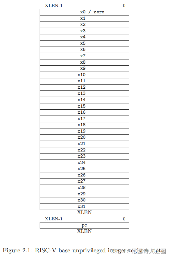
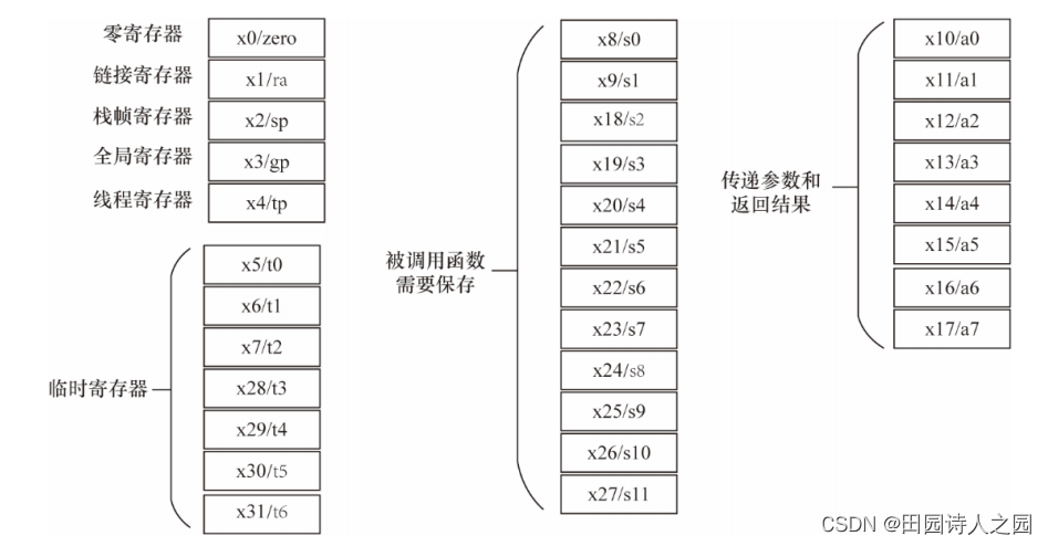
Figure 2.1 shows the unprivileged state for the base integer ISA. For RV32I, the 32 x registers are each 32 bits wide, ie, XLEN=32. Register x0 is hardwired with all bits equal to 0. General purpose registers x1–x31 hold values that various instructions interpret as a collection of Boolean values, or as two's complement signed binary integers or unsigned binary integers.
Figure 2.1 shows the unprivileged state of the basic integer ISA. For RV32I, each of the 32 x registers is 32 bits wide, ie XLEN=32. General purpose registers x1-x31 hold values that are interpreted by various instructions as a set of Boolean values, signed binary integers, or unsigned binary integers.
There is one additional unprivileged register: the program counter pc holds the address of the current instruction
.
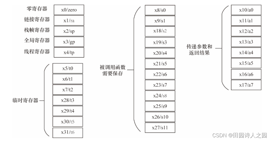
Register function classification of RC32I:
There is no dedicated stack pointer or subroutine return address link register in the Base Integer ISA; the instruction encoding allows any x register to be used for these purposes. However, the standard software calling convention uses register x1 to hold the return address for a call , with register x5 available as an alternate link register. The standard calling convention uses register x2 as the stack pointer.
In the base integer ISA, there is no dedicated stack pointer or subroutine return address link register; the instruction encoding allows any x register to be used as the stack pointer for these purposes. However, standard software call convention uses register x1 to hold the return address of the call, and register x5 can be used as an alternate link register. The standard calling convention uses register x2 as the stack pointer.
Hardware might choose to accelerate function calls and returns that use x1 or x5.
Hardware might choose to accelerate function calls and returns that use x1 or x5.
The optional compressed 16-bit instruction format is designed around the assumption that x1 is the return address register and x2 is the stack pointer. Software using other conventions will operate correctly but may have greater code size. The optional compressed 16-bit instruction format
is Designed based on the assumption that x1 is the return address register and x2 is the stack pointer. Software using other conventions can also run normally, but the amount of code may be larger.
1.2 Base Instruction Formats
In the base RV32I ISA, there are four core instruction formats (R/I/S/U), as shown in Figure 2.2. All are a fixed 32 bits in length and must be aligned on a four-byte boundary in memory. instruction-address-misaligned exception is generated on a taken branch or unconditional jump if the target address is not four-byte aligned. This exception is reported on the branch or jump instruction, not on the target instruction. No instruction-address-misaligned exception is generated for a conditional branch that is not taken.
In the basic RV32I ISA, there are four core instruction formats (R/I/S/U), as shown in Figure 2.2. All instructions are a fixed 32 bits in length and must be aligned on four-byte boundaries in memory. An instruction address misalignment exception is generated when a branch or unconditional jump is executed if the target address is not quad-aligned. It is the branch or jump instruction that reports the exception, not the target instruction. A conditional branch that is not taken does not generate an instruction address alignment exception.
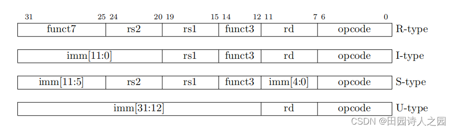
Figure 2.2: RISC-V base instruction formats. Each immediate subfield is labeled with the bit position (imm[x ]) in the immediate value being produced, rather than the bit position within the instruction's immediate field as is usually done. Figure 2.2
: RISC-V basic instruction format. Each immediate subfield is labeled with the bit position of the immediate being generated (imm[x]), rather than the usual bit position in the immediate field of the instruction.
1.3 Immediate Encoding Variants
There are a further two variants of the instruction formats (B/J) based on the handling of immediates, as shown in Figure 2.3
. Variants.
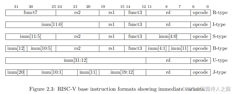
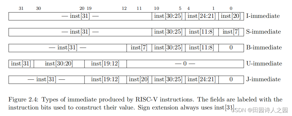
Figure 2.4 shows the immediates produced by each of the base instruction formats, and is labeled to show which instruction bit (inst[y ]) produces each bit of the immediate value
. It also marks the instruction bit (inst[y ]) that generates each bit of the immediate value.
1.4 Integer Computational Instructions
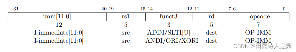
Most integer computational instructions operate on XLEN bits of values held in the integer register file. Integer computational instructions are either encoded as register-immediate operations using the I-type format or as register-register operations using the R-type format. The destination is register rd for both register-immediate and register-register instructions. No integer computational instructions cause arithmetic exceptions.
Most integer computational instructions operate on XLEN bit values in the integer register file. Integer arithmetic instructions are encoded either as register-to-literal operations using I-type format or as register-to-register operations using R-type format. Whether it is an immediate-register instruction or a register-register instruction, the target register is register rd. Integer arithmetic instructions do not cause arithmetic exceptions.
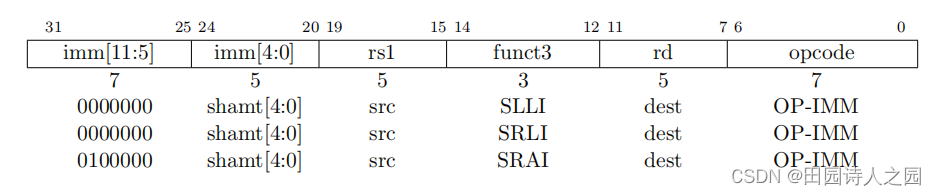
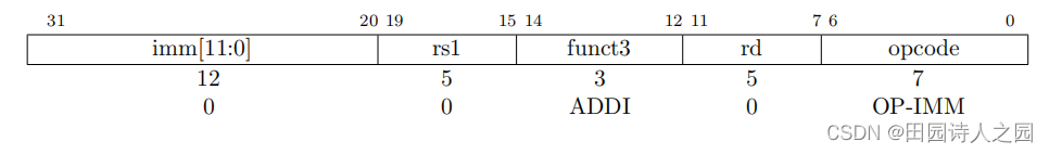
1.4.1 Integer Register-Immediate Instructions

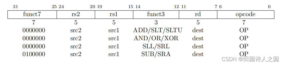
1.4.2 Integer Register-Register Operations
1.4.3 NOP Instruction
The NOP instruction does not change any architecturally visible state, except for advancing the pc and incrementing any applicable performance counters. NOP is encoded as ADDI x0, x0, 0. In addition to advancing the pc and incrementing any applicable performance counters, the NOP instruction does
not Change any architecturally visible state. NOPs are encoded as ADDI x0, x0, 0.
1.5 Control Transfer Instructions
RV32I provides two types of control transfer instructions: unconditional jumps and conditional branches
. Control transfer instructions in RV32I have no architecturally visible delay slots.
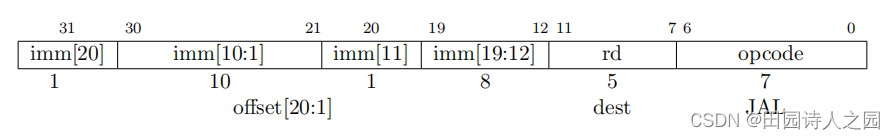
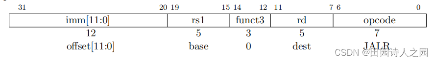
1.5.1 Unconditional Jumps
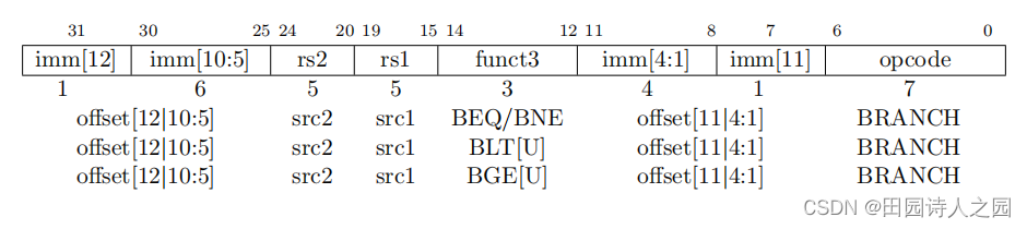
1.5.2 Conditional Branches
1.6 Load and Store Instructions
RV32i is a load-store Architecture, where only load and store instructions accesse manory and association of operation on CPU registers. Rv32i Provi. des a 32-bit address space that is byte-addressed. legal to access with which instructions (eg, some addresses might be read only, or support word access only). Loads with a destination of x0 must still raise any exceptions and cause any other side effects even though the load value is discarded. RV32I
Yes A load-store architecture in which only load and store instructions can access memory, and arithmetic instructions can only operate on CPU registers. RV32I provides a byte-addressable 32-bit address space. The EEI will define which parts of the address space are legally accessible with which instructions (for example, some addresses may only allow reads, or only support word accesses). A load with target address x0, even if the loaded value is discarded, must still raise any exceptions and cause any other side effects.
The EEI will define whether the memory system is little-endian or big-endian. In RISC-V, endianness is byte-address invariant. EEI will define whether the
memory system is little-endian or big-endian . In RISC-V, byte addresses do not change.
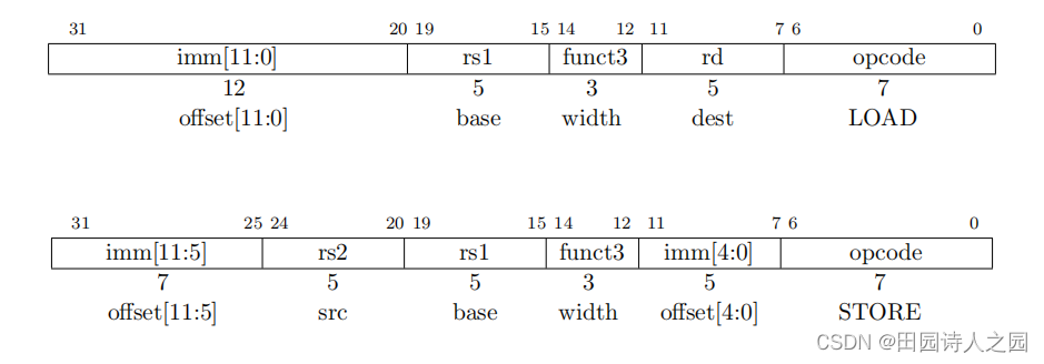
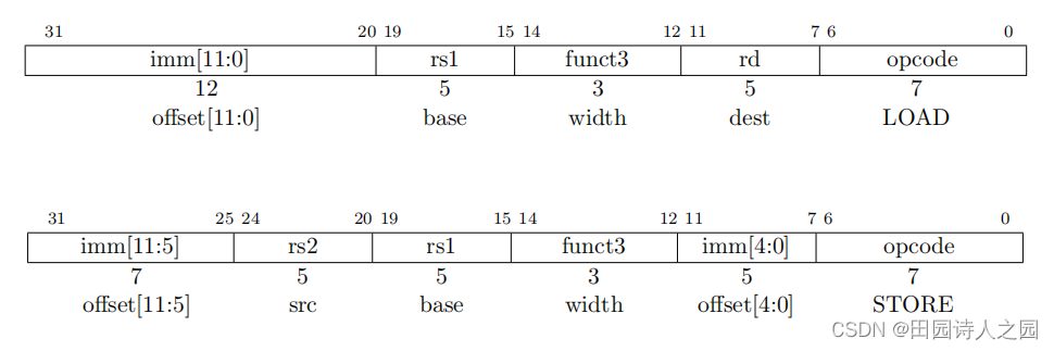
Load and store instructions transfer a value between the registers and memory. Loads are encoded in the I-type format and stores are S-type. The effective address is obtained by adding register rs1 to the sign-extended 12-bit offset. Loads copy a value from memory to register rd. Stores copy the value in register rs2 to memory.
Load and store instructions transfer values between registers and memory. Type I encoding is used for loading and Type S encoding is used for storage. The effective address is obtained by adding a sign-extended 12-bit offset to register rs1. load copies the value in memory into register rd. A store copies the value in register rs2 to memory.
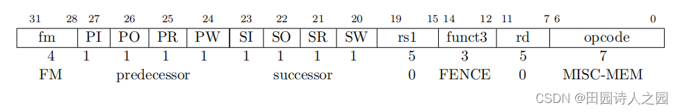
1.7 Memory Ordering Instructions
1.8 Environment Call and Breakpoints
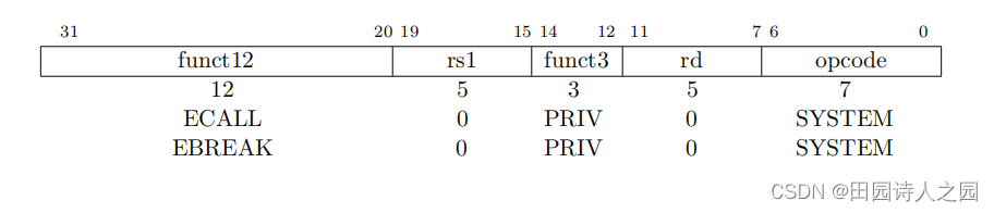
These two instructions cause a precise requested trap to the supporting execution environment
.
The ECALL instruction is used to make a service request to the execution environment. The EEI will define how parameters for the service request are passed, but usually these will be in defined locations in the integer register file. The ECALL instruction is used to issue
a Request for service. The EEI will define how the parameters of the service request are passed, but generally these parameters will be placed in the positions defined in the integer register file.
The EBREAK instruction is used to return control to a debugging environment.
The EBREAK instruction is used to return control to a debugging environment.
ECALL and EBREAK were previously named SCALL and SBREAK. The instructions have the same functionality and encoding, but were renamed to reflect that they can be used more generally than to call a supervisor-level operating system or debugger.
ECALL and EBREAK were formerly known as SCALL and SBREAK. These two instructions have the same function and encoding, but were renamed to reflect their broader use than invoking a supervisory-level operating system or debugger.
1.9 HINT Instructions
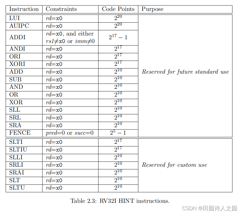
RV32I reserves a large encoding space for HINT instructions, which are usually used to communicate performance hints to the microarchitecture. HINTs are encoded as integer computational instructions with rd=x0. Hence, like the NOP instruction, HINTs do not change any architecturally visible state, Except for advancing the pc and any applicable performance counters. Implementations are always allowed to ignore the encoded hints.
RV32I reserves a large encoding space for HINT instructions, typically used to convey performance hints to the microarchitecture. HINT is encoded as an integer arithmetic instruction with rd=x0. Thus, like a NOP instruction, a HINT does not change any architecturally visible state other than advancing the pc and any applicable performance counters. In any case, the executor is allowed to ignore encoded hints.
Table 2.3 lists all RV32I HINT code points. 91% of the HINT space is reserved for standard HINTs, but none are presently defined. The remainder of the HINT space is reserved for custom HINTs: no standard HINTs will ever be defined in this subspace.
Table 2.3 lists all RV32I HINT code points. 91% of the HINT space is reserved for standard HINTs, but no standard HINTs are currently defined. The remainder of the HINT space is reserved for custom HINTs: this subspace will not define any standard HINTs.
2 RV64I Base Integer Instruction Set
2.1 Register State
RV64I widens the integer registers and supported user address space to 64 bits (XLEN=64).
RV64I widens the integer registers and supported user address space to 64 bits (XLEN=64).

RV64I register function classification:
2.2 Integer Computational Instructions
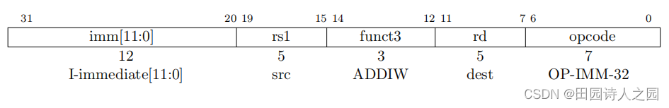
Most integer computational instructions operate on XLEN-bit values. Additional instruction variants are provided to manipulate 32-bit values in RV64I, indicated by a 'W' suffix to the opcode. Most integer computational instructions operate on XLEN-bit values
. In RV64I, other instruction variants are provided to operate on 32-bit values with the opcode suffix "W". These “*W” instructions ignore the upper 32 bits of their inputs and always produce 32
-bit signed values, ie bits XLEN-1 through 31 are equal.
Bit signed value, ie XLEN-1 to 31 bits equal.
2.2.1 Integer Register-Immediate Instructions
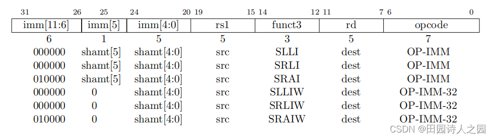

2.2.2 Integer Register-Register Operations
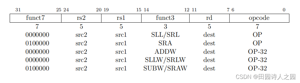
2.3 Load and Store Instructions
RV64I extends the address space to 64 bits. The execution environment will define what portions of the address space are legal to access.
RV64I extends the address space to 64 bits. The execution environment will determine which parts of the address space are legally accessible.
The LD instruction loads a 64-bit value from memory into register rd for RV64I
.
The LW instruction loads a 32-bit value from memory and sign-extends this to 64 bits before storing it in register rd for RV64I. The LWU instruction, on the other hand, zero-extends the 32-bit value from memory for RV64I. LH and LHU are defined analogously for 16-bit values, as are LB and LBU for 8-bit values. The SD, SW, SH, and SB instructions store 64-bit, 32-bit, 16-bit, and 8-bit values from the low bits of register rs2 to memory respectively.
The LW instruction loads a 32-bit value from memory, sign-extends it to 64 bits, and stores it into register rd of the RV64I. The LWU instruction zero-extends a 32-bit value in memory to RV64I. For 16-bit values, LH and LHU are similarly defined; for 8-bit values, LB and LBU are similarly defined. The SD, SW, SH and SB instructions store the 64-bit, 32-bit, 16-bit and 8-bit values of the lower bits of register rs2 into the memory respectively.
2.4 HINT Instructions
All instructions that are microarchitectural HINTs in RV32I (see Section 2.9) are also HINTs in RV64I. The additional computational instructions in RV64I expand both the standard and custom HINT encoding spaces. All instructions that are microarchitectural HINTs in RV32I (see Section 2.9) 9
knots ) also belongs to HINT in RV64I. Additional compute instructions in RV64I expand the standard and custom HINT encoding space.
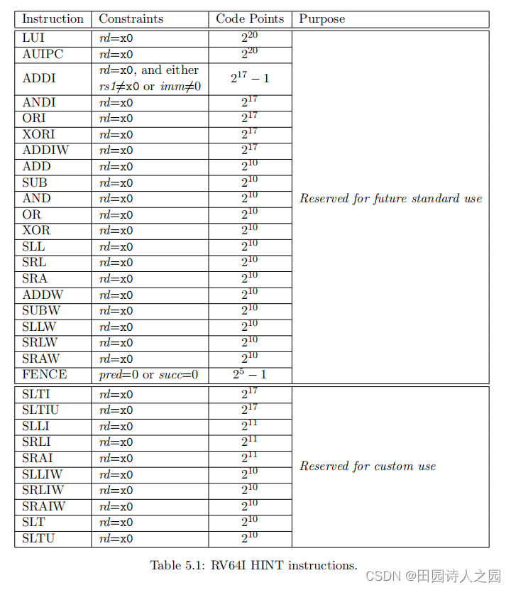
Table 5.1 lists all RV64I HINT code points. 91% of the HINT space is reserved for standard HINTs, but none are presently defined. The remainder of the HINT space is reserved for custom HINTs: no standard HINTs will ever be defined in this subspace.
Table 5.1 lists all RV64I HINT code points. 91% of the HINT space is reserved for standard HINTs, but no standard HINTs are currently defined. The rest of the HINT space is reserved for custom HINTs: this subspace will not define any standard HINTs.
reference documents
《The RISC-V Instruction Set Manual Volume I: Unprivileged ISA》