The structure used for receiving is as follows: CAN concept:
The full name is Controller Area Network, which is a half-duplex , asynchronous communication.
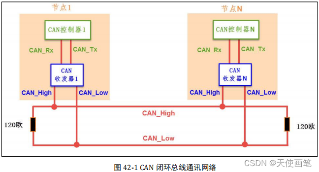
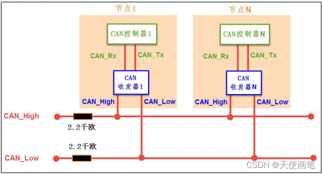
physical layer:
Closed loop: The maximum length of the bus is 40m and the maximum speed is 1Mbps. It is stipulated that there is a 120Ω resistor at both ends of the bus, and the closed loop
Open loop: The maximum transmission distance is 1Km, the maximum speed is 125Kbps, and each line is required to be connected in series with a 2.2kΩ resistor, open loop
Basic features of CAN protocol
The basic features are as follows:
Multi-master control: When the CAN bus is idle, all terminals on the bus can send messages, and the priority is determined according to the identifier (CAN ID). When there are more than two terminals on the bus to send messages, each message Each bit of the CAN ID is compared arbitrated one by one. The lower the CAN ID value, the higher the priority of the message Faster speed and longer distance: the CAN protocol can reach 1Mbps at the fastest (distance less than 40m), and the farthest can reach 10KM (rate less than 5Kbps) CAN frame types: CAN communication includes
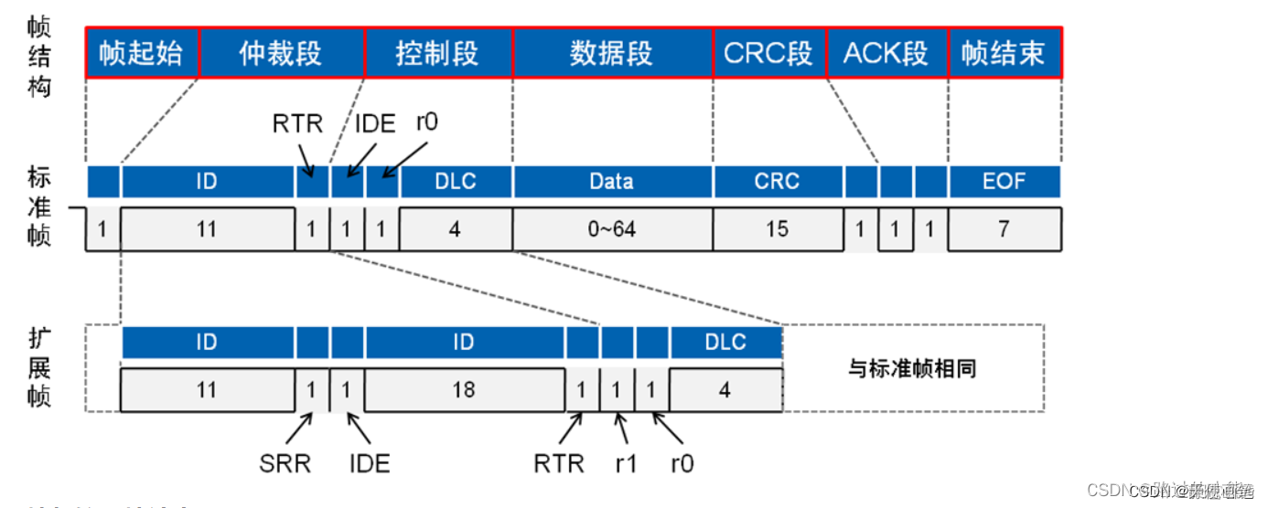
five Frame types, data frame, remote control frame, error frame, overload frame, interval frame. The most important of these is the data frame, which is used by the communication node to transmit data to the outside. There are data segments in the data frame, which are used to carry the content of the data. One frame can send 0~8 bytes of data, and the MSB comes first.
A simple understanding of the above basic features can quickly get started with the configuration of the CAN bus.
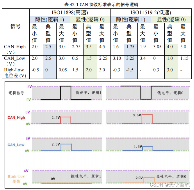
The dominant level corresponds to "0", and the recessive level corresponds to "1". The recessive level (1) the voltage of both lines is 2.5V, that is, the voltage difference is 0; the dominant level (0) CAN_High and CAN_Low are 3.5V and 1.5V respectively, and the voltage difference is 2V.
On the bus, as long as there is one node outputting dominant, the bus is at the dominant level; only when all the nodes are at the recessive level, the bus is at the recessive level
CAN network consists of CAN controller and CAN transceiver, STM32 only integrates CAN controller.
1. Hardware-chip use: STM32F103Cx series

cubeMX configuration clock
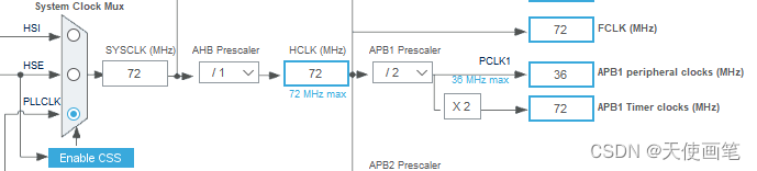
The can peripheral is mounted on APB1.

The general communication will open the receive interrupt, here open the interrupt of CAN1 RX0, the priority can be changed through NVIC .

CAN baud rate and bit synchronization
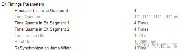
Bit Timing Breakdown

Prescaler: prescaler , to determine the CAN minimum time unit Tq.
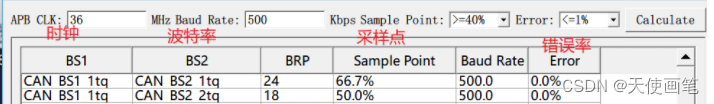
Here take F103C8T6 as an example, the APB1 clock is 36Mhz,
the method of calculating the baud rate: 36M/frequency division factor/(BS1 + BS2 + 1) is
set as shown in the figure, the baud rate is 1000Kbps, 36M / 4 / (4 + 4 + 1 ) =1M = 1000K
Baud rate calculation formula: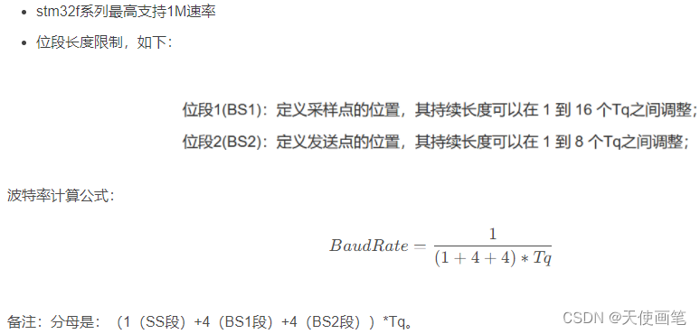
Configure working mode:
 CAN data frame format
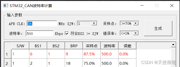
CAN baud rate calculation tool
STM32 CAN Baud Rate CalculatorV1.0-STM32 CAN Baud Rate Calculator Official Download_3DM Software
STM32 CAN communication baud rate calculator
CANPro protocol analysis platform software is the standard software of CANalyst-II+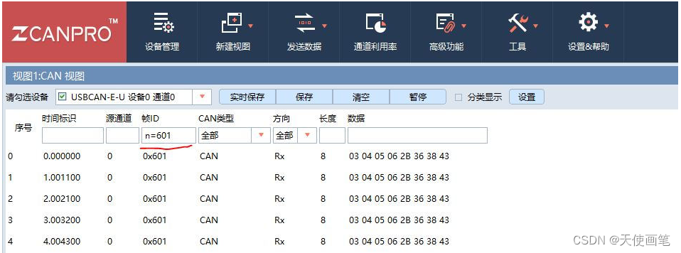

CAN Basic Function
Function Function
HAL_CAN_Start Open CAN communication
HAL_CAN_Stop Close CAN communication
HAL_CAN_RequestSleep Make the CAN module complete the current operation and try to enter sleep mode
HAL_CAN_WakeUp Wake up from sleep mode
HAL_CAN_IsSleepActive Check whether it is in sleep mode successfully
HAL_CAN_AddTxMessage Add a message to the Tx mailbox and activate the corresponding HAL_CAN_AbortTxRequest Request
to interrupt transmission
HAL_CAN_GetTxMailboxesFreeLevel Query the number of idle sending mailboxes
HAL_CAN_IsTxMessagePending Check whether there is a transmission request waiting on the specified Tx mailbox
HAL_CAN_GetRxMessage Receive a CAN frame from Rx FIFO
HAL_CAN_GetRxFifoFillLevel Query the number of unread mailboxes in the receiving mailbox
STM32HAL library learning - CAN notes_hal library can_jdhfusk's blog-CSDN blog
The structure used for sending is as follows:
typedef struct
{ uint32_t StdId; //Standard ID uint32_t ExtId; //Extended ID uint32_t IDE; //Used to determine whether the message uses standard ID or extended ID uint32_t RTR; //Used to determine whether the message is a data frame or a remote control Frame uint32_t DLC; //Data length, the value is 0-8 FunctionalState TransmitGlobalTime; //The last one is for the time trigger mode, and the time stamp will be automatically added to the last two bytes of data after it is turned on. Currently not used, select DISABLE } CAN_TxHeaderTypeDef;StdId: If the message to be sent uses a standard ID, then this member will record the value of the standard ID Value
: 0x0 ~ 0x7FFExtId: If the message to be sent uses an extended ID, then this member will record the value of the extended ID.
Value: 0x0 ~ 0x1FFFFFFFIDE: Used to determine whether the message uses a standard ID or an extended ID
value: CAN_ID_STD or CAN_ID_EXTRTR: Used to determine whether the message is a data frame or a remote frame
Value: CAN_RTR_DATA or CAN_RTR_REMOTEDLC: used to record the data length of the data frame, unit byte (if the remote control frame is to be sent, the content in this member will not work)
value: 0 ~ 8TransmitGlobalTime: Not used at present, choose
the value of DISABLE: ENABLE or DISABLE
The function used for sending is as follows:
HAL_StatusTypeDef HAL_CAN_AddTxMessage(CAN_HandleTypeDef *hcan, CAN_TxHeaderTypeDef *pHeader, uint8_t aData[], uint32_t *pTxMailbox);
CAN_TxHeaderTypeDef can_Tx;
uint8_t sendBuf[5] = {"hello"};
uint32_t box;

int main(void)
{
  	HAL_Init();
 	SystemClock_Config();
  	MX_GPIO_Init();
  	MX_CAN_Init();

    HAL_CAN_Start(&hcan1);

    can_Tx.StdId = 0x123;
    can_Tx.ExtId = 0;
    can_Tx.IDE = CAN_ID_STD;
    can_Tx.RTR = CAN_RTR_DATA;
    can_Tx.DLC = 5;
    can_Tx.TransmitGlobalTime = DISABLE;

  	while (1)
  	{
      	HAL_CAN_AddTxMessage(&hcan1, &can_Tx, sendBuf, &box);
      	HAL_Delay(100);
  	}
}
Effect: send a message every 100ms

filter
typedef struct
{ uint32_t FilterIdHigh; //High 16-bit uint32_t FilterIdLow of CAN_FiR1 register; //Low 16-bit uint32_t FilterMaskIdHigh of CAN_FiR1 register; //High 16-bit uint32_t FilterMaskIdLow of CAN_FiR2 register ; //Low 16-bit uint32_t Fil of CAN_FiR2 register terFIFOAssignment; //The message passing the filter exists in FIFO0 or uint32_t FilterBank in FIFO1; //Which filter is used in this configuration. Use a single CAN value of 0-13 uint32_t FilterMode; //mask mode or list mode uint32_t FilterScale; //32-bit or 16-bit uint32_t FilterActivation; //enable or disable uint32_t SlaveStartFilterBank; //CAN1 and CAN2 together When using, assign the number of filters to CAN2 } CAN_FilterTypeDef;member:
FilterIdHigh: The upper 16 bits of the CAN_FiR1 register are used to fill in the filter code. The specific format should be determined according to 16-bit, 32-bit; mask mode, list mode.
Value: 0x0 ~ 0xFFFFFilterIdLow: The lower 16 bits of the CAN_FiR1 register
FilterMaskIdHigh: the upper 16 bits of the CAN_FiR2 register
FilterMaskIdLow: the lower 16 bits of the CAN_FiR2 register
FilterFIFOAssignment: Messages passing the filter are stored in FIFO0 or FIFO1
Value: CAN_FILTER_FIFO0 or CAN_FILTER_FIFO1FilterBank: The filter number configured this time
Value: 0 ~ 13 for single CAN; 0 ~ 27 for dual CANFilterMode : filter mode, mask mode or list mode.
Value: CAN_FILTERMODE_IDMASK or CAN_FILTERMODE_IDMASKFilterScale: filter code size, 16 or 32 bits.
Value: CAN_FILTERSCALE_16BIT or CAN_FILTERSCALE_32BITFilterActivation : Enable or disable this filter.
Value: CAN_FILTER_DISABLE or CAN_FILTER_ENABLESlaveStartFilterBank: The number of filters allocated from CAN (CAN2). If only a single CAN is used, this member can be ignored
Value: 0 ~ 27
Fill in the filter structure, and then call the following function to take effect:
HAL_StatusTypeDef HAL_CAN_ConfigFilter(CAN_HandleTypeDef *hcan, CAN_FilterTypeDef *sFilterConfig);
CAN_FilterTypeDef can_Filter = {0};

can_Filter.FilterIdHigh = 0;
can_Filter.FilterIdLow = 0;
can_Filter.FilterMaskIdHigh = 0;
can_Filter.FilterMaskIdLow = 0;
can_Filter.FilterFIFOAssignment = CAN_FILTER_FIFO0;
can_Filter.FilterBank = 0;
can_Filter.FilterMode = CAN_FILTERMODE_IDMASK;
can_Filter.FilterScale = CAN_FILTERSCALE_32BIT;
can_Filter.FilterActivation = CAN_FILTER_ENABLE;

HAL_CAN_ConfigFilter(&hcan1, &can_Filter);
Effect: All messages on the CAN bus will be received and stored in FIFO0.
CAN_FilterTypeDef can_Filter = {0};

can_Filter.FilterIdHigh = 0;
can_Filter.FilterIdLow = 0;
can_Filter.FilterMaskIdHigh = 0;
can_Filter.FilterMaskIdLow = 2;
can_Filter.FilterFIFOAssignment = CAN_FILTER_FIFO0;
can_Filter.FilterBank = 0;
can_Filter.FilterMode = CAN_FILTERMODE_IDLIST;
can_Filter.FilterScale = CAN_FILTERSCALE_32BIT;
can_Filter.FilterActivation = CAN_FILTER_ENABLE;

HAL_CAN_ConfigFilter(&hcan1, &can_Filter);
Effect: Only receive data frame and remote control frame whose standard ID is 0x0, and store it in FIFO0.
take over
CAN reception is usually achieved by using an interrupt (because there is no DMA, and the query method is difficult to guarantee real-time performance), so the global interrupt for reception must first be enabled in CubeMX.
You can see that there are two interrupts, one is the RX0 interrupt for FIFO0 receiving data, and the other is the RX1 interrupt for FIFO1 receiving data. Only FIFO0 is used here, so only check this. (Here I also talk about my own understanding. Since one FIFO can only save 3 messages, two FIFOs can save 6 messages. We can put messages with different IDs into different FIFOs through filters , For example, we can let FIFO0 receive key and important messages, use FIFO1 to receive less important messages, and these two interrupts are independent, we can even configure them with different interrupt priorities.)
It is not enough to turn on the global interrupt, we also need to turn on the CAN FIFO message to suspend the interrupt request (that is, the interrupt enable bit of the CAN peripheral).
HAL_CAN_ActivateNotification(&hcan1, CAN_IT_RX_FIFO0_MSG_PENDING);
In this way, when CAN receives a message that meets the filter, the interrupt will be triggered, and we can receive and process the received message in this interrupt callback function. (Because the interrupt functions used by FIFO0 and FIFO1 are independent, the callback functions here are also different. You should check whether it is FIFO0 or 1.)
void HAL_CAN_RxFifo0MsgPendingCallback(CAN_HandleTypeDef *hcan)
{
    HAL_CAN_GetRxMessage(&hcan1, CAN_RX_FIFO0, &can_Rx, recvBuf);

	/*下面是你用来处理收到数据的代码,
	可以通过串口把内容发送出来,
	也可以用来控制某些外设*/
}
The structure used for receiving is as follows:
typedef struct
{
  uint32_t StdId;
  uint32_t ExtId;
  uint32_t IDE;
  uint32_t RTR;
  uint32_t DLC;
  uint32_t Timestamp;
  uint32_t FilterMatchIndex;
} CAN_RxHeaderTypeDef;
It is very similar to the sending structure, but this structure does not require us to assign a value, but is used as an output parameter of the receiving function. Only the members that the sending structure does not have are introduced here:
Timestamp: It is only useful if the time trigger mode is enabled, record the time stampFilterMatchIndex: Which filter this message is received through
The functions used to receive are as follows:
HAL_StatusTypeDef HAL_CAN_GetRxMessage(CAN_HandleTypeDef *hcan, uint32_t RxFifo, CAN_RxHeaderTypeDef *pHeader, uint8_t aData[]);
parameter:
*hcan: the handle of can, which is automatically defined by CubeMX for usRxFifo: Receive FIFO number. Parameters:CAN_RX_FIFO0orCAN_RX_FIFO1pHeader: Receive structure, here as an output parameteraData[]: Receive an array, here as an output parameter
Example:
#include <stdio.h>
CAN_RxHeaderTypeDef can_Rx;
uint8_t recvBuf[8];
uint8_t uartBuf[64];
int main(void)
{
HAL_Init();
SystemClock_Config();
MX_GPIO_Init();
MX_CAN_Init();
MX_USART1_UART_Init()
CAN_FilterTypeDef can_Filter = {0};
can_Filter.FilterIdHigh = 0;
can_Filter.FilterIdLow = 0;
can_Filter.FilterMaskIdHigh = 0;
can_Filter.FilterMaskIdLow = 0;
can_Filter.FilterFIFOAssignment = CAN_FILTER_FIFO0;
can_Filter.FilterBank = 0;
can_Filter.FilterMode = CAN_FILTERMODE_IDMASK;
can_Filter.FilterScale = CAN_FILTERSCALE_32BIT;
can_Filter.FilterActivation = CAN_FILTER_ENABLE;
HAL_CAN_ConfigFilter(&hcan1, &can_Filter);
HAL_CAN_ActivateNotification(&hcan1, CAN_IT_RX_FIFO0_MSG_PENDING);
HAL_CAN_Start(&hcan1);
while (1)
{
}
}
void HAL_CAN_RxFifo0MsgPendingCallback(CAN_HandleTypeDef *hcan)
{
uint16_t len = 0;
HAL_CAN_GetRxMessage(&hcan1, CAN_RX_FIFO0, &can_Rx, recvBuf);
if(can_Rx.IDE == CAN_ID_STD)
{
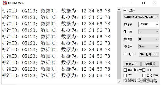
len += sprintf((char *)&uartBuf[len], "标准ID:%#X; ", can_Rx.StdId);
}
else if(can_Rx.IDE == CAN_ID_EXT)
{
len += sprintf((char *)&uartBuf[len], "扩展ID:%#X; ", can_Rx.ExtId);
}
if(can_Rx.RTR == CAN_RTR_DATA)
{
len += sprintf((char *)&uartBuf[len], "数据帧; 数据为:");
for(int i = 0; i < can_Rx.DLC; i ++)
{
len += sprintf((char *)&uartBuf[len], "%X ", recvBuf[i]);
}
len += sprintf((char *)&uartBuf[len], "\r\n");
HAL_UART_Transmit(&huart1, uartBuf, len, 100);
}
else if(can_Rx.RTR == CAN_RTR_REMOTE)
{
len += sprintf((char *)&uartBuf[len], "遥控帧\r\n");
HAL_UART_Transmit(&huart1, uartBuf, len, 100);
}
}
Effect: Receive all data on the CAN bus and print out the content through the serial port
Detailed explanation of STM32 CAN initialization
CAN is the abbreviation of Controller Area Network (CAN). It was developed by German BOSCH company, which is famous for R&D and production of automotive electronic products, and finally became an international standard (ISO11898). It is one of the most widely used field buses in the world. In North America and Western Europe, the CAN bus protocol has become the standard bus for automotive computer control systems and embedded industrial control LANs, and has a J1939 protocol designed for large trucks and heavy machinery vehicles with CAN as the underlying protocol. In recent years, its high reliability and good error detection ability have been valued, and it is widely used in automotive computer control systems and industrial environments with harsh ambient temperatures, strong electromagnetic radiation, and large vibrations.
Original link: https://blog.csdn.net/qq_20017379/article/details/125902421
u8 CAN1_Mode_Init(u8 tsjw, u8 tbs2,u8 tbs1, u16 brp, u8 mode)
{
/* gpio结构体 */
GPIO_InitTypeDef GPIO_InitStructure;
/* can 初始化结构体 */
CAN_InitTypeDef CAN_InitStructure;
/* can过滤器结构体 */
CAN_FilterInitTypeDef CAN_FilterInitStructure;
/* 使能时钟 */
RCC_AHB1PeriphClockCmd(RCC_AHB1Periph_GPIOA, ENABLE);
RCC_APB1PeriphClockCmd(RCC_APB1Periph_CAN1, ENABLE);
/* 初始化gpio
设置引脚
复用模式
推挽
速率100
上拉
*/
GPIO_InitStructure.GPIO_Pin = GPIO_Pin_11| GPIO_Pin_12;
GPIO_InitStructure.GPIO_Mode = GPIO_Mode_AF;
GPIO_InitStructure.GPIO_OType = GPIO_OType_PP;
GPIO_InitStructure.GPIO_Speed = GPIO_Speed_100MHz;
GPIO_InitStructure.GPIO_PuPd = GPIO_PuPd_UP;
GPIO_Init(GPIOA, &GPIO_InitStructure);
/* 复用pa11 pa12为can功能 */
GPIO_PinAFConfig(GPIOA, GPIO_PinSource11, GPIO_AF_CAN1);
GPIO_PinAFConfig(GPIOA, GPIO_PinSource12, GPIO_AF_CAN1);
/* 初始化can结构体 */
/*事件触发消息传输机制
在TTCAN模式下,CAN硬件的内部定时器被激活,并且被用于产生发送与接收邮箱的)时间戳
为了使can满足,适合实时性和可靠性要求特别高或有安全性要求的场合
路上各节点取得同步后, 消息只能根据调度表在规定的时间隙传输, 避免了消息传输的冲突、仲裁,消息传
输时延短, 且可预知
*/
CAN_InitStructure.CAN_TTCM=DISABLE;
/* 软件自动离线管理
ENABLE:一旦硬件检测到128 次11位连续的隐性位,则自动退出离线状态
将ABOM设1后,一旦检测到条件会自动恢复的,不需要人工干预
如果ABOM位为’1’,bxCAN进入离线状态后,就自动开启恢复过程。
如果ABOM位为’0’,软件必须先请求bxCAN进入然后再退出初始化模式,随后恢复过程才被开启
*/
CAN_InitStructure.CAN_ABOM=DISABLE;
/* 睡眠模式禁用
软件通过对CAN_MCR寄存器的SLEEP位置’1’,来请求进入这一模式。在该模式下,bxCAN的时钟停止了,但软件仍然可以访问邮箱寄存器。
当bxCAN处于睡眠模式,软件必须对CAN_MCR寄存器的INRQ位置’1’并且同时对SLEEP位清’0’,才能进入初始化模式。
有2种方式可以唤醒(退出睡眠模式)bxCAN:通过软件对SLEEP位清’1’,或硬件检测到CAN总线的活动。
如果CAN_MCR寄存器的AWUM位为’1’,一旦检测到CAN总线的活动,硬件就自动对SLEEP位清’0’来唤醒bxCAN。如果CAN_MCR寄存器的AWUM位为’0’,软件必须在唤醒中断里对SLEEP位清’0’才能退出睡眠状态。
注: 如果唤醒中断被允许(CAN_IER寄存器的WKUIE位为’1’),那么一旦检测到CAN总线活动就会产生唤醒中断,而不管硬件是否会自动唤醒bxCAN。
在对SLEEP位清’0’后,睡眠模式的退出必须与CAN总线同步,当硬件对SLAK位清’0’时,就确认了睡眠模式的退出。
*/
CAN_InitStructure.CAN_AWUM=DISABLE;
/* 自动重传使能
该模式主要用于满足CAN标准中,时间触发通信选项的需求。通过对CAN_MCR寄存器的NART位置’1’,来让硬件工作在该模式。
在该模式下,发送操作只会执行一次。如果发送操作失败了,不管是由于仲裁丢失或出错,硬件都不会再自动发送该报文。
*/
CAN_InitStructure.CAN_NART=ENABLE;
/*
报文不锁定,新报文覆盖旧报文
*/
CAN_InitStructure.CAN_RFLM=DISABLE;
/* 优先级由报文标识符决定
本成员用于选择CAN报文发送优先级判定方法
用于选择CAN报文发送优先级判定方法
*/
CAN_InitStructure.CAN_TXFP=DISABLE;
/*
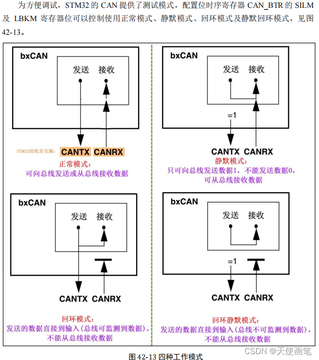
#define CAN_Mode_Normal 正常模式
#define CAN_Mode_LoopBack 回环模式 自己发,自己收
回环模式下,它自己的输出端的所有内容都直接传输到自己的输入端,输出端的内容同时也会被传输到总线上,
即也可使用总线监测它的发送内容。输入端只接收自己发送端的内容,不接收来自总线上的内容。使用回环模式可以进行自检。
#define CAN_Mode_Silent 静默模式
静默模式下,它自己的输出端的逻辑 0 数据会直接传输到它自己的输入端,逻辑1
可以被发送到总线,所以它不能向总线发送显性位(逻辑 0),只能发送隐性位(逻辑 1)。
输入端可以从总线接收内容。由于它只可发送的隐性位不会强制影响总线的状态,
所以把它称为静默模式。这种模式一般用于监测,它可以用于分析总线上的流量,但又不会因为发送显性位而影响总线
#define CAN_Mode_Silent_LoopBack 静默回环模式
回环静默模式是以上两种模式的结合,自己的输出端的所有内容都直接传输到自己的输入端,并且不会向总线发送显性位影响总线,
不能通过总线监测它的发送内容。输入端只接收自己发送端的内容,不接收来自总线上的内容。
这种方式可以在“热自检”时使用,即自我检查的时候,不会干扰总线
*/
CAN_InitStructure.CAN_Mode= mode;
/*
重新同步跳跃宽度(SJW) 。定义了在每位中可以延长或缩短多少个时间单元的上限。其值可以编程为1到4个时间单元
*/
CAN_InitStructure.CAN_SJW=tsjw;
/*
时间段1(BS1):定义采样点的位置。其值可以编程为1到16个时间单元,但也可以被自动延长,
以补偿因为网络中不同节点的频率差异所造成的相位的正向漂移。
*/
CAN_InitStructure.CAN_BS1=tbs1;
/*
时间段2(BS2):定义发送点的位置。其值可以编程为1到8个时间单元,但也可以被自动缩短以补偿相位的负向漂移。
*/
CAN_InitStructure.CAN_BS2=tbs2;
/*
分频率
*/
CAN_InitStructure.CAN_Prescaler=brp;
/* 初始化结构体 */
CAN_Init(CAN1, &CAN_InitStructure);
/* 初始化过滤器 */
/*
选择过滤器0~13 for one can register
*/
CAN_FilterInitStructure.CAN_FilterNumber = 0;
/*
屏蔽位模式和标识符列表模式
#define CAN_FilterMode_IdMask ((uint8_t)0x00)
#define CAN_FilterMode_IdList ((uint8_t)0x01)
*/
CAN_FilterInitStructure.CAN_FilterMode=CAN_FilterMode_IdMask;
/* 过滤器的位数
#define CAN_FilterScale_16bit ((uint8_t)0x00)
#define CAN_FilterScale_32bit ((uint8_t)0x01)
*/
CAN_FilterInitStructure.CAN_FilterScale=CAN_FilterScale_32bit;
/*
32位ID 高位
*/
CAN_FilterInitStructure.CAN_FilterIdHigh=0x0000;32??ID
/*
32位ID 低位
*/
CAN_FilterInitStructure.CAN_FilterIdLow=0x0000;
/* 屏蔽位高字节 */
CAN_FilterInitStructure.CAN_FilterMaskIdHigh=0x0000;
/* 屏蔽位低字节 */
CAN_FilterInitStructure.CAN_FilterMaskIdLow=0x0000;
/* 设定接收FIFO */
CAN_FilterInitStructure.CAN_FilterFIFOAssignment = CAN_Filter_FIFO0;
/* 激活过滤组 */
CAN_FilterInitStructure.CAN_FilterActivation = ENABLE;
/* 初始化过滤器 */
CAN_FilterInit(&CAN_FilterInitStructure);
/* 配置can中断*/
NVIC_InitTypeDef NVIC_InitStructure;
CAN_ITConfig(CAN1,CAN_IT_FMP0,ENABLE);
NVIC_InitStructure.NVIC_IRQChannel = CAN1_RX0_IRQn;
NVIC_InitStructure.NVIC_IRQChannelPreemptionPriority = 1;
NVIC_InitStructure.NVIC_IRQChannelSubPriority = 0;
NVIC_InitStructure.NVIC_IRQChannelCmd = ENABLE;
NVIC_Init(&NVIC_InitStructure);
return 0;
}