Introduction:
STM32CubeMX is a graphical tool that makes it very easy to configure STM32 microcontrollers and microprocessors. Therefore, the initial development process can reduce the time period. Or for beginners, you can get started with application development faster.
This series of tutorials is mainly for basic applications. The selected development tools are as follows:
1. STM32CubeMX
2. IDE: MDK-Keil
3. Development board chip: STM32F407ZET6
4. HAL library
Note: Install STM32CubeMX and Keil in advance
This section mainly explains the project creation process and LED light control
The process is as follows
1. Open the project and select the development chip
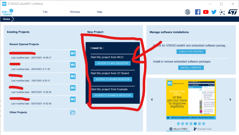
1) After opening the STM32CubeMX, you will get the interface as shown in the figure above. The old version is different, pay attention, but the related operations of the interface are similar, mainly because the layout has changed;
2) Select the "" at the arrow ACCESS TO MCU SELECTOR", which means to select the MCU model to start the configuration project; you can also choose the other two, according to your own usage, or you can try it out.
3) After clicking (2), it will enter the next step to select the specific type of chip.
2. Development chip selection
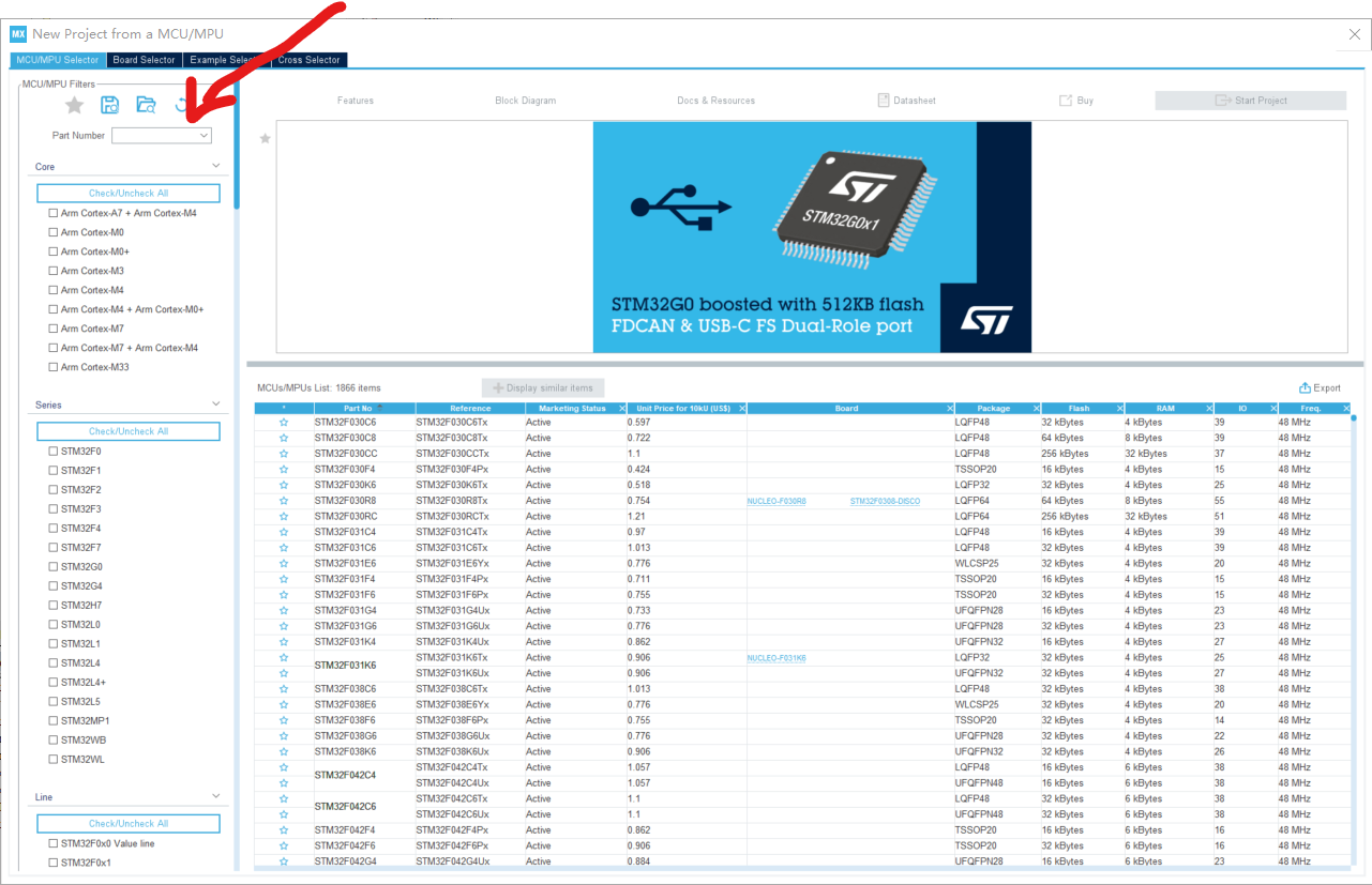
1) Output the specific chip model on the circuit board at the arrow in the above figure. The chip model used by the author is "STM32F407ZET6". When searching, enter "STM32F407" and get the following figure:
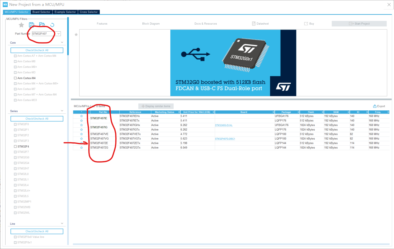
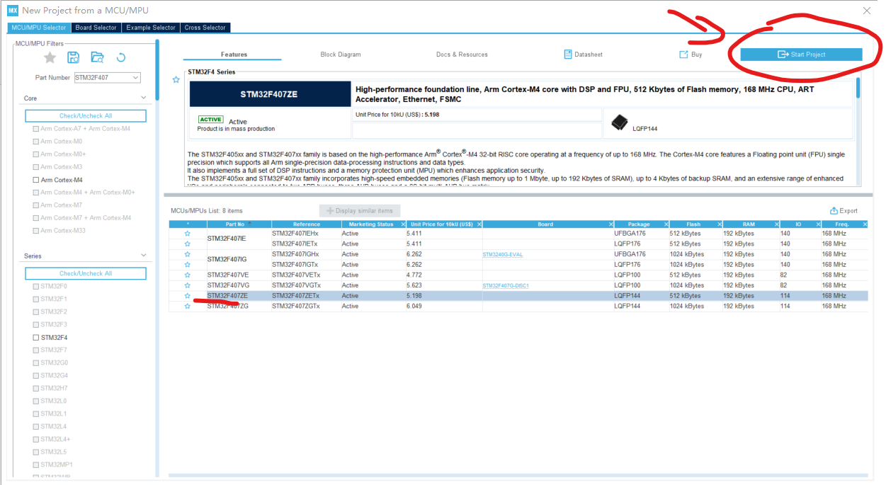
2) According to the above figure Select the specific chip for the searched model. After selection, there will be a dark color. After selection, click "Star Project" according to the following figure, and start to enter the project configuration.
3. Introduction to the project configuration interface
1) The interface after entering the configuration is shown in the figure below:
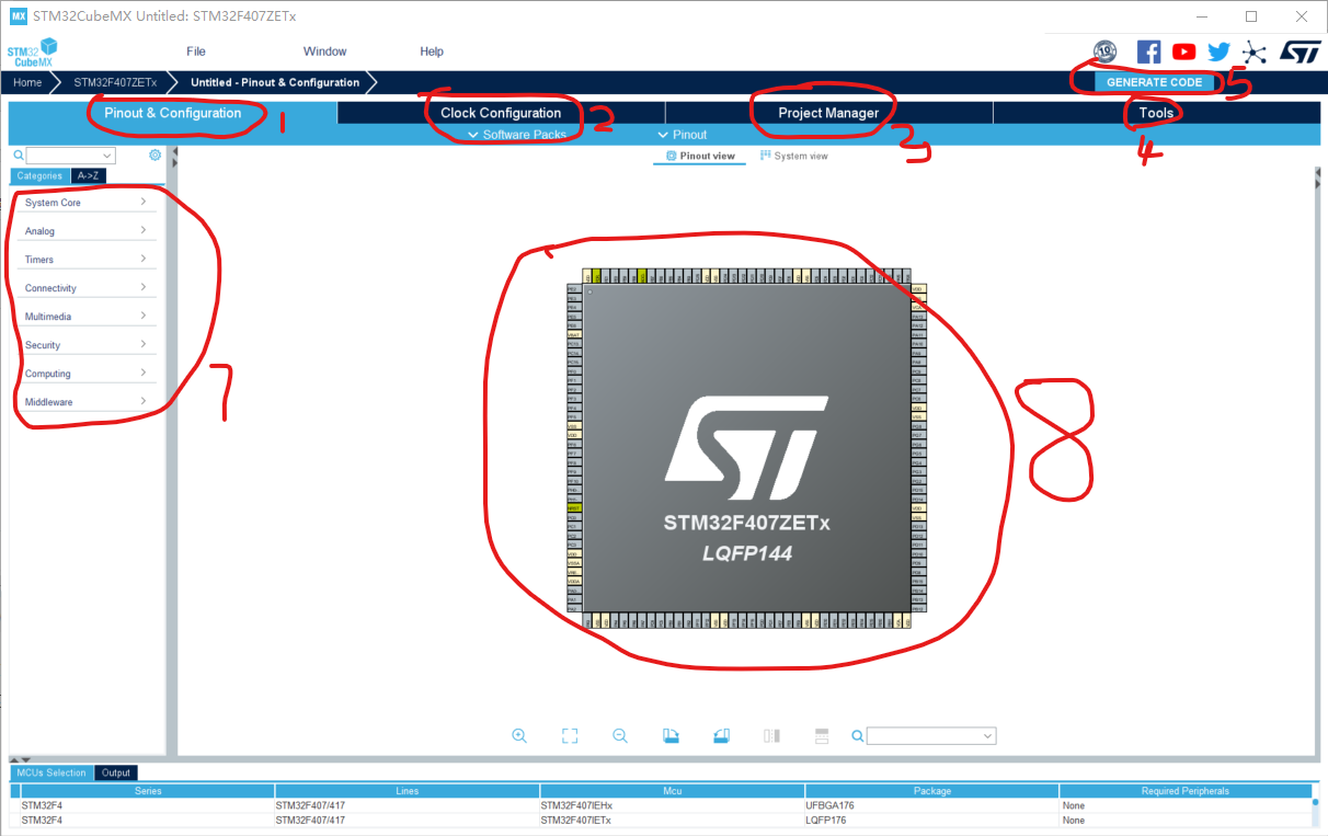
Mark 1 in the above figure: mainly for the use of the configuration chip, including: GPIO, clock source, Debug, timer, DMA, ADC, DAC, CAN, The configuration used by FSMC, I2C, SPI, SDIO, UART\USART, and other low-level drivers, as well as middle-level drivers: FATFS, FREERTOS, LIBJPEG, LWIP, etc. For detailed selection, you can check the positions of icon 7.
Mark 2 in the above figure: the clock configuration of the chip, you can see the clock of each channel and the configuration size in detail. (screenshots will follow)
Mark 3 in the above figure: some configurations of project output, including directory, project name, IDE selected, stack size configuration, etc.; (will be explained later)
Symbol 4 in the above figure: the use configuration of some development tools, which is not involved at present;
Mark 8 in the above picture: Display the chip in a graphic way, you can zoom in and out to view each pin, and configure the IO pins through the left and right mouse buttons.
Mark 5 above: After all configurations are completed, click to generate a code project, and open the project with the configured IED.
4. Engineering configuration
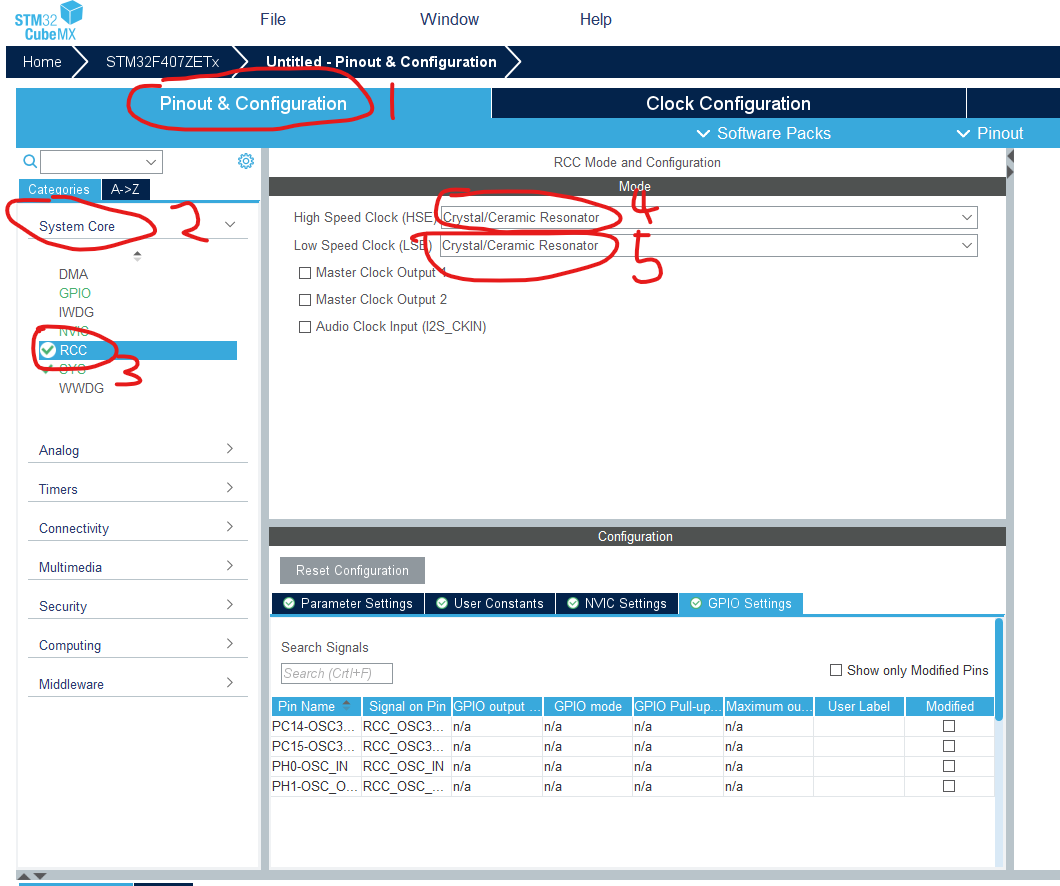
1) Configure RCC, that is, the selection configuration of the crystal oscillator;
select "Pinout&Configuration"->"System Core"->"RCC", as shown in steps 1, 2, and 3 as shown below;
High Speed Clock (HSE): Indicates external high speed Crystal oscillator;
High Speed Clock (HSE): Indicates external low-speed crystal oscillator, which is generally used when using RTC real-time clock;
in steps 4 and 5, you can choose the matching type of crystal oscillator, "BYPASS Clock Source" and "Crystal/Ceramic Resonator". The first is a bypass clock source, the second is a crystal/ceramic resonator, and the general circuit uses a "Crystal/Ceramic Resonator".
The high and low speeds chosen by the author of this tutorial are both "Crystal/Ceramic Resonator".
As shown in the figure below:
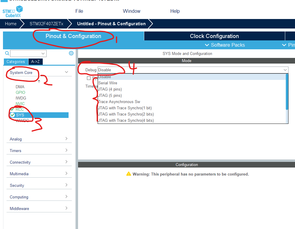
2) Configure SYS, that is, choose the way of DEBUG
Select "Pinout&Configuration"->"System Core"->"SYS", as shown in steps 1, 2, and 3 in
the following figure; Step 4 in the figure below is to select the Debug method. Generally, the SDW method can be used. If you want to use JTAG, you can also JTAG is optional.
In this tutorial, the author chose SDW as "Serial Wire".
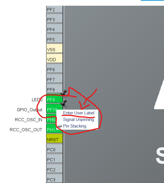
3) The development board LED0 used in the GPIO tutorial for configuring LED lights is
connected to GPIOF9, and LED1 is GPIOF10. It uses a common anode circuit, so it is active low-level lighting, as shown in the following figure:
Step 1: Select GPIOF9, click Click the left mouse button, and the option marked 3 in the figure below will appear, select GPIO_Output, that is, the output mode. Similarly, select GPIOF10;
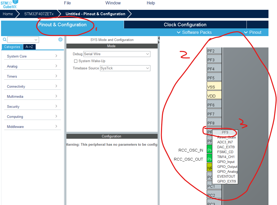
Step 2: Change the name of the pin Right-click the corresponding GPIO, pop up the option list, select "Enter User Lable", and then enter the name; here the author's GPIOF9 label name is LED0, and the label of GPIOF10 is LED1; can be filled in according to your own naming habits, and the subsequent control of it in the code is carried out through the name defined by this macro.
The above three aspects complete the function configuration for use. . . .
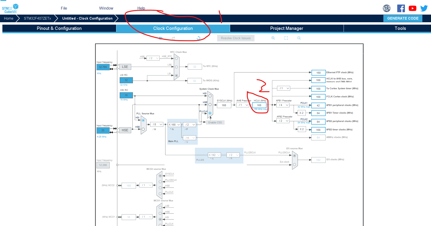
- Clock configuration
Clock configuration, click "Clock Configuration", mark the 1 position
in the following figure; mark the 2 position in the following figure, input the final frequency of the clock bus, set according to the effective range of the chip, generally the chip of F1 is 72, and the chip of F4 is 168 or 180 , Here the author chooses 180MHZ, press Enter after input, there will be a prompt, just confirm the prompt. In this way, the size configuration of the clock can be completed.
5) Output project file configuration
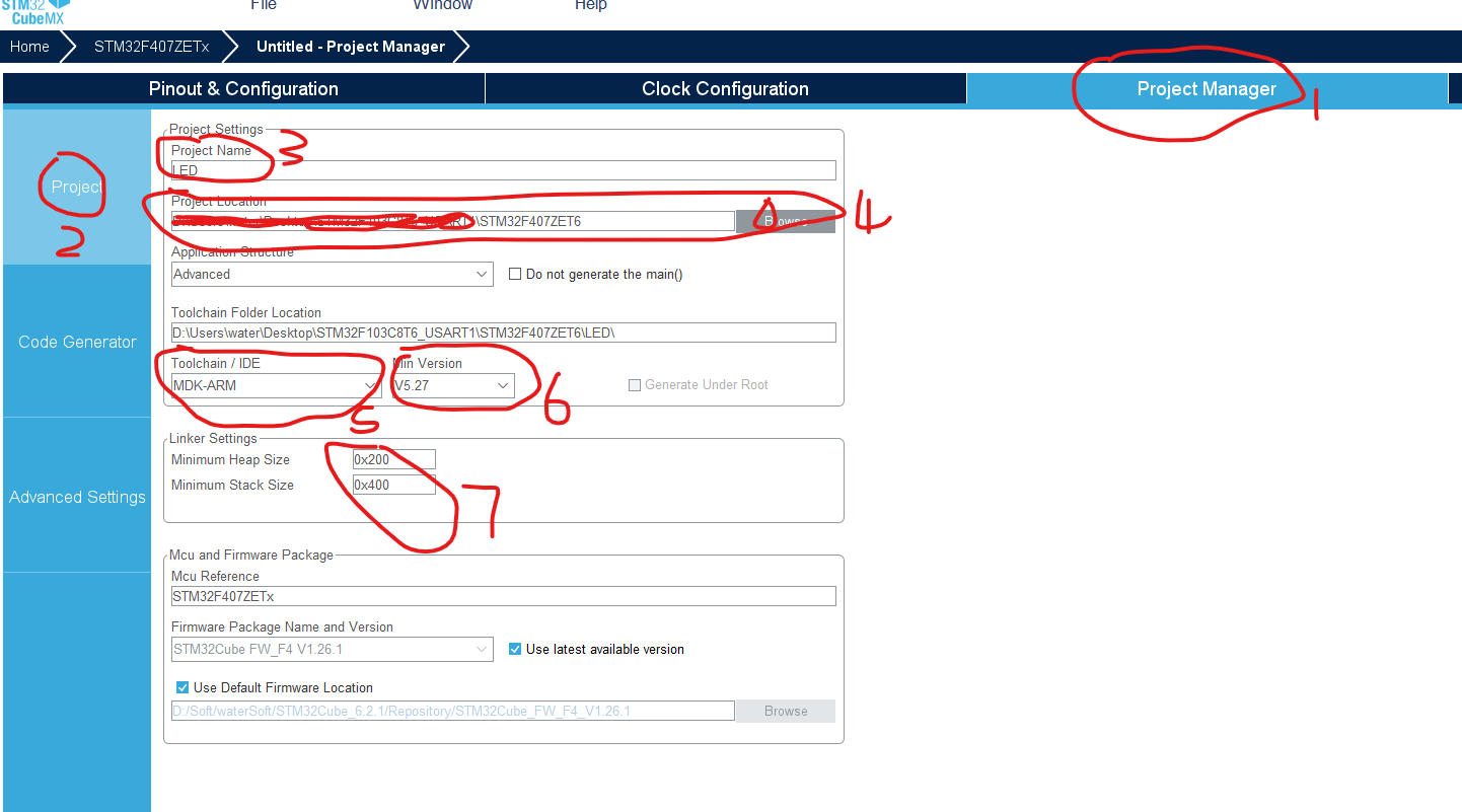
The first one: project configuration, marked as shown in the figure below,
marked 1: select "Project Manager" to enter the project configuration;
marked 2: configuration related to the project project file;
marked 3: set the name of the project, here the author uses "LED", You can write it according to your own requirements;
Note 4: The path directory where the project files are stored, do not include the Chinese path, otherwise an error may be reported. .
Note 5: IDE selection of the project, this tutorial uses keil, so MKD-ARM is selected, and you can choose the corresponding IDE according to the IDE you use.
Label 6: IDE version, the latest version is OK by default, if it is keil4, choose the lower version;
Label 7: Stack size setting, this LED project is not used very much at present, so the default size can be used, follow-up tutorials for other functions Will involve modification of the stack size.
6) Code generation configuration
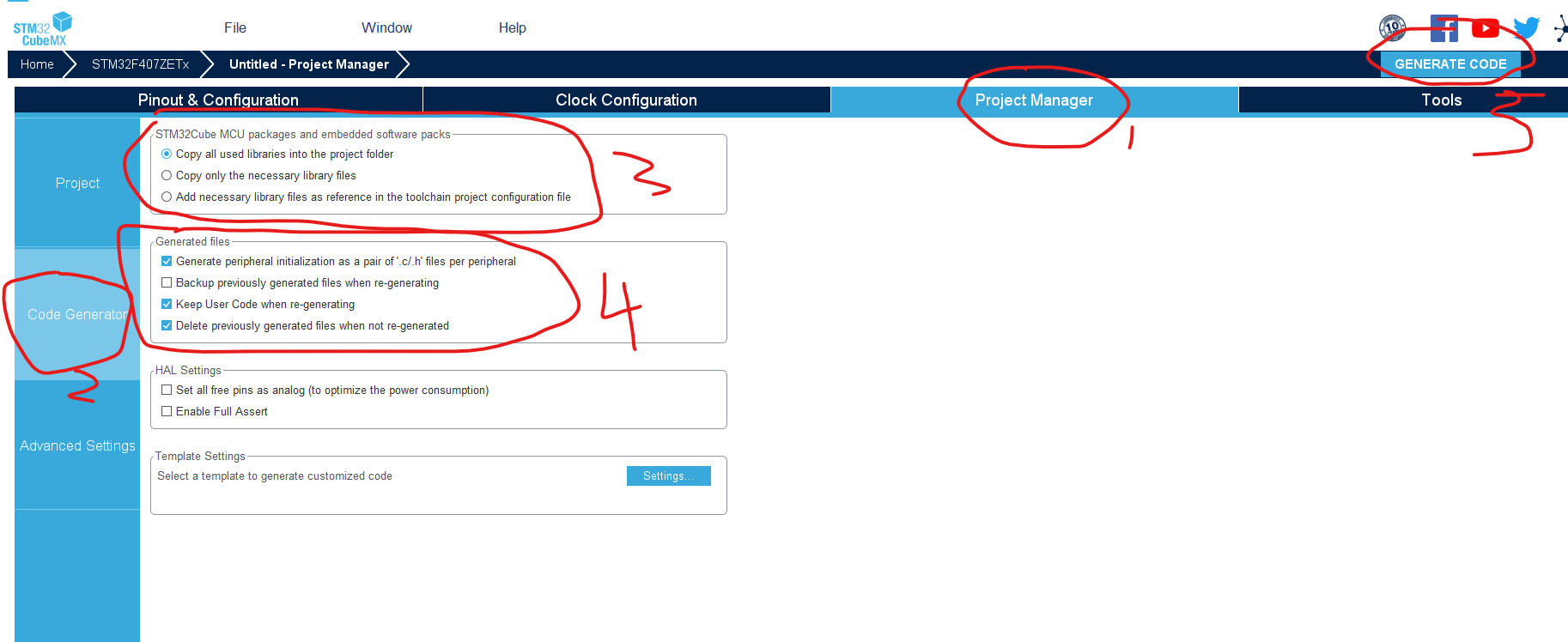
The second: code generation configuration, as marked in the figure below,
mark 1: select "Project Manager" to enter the code project configuration;
mark 2: configuration related to code generation;
mark 3: set the library file used The
first option is: copy All library files are added to the project;
the second option is: copy only the library files that need to be used;
the third option is: add the necessary library files to the toolchain project configuration file as a reference.
Here the author chooses the first , copy all library files. . .
Note 4: Configuration of generated files
First: Peripheral initialization that generates a pair of ".c/.h" files for each peripheral;
Second: Backup previously generated files when regenerating;
Third: Rebuild Keep the user code when generating;
the fourth: delete the previously generated files when not regenerating;
here the author chooses the first, the third, and the fourth;
Note 5: After all the above configurations are completed, click "GENERATE CODE" to generate a code project;
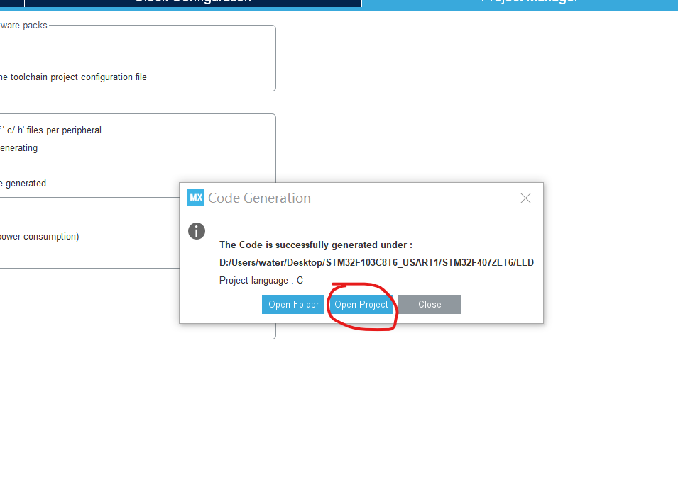
5. Code generation
Click "GENERATE CODE" to generate a code project; the prompt is as follows, click "Open Project" to open the project;
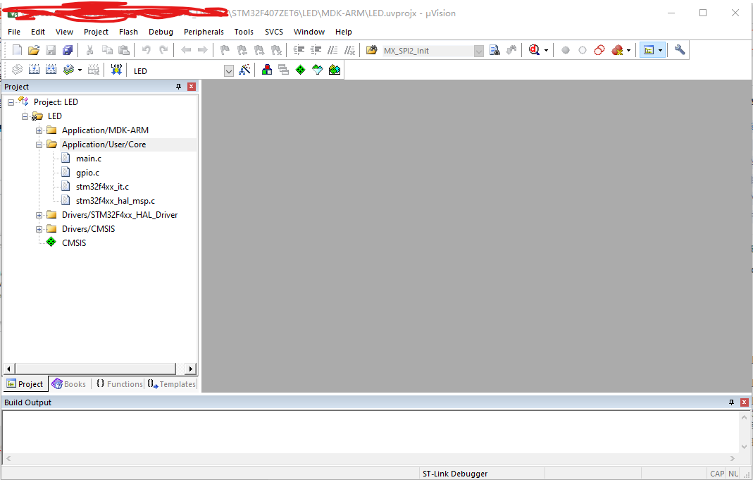
6. Add LED control code
1) Open the project as shown below:
2) Add LED control code
Step 1: After opening the project, click " 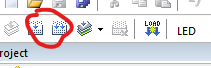 " to compile it to ensure that the relevant .h files can be found.
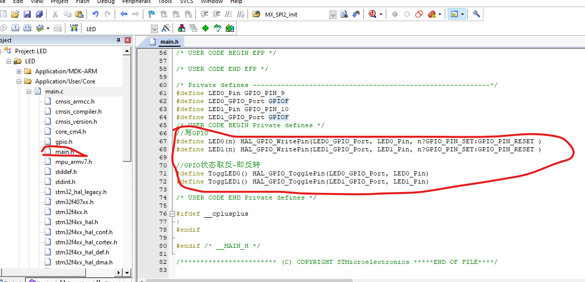
Step 2: Add the code as shown below in "main.h":
//写GPIO
#define LED0(n) HAL_GPIO_WritePin(LED0_GPIO_Port, LED0_Pin, n?GPIO_PIN_SET:GPIO_PIN_RESET )
#define LED1(n) HAL_GPIO_WritePin(LED1_GPIO_Port, LED1_Pin, n?GPIO_PIN_SET:GPIO_PIN_RESET )

//GPIO状态取反-即反转
#define ToggLED0() HAL_GPIO_TogglePin(LED0_GPIO_Port, LED0_Pin)
#define ToggLED1() HAL_GPIO_TogglePin(LED1_GPIO_Port, LED1_Pin)
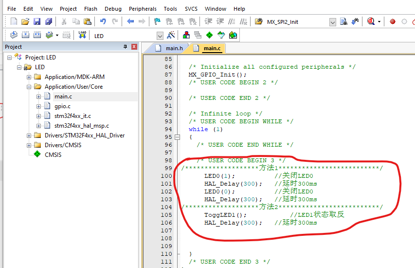
Step 3: Add control code to the main function
In the code below, method 1 is to control the flashing of LED0 by setting the state separately, and method 2 is to control the flashing of LED1 by inversion;
use one of them; here the author chooses the first one for testing.
As shown below:
/*******************方法1**************************/
	  LED0(1);			//关闭LED0
	  HAL_Delay(300);	//延时300ms
	  LED0(0);			//关闭LED0
	  HAL_Delay(300);	//延时300ms
/*******************方法2**************************/
	  ToggLED1();			//LED1状态取反
	  HAL_Delay(300);	//延时300ms
2) Compile and download
Step 1: Click “  ” to compile;
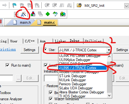
Step 2: Downloader selection, choose according to your own downloader, here the author chooses J-LINK;
Step 3: Download method configuration, please refer to the picture below for related options:

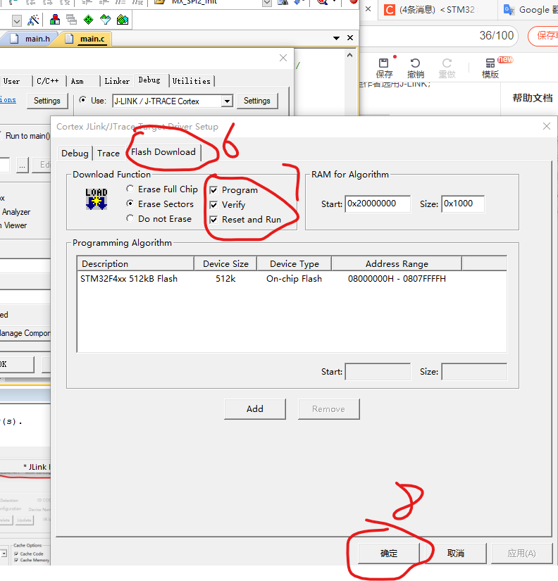
Step 4: Download
Click “  ” to download the code.
7. Effects
Since the video cannot be uploaded directly, it cannot be seen here.
The author can see LED0 flashing after downloading.
Summary: So far, the creation of the entire LED project and the control of flickering have been completed;
Welcome to communicate: QQ759521350
-------------------If there are any deficiencies in the above content, please point out and exchange ----------------
--------------------------------Reprinted to indicate the source--------------- -----------------