Table of contents
1. IP address planning and design
2. Build topology and perform basic IP configuration
3. Configure virtual local area network
1) Configure PC1 and PC2 according to subnet requirements
Detection: Enter [SW1]display vlan to check
Detection: use PC1 to access PC2
2) Configure the gateways and loopbacks of the remaining routers in the topology
1) R4 loopback cannot be declared
Interface Authentication on R4
4) Reduce routing entries configured on R3
topic
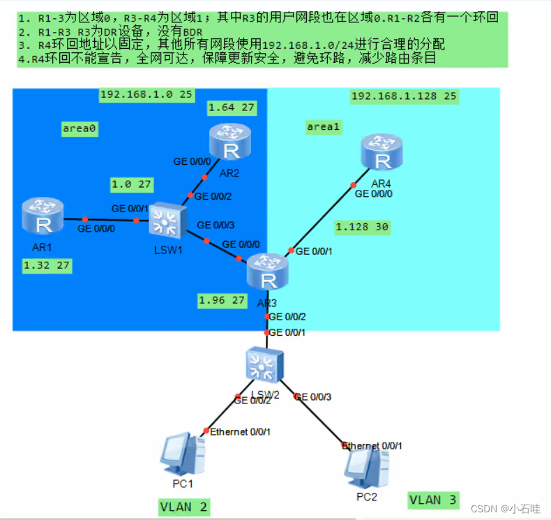
1. IP address planning and design
Zone 0: 192.168.1.0/25
1 area: 192.168.1.128/30
Among them, the 0 area needs to be divided again according to the requirements, as follows
192.168.1.0 28
192.168.1.16 28
192.168.1.32 28
192.168.1.64 28
192.168.1.80 28
192.168.1.96 28
192.168.1.109 28 reserved address
192.168.1.125 28
We take the first five and the rest as reserved addresses
Then the area 0 IP address is divided into:
0/0/0 interface of R123: 192.168.1.0/28
Loopback of R1: 192.168.1.16/28
Loopback of R2: 192.168.1.32/28
vlan2: 192.168.1.64/28
vlan3: 192.168.1.80/28
2. Build topology and perform basic IP configuration

3. Configure virtual local area network
1 ) Configure PC1 and PC2 according to subnet requirements
At the same time configure the planned gateway 192.168.1.65/28 192.168.1.81/28
Enter in the switch:
<Huawei>system-view
[Huawei]sys SW1
[SW1]vlan batch 2 3
[SW1]interface GigabitEthernet 0/0/2
[SW1-GigabitEthernet0/0/2]port link-type access
[SW1-GigabitEthernet0/0/2]port default vlan 2
[SW1-GigabitEthernet0/0/2]q
[SW1]interface GigabitEthernet 0/0/3
[SW1-GigabitEthernet0/0/3]port link-type access
[SW1-GigabitEthernet0/0/3]port default vlan 3
[SW1-GigabitEthernet0/0/3]q
Detection: Enter [SW1]display vlan to check
[SW1]interface GigabitEthernet 0/0/1
[SW1-GigabitEthernet0/0/1]port link-type trunk
[SW1-GigabitEthernet0/0/1]port trunk allow-pass vlan 2 3
Configure Router R3
<Huawei>system-view
[Huawei]sysname R3
[R3]interface GigabitEthernet 0/0/2.1
[R3-GigabitEthernet0/0/2.1]ip address 192.168.1.65 28
[R3-GigabitEthernet0/0/2.1]q
[R3]interface GigabitEthernet 0/0/2.2
[R3-GigabitEthernet0/0/2.2]ip address 192.168.1.81 28
[R3-GigabitEthernet0/0/2.2]dot1q termination vid 3
[R3-GigabitEthernet0/0/2.2]arp broadcast enable
[R3-GigabitEthernet0/0/2.2]q
[R3]interface GigabitEthernet 0/0/2.1
[R3-GigabitEthernet0/0/2.1]dot1q termination vid 2
[R3-GigabitEthernet0/0/2.1]arp broadcast enable
Detection: use PC1 to access PC2
2 ) Configure the gateways and loopbacks of the remaining routers in the topology
R1 configuration:
<Huawei>system-view
[Huawei]sysname R1
[R1]interface GigabitEthernet 0/0/0
[R1-GigabitEthernet0/0/0]ip address 192.168.1.1 28
[R1-GigabitEthernet0/0/0]q
[R1]interface LoopBack 0
[R1-LoopBack0]ip address 192.168.1.17 28
R2 configuration:
<Huawei>system-view
[Huawei]sysname R2
[R2]interface GigabitEthernet 0/0/0
[R2-GigabitEthernet0/0/0]ip address 192.168.1.2 28
[R2-GigabitEthernet0/0/0]q
[R2]interface LoopBack 0
[R2-LoopBack0]ip address 192.168.1.29 28
R3 configuration:
<R3>system-view
[R3]interface GigabitEthernet 0/0/0
[R3-GigabitEthernet0/0/0]ip address 192.168.1.3 28
[R3-GigabitEthernet0/0/0]q
[R3]interface GigabitEthernet 0/0/1
[R3-GigabitEthernet0/0/1]ip address 192.168.1.129 30
R4 configuration:
<Huawei>system-view
[Huawei]sysname R4
[R4]interface GigabitEthernet 0/0/0
[R4-GigabitEthernet0/0/0]ip address 192.168.1.130 30
[R4-GigabitEthernet0/0/0]q
[R4]interface LoopBack 0
[R4-LoopBack0]ip address 4.4.4.4 24
Detection: Enter display ip interface brief in sequence to detect
4. Configure dynamic routing
Using the OSPF protocol
1 ) Configure in sequence
R1 configuration:
[R1]ospf 1 router-id 1.1.1.1
[R1-ospf-1]area 0
[R1-ospf-1-area-0.0.0.0]network 192.168.1.16 0.0.0.15
[R1-ospf-1-area-0.0.0.0]network 192.168.1.0 0.0.0.15
R2 configuration:
[R2]ospf 1 router-id 2.2.2.2
[R2-ospf-1]area 0
[R2-ospf-1-area-0.0.0.0]network 192.168.1.32 0.0.0.15
[R2-ospf-1-area-0.0.0.0]network 192.168.1.0 0.0.0.15
R3 configuration:
[R3]ospf 1 router-id 3.3.3.3
[R3-ospf-1]a
[R3-ospf-1]area 0
[R3-ospf-1-area-0.0.0.0]network 192.168.1.0 0.0.0.15
[R3-ospf-1-area-0.0.0.0]network 192.168.1.64 0.0.0.15
[R3-ospf-1-area-0.0.0.0]q
[R3-ospf-1]area 1
[R3-ospf-1-area-0.0.0.1]network 192.168.1.129 0.0.0.0
R4 configuration:
[R4]ospf 1 router-id 4.4.4.4
[R4-ospf-1]area 1
[R4-ospf-1-area-0.0.0.1]network 192.168.1.130 0.0.0.0
2 ) Complete Requirement 2
.R1~R3 R3 is DR equipment, no BDR
R1 configuration:
[R1-GigabitEthernet0/0/0]ospf dr-priority 0
R2 configuration:
[R2-GigabitEthernet0/0/0]ospf dr-priority 0
R3 configuration:
Detection: <R3>display ospf peer
OSPF Process 1 with Router ID 3.3.3.3
Neighbors
Area 0.0.0.0 interface 192.168.1.3(GigabitEthernet0/0/0)'s neighbors
Router ID: 1.1.1.1 Address: 192.168.1.1
State: Full Mode:Nbr is Slave Priority: 0
DR : 192.168.1.3 BDR : None MTU : 0
Dead timer due in 39 sec
Retrans timer interval: 5
Neighbor is up for 00:02:15
Authentication Sequence: [ 0 ]
Router ID: 2.2.2.2 Address: 192.168.1.2
State: Full Mode:Nbr is Slave Priority: 0
DR : 192.168.1.3 BDR : None MTU : 0
Dead timer due in 32 sec
Retrans timer interval: 5
Neighbor is up for 00:01:32
Authentication Sequence: [ 0 ]
Neighbors
Area 0.0.0.1 interface 192.168.1.129(GigabitEthernet0/0/1)'s neighbors
Router ID: 4.4.4.4 Address: 192.168.1.130
State: Full Mode:Nbr is Master Priority: 1
DR: 192.168.1.130 BDR: 192.168.1.129 PERSON: 0
Dead timer due in 29 sec
Retrans timer interval: 5
Neighbor is up for 00:13:43
Authentication Sequence: [ 0 ]
5. Complete Requirement 4
R4 loopback cannot be announced, the entire network is reachable, ensuring update security, avoiding loops, and reducing routing entries
1) R4 loopback cannot be declared
Configure [R4-ospf-1] default-route-advertise always on R4
Detection: Enter <R1>display ip routing-table on R1 to check
Route Flags: R - relay, D - download to fib
------------------------------------------------------------------------------
Routing Tables: Public
Destinations : 13 Routes : 13
Destination/Mask Proto Pre Cost Flags NextHop Interface
0.0.0.0/0 O_ASE 150 1 D 192.168.1.3 GigabitEthernet
0/0/0
……………
2) Guarantee update security
certified
Regional authentication on R3
[R3-ospf-1]area 0
[R3-ospf-1-area-0.0.0.0]authentication-mode md5 1 plain 123456
[R3-ospf-1]area 1
[R3-ospf-1-area-0.0.0.1]authentication-mode md5 1 plain 123456
Interface Authentication on R4
[R4]interface GigabitEthernet0/0/0
[R4-GigabitEthernet0/0/0]ospf authentication-mode md5 1 plain 123456
Detection: Enter <R1>display ip routing-table on R1 to check
3) Avoid loops
Configure empty connection
[R3]ip route-static 0.0.0.0 0 NULL 0
4 ) Reduce routing entries
and configure on R3
[R3-ospf-1-area-0.0.0.0]abr-summary 192.168.1.0 255.255.255.224
Detection: Enter display ip routing-table protocol ospf on R4 to check.
Route Flags: R - relay, D - download to fib
------------------------------------------------------------------------------
Public routing table : OSPF
Destinations : 2 Routes : 2
OSPF routing table status : <Active>
Destinations : 2 Routes : 2
Destination/Mask Proto Pre Cost Flags NextHop Interface
192.168.1.0/27 OSPF 10 2 D 192.168.1.129 GigabitEthernet
0/0/0
192.168.1.64/28 OSPF 10 2 D 192.168.1.129 GigabitEthernet
0/0/0
OSPF routing table status : <Inactive>
Destinations : 0 Routes : 0