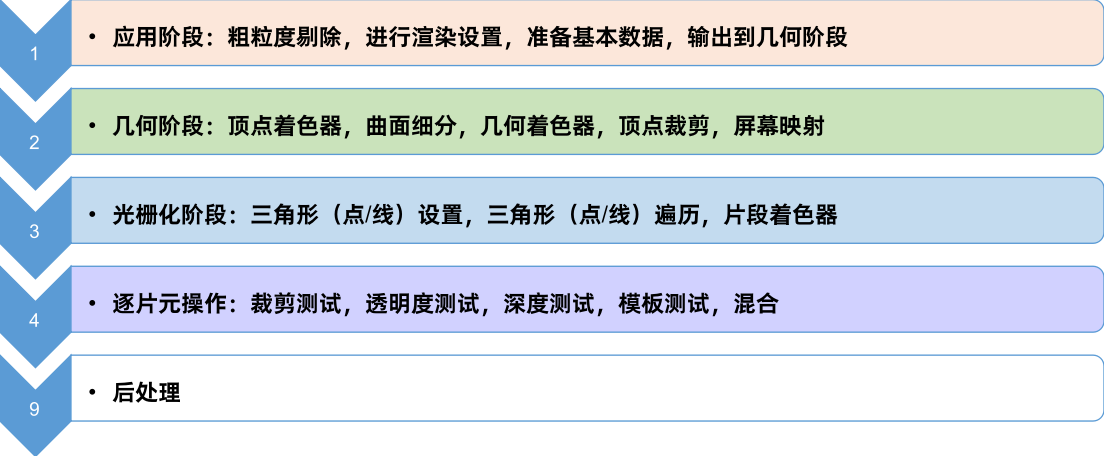
overall process

Application stage: coarse-grained culling, rendering settings, preparing basic data, output to geometry stage
Geometry Stage: Vertex Shader, Tessellation, Geometry Shader, Vertex Clipping, Screen Mapping
Rasterization stages: triangle (point/line) setup, triangle (point/line) traversal, fragment shader
Fragment-by-fragment operations: crop test, transparency test, depth test, stencil test, blending
Post-processing
CPU stage
① Application stage:
Prepare basic scene data -> accelerate algorithm, coarse-grained culling -> set rendering state, prepare rendering parameters -> call drawcall, output rendering primitives to video memory
GPU stage
②Geometry stage:
Vertex Shader -> Geometry Shader -> Tessellation Shader -> Projection -> Clipping -> Screen Mapping
③ Rasterization stage
Triangle Settings -> Triangle Traversal -> Fragment Shader
④Piece by piece operation
Clipping test, transparency test, stencil test, depth test, pixel shader, color blending, target buffer
⑤ post-processing

----------------------------- CPU stage ----------------- ----------------
application stage
Developers at this stage mainly have 3 tasks:
① Prepare the scene data, such as the position of the camera, which models are included in the frustum scene, which light sources are used, etc.;
②In order to improve rendering performance, coarse-grained culling is required to remove invisible objects, so that they do not need to be handed over to the geometry stage for processing.
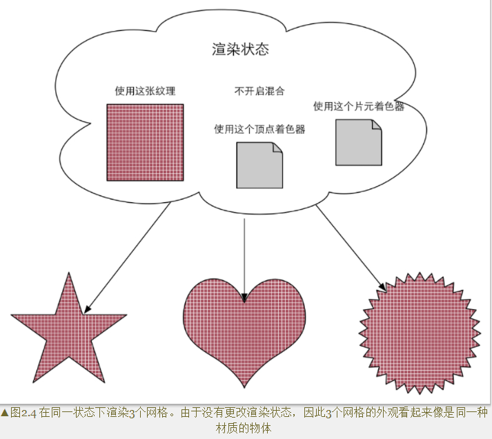
③Set the rendering state of each model. These rendering states include, but are not limited to, the materials they use (diffuse color, specular color), the textures they use, shaders, etc.
The most important output of this stage is the geometric information required for rendering, that is, rendering primitives. Simply put, it is to pass the rendering primitives (points, lines, triangles) to the next stage - the geometry stage.
The intuitive point refers to the various operations that the developer performs in the game engine, such as placing the model, camera position, assigning materials, and so on.
Prepare basic scene data -> accelerate algorithm, coarse-grained culling -> set rendering state, prepare rendering parameters -> call drawcall, output rendering primitives to video memory
---------------------------------------- For detailed steps, refer to "Introduction to Unity Shader Essentials"--- ---------------------------------
Communication between CPU and GPU
The starting point of the rendering pipeline is the CPU, the application stage. The application stage can be roughly divided into the following three stages:
(1) Load the data into the video memory
(2) Set the rendering state
(3) Call Draw Call
load data into video memory
The data required for rendering must be loaded from the hard disk (Hard Disk Drive, HHD) to the system memory (Random Access Memory, RAM). Then data such as grids and textures are loaded into the storage space of the graphics card-VRAM (Video Rnadom Access Memory, VRAM).
Hard disk (HHD) -> system memory (RAM) -> video memory (VRAM)

In addition to the texture and grid shown in the above figure, there are: vertex position information, discovery direction, fixed point color, texture coordinates, etc.
After loading data into video memory, the data in RAM can be removed. But some data still needs to access them later (for example, the CPU can access mesh data for collision detection), then there is no need to remove, because the process of loading from hard disk to RAM is very time-consuming.
set render state
As the name implies, set some rendering-related parameters. For example, which vertex shader (Vertex Shader)/fragment shader (Fragment Shader) to use, light source properties, materials, etc.
After all the above work is ready (the data is ready), the CPU can call a rendering command to tell the GPU to start rendering. This rendering command is DrawCall .
Call DrawCall
DrawCall is actually a command, its initiator is the CPU, and the receiver is the GPU. This command will only point to a list of primitives that need to be rendered, and will not contain any material information (this is because we have already done it in the previous stage)
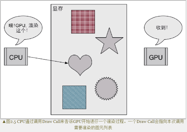
The specific rendering process in the middle is something in the GPU pipeline.
----------------------------- GPU stage ----------------- ----------------
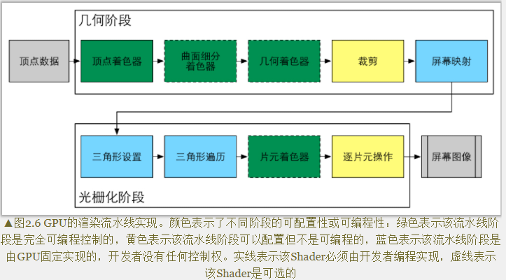
In the geometry stage and the rasterization stage, the developer cannot have absolute control, and the implementation carrier is the GPU. However, some permissions will be opened to developers for their operation.
Fully programmable control: Vertex Shader, Tessellation Shader, Geometry Shader, Fragment Shader
Configurable and non-programmable: Clipping, Per-Fragment Operations
GPU fixed implementation, developers have no control: Screen Mapping, Triangle Setup, Triangle Traversal
Vertex Shader (Vertex Shader): It is usually used to implement functions such as vertex space transformation and vertex coloring.
Tessellation Shader: It is an optional shader for subdividing primitives, such as making snow and smoothing models.
Geometry Shader: An optional shader that can be used to perform Per-Primitive shading operations, or to generate more primitives.
Clipping: The purpose of this stage is to clip the vertices that are not in the camera's field of view, and to remove the faces of some triangular primitives. For example, you can use a custom clipping plane to configure the clipping area, and you can also control the front or back of the clipped triangle primitives through commands. The CutOff function uses this step.
Screen Mapping (Screen Mapping): It is responsible for converting the coordinates of each primitive into the screen coordinate system.
Triangle Setup, Triangle Traversal: Merge vertices into triangles, and stitch triangles into pieces.
Per-Fragment Operations: Responsible for more important operations, such as modifying color, depth buffer, color mixing, etc.
geometry stage
The geometry stage is responsible for dealing with each rendering primitive, performing vertex-by-vertex and polygon-by-polygon operations. An important task in the geometry stage is to convert the vertex coordinates into the screen space, and then hand them over to the rasterizer for processing.
After multi-step processing of the input rendering primitives, this stage will output the two-dimensional vertex coordinates of the screen space, the depth value corresponding to each vertex, coloring and other related information , and pass it to the next stage.
In other words, this stage is to decide what primitives need to be drawn, how to draw them, and where to draw them.
Vertex Shader (Vertex Shader)
The input comes from the CPU. The vertex shader itself cannot create or destroy any vertices, and cannot get the relationship between vertices. For example, there is no way to know whether two vertices belong to the same triangular mesh. Because of this mutual independence, the GPU can use its own characteristics to process each vertex in parallel, which means that the processing speed of this stage will be very fast.
Main work: coordinate transformation and per-vertex lighting.
Secondary function: It can also output the data required by the subsequent stage.
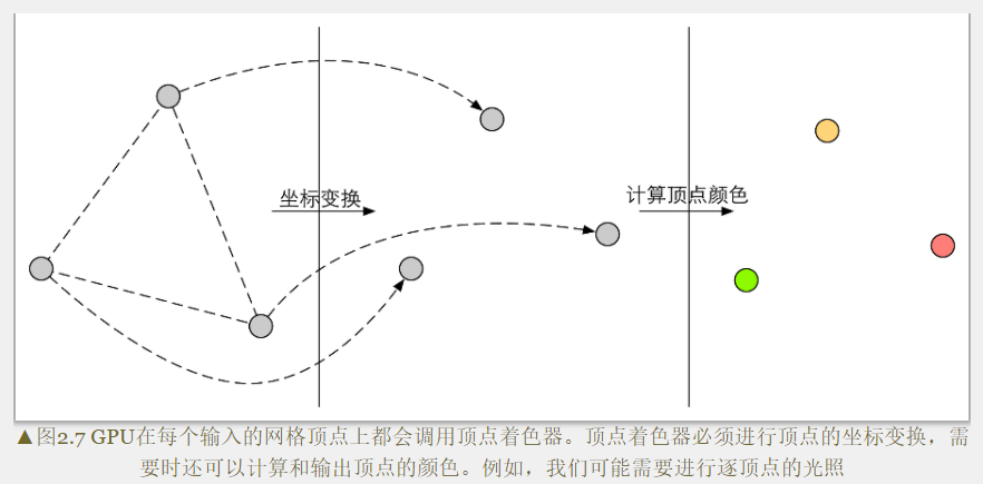
coordinate transformation
Apply some kind of transformation to the coordinates (ie positions) of the vertices. The vertex shader can change the vertex position in this step, which is very useful in vertex animation. For example, changing vertex positions to simulate horizontal planes, cloth, etc.
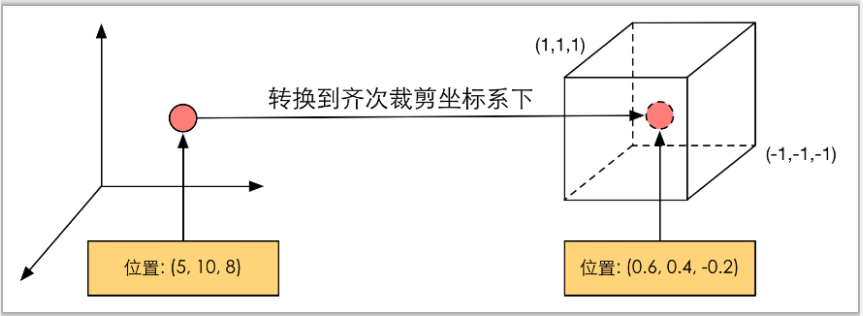
Regardless of how to change the vertex position, a basic vertex shader must complete one job: transform the vertex coordinates from the model space to the homogeneous clipping space. For example in the code
o.pos = mul(UNITY_MVP,v.position);
This code is to convert the vertex coordinates to the homogeneous clipping coordinate system, and then usually perform perspective division by the hardware, and finally get the normalized device coordinates (Normalized Device Coordinates, NDC) .
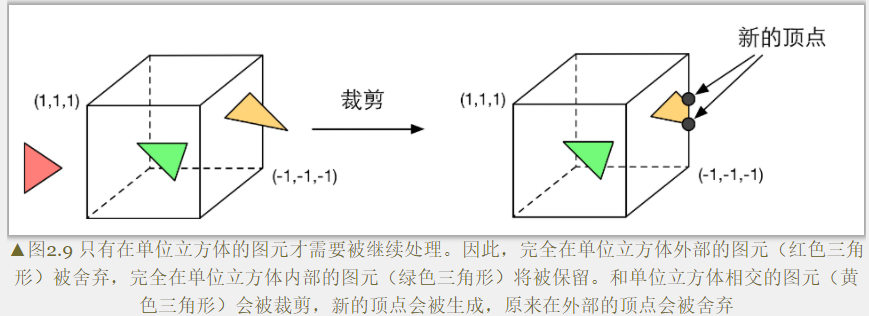
Clipping
Objects that are not in the field of view of the camera are removed.
There are three types of relationship between a primitive and the camera's field of view: completely in the field of view, partially in the field of view, and completely outside the field of view.
The primitives that are completely in the field will continue to be passed to the next pipeline stage, and the primitives that are completely out of view will not continue to be passed down. And those parts that are primitives in the industry need to be processed, which is clipping.
Screen Mapping
The coordinates of this input are still coordinates in the three-dimensional coordinate system (the range is within the unit cube).
Main task: convert the x and y axis coordinates of each graphic element to the screen coordinate system (Screen Coordinates).
The screen coordinate system is a two-dimensional coordinate system.
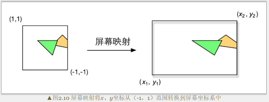
OpenGL is different from DirectX coordinate system.
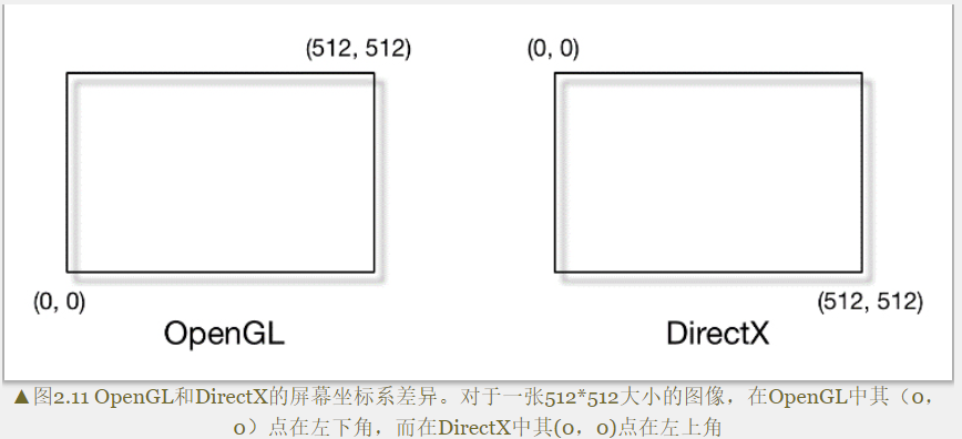
Screen mapping only converts the x and y axes, and does not do anything with the z axis. The screen coordinate system and the z coordinate form a new coordinate system called the window coordinate system (Window Coordinates).
These values are passed together to the rasterization stage.
rasterization stage
The information output in the previous stage is the position of vertices in the screen space coordinate system and additional information related to them, such as depth value (z coordinate), normal direction, viewing angle direction, etc.
Main goals: ① Calculate which pixels are covered by each primitive ② Calculate their colors for these pixels
Triangle Setup
This stage computes the information needed to rasterize a triangle mesh.
The output of the previous stage is the vertices of the triangular mesh, that is, what we get is the two endpoints of each side of the triangular mesh. If you want to get the pixel coverage of the entire triangle mesh, you need to calculate the pixel coordinates on each edge. In order to be able to calculate the coordinate information of the boundary pixels, the representation of the inverted triangle boundary is required. This process is called triangle setup.
Simply put, it is to connect individual vertices into triangular faces.
Triangle Traversal
Checks whether each pixel is covered by a triangle mesh. If overwritten, a fragment is generated . Such a process of finding those pixels covered by the triangle mesh is triangle traversal, and this stage is also called Scan Conversion (Scan Conversion).

The output of this step is to get a fragment sequence. It should be noted that a fragment is not a pixel in the true sense, but a collection of many states, which are used to calculate the final color of each pixel. These states include (but are not limited to) its screen coordinates, depth information, and vertex information output by other assembly stages, such as normals, texture coordinates, etc.
Fragment Shader
It is called a pixel shader (Pixel Shader) in DirectX, but a fragment shader is a more appropriate name, because a fragment is not a real pixel at this time.
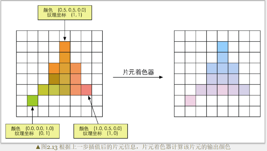
The input to the fragment shader is the result of the interpolation of the vertex information in the previous stage, specifically, the difference between the data input from the vertex shader. And its output is one or more color values.
Main task: texture sampling.
The fragment shader performs texture sampling, and usually outputs the texture coordinates corresponding to each vertex in the vertex shader stage, and then interpolates the texture coordinates corresponding to the three vertices of the triangle mesh through the rasterization stage to obtain the covering fragment texture coordinates.
While a fragment shader can perform many important effects, it is limited in that it can only affect a single fragment. That is, when a fragment shader executes, it cannot send any of its own results directly to its neighbors. There is one exception, that is, the fragment shader can access the derivative information (gradient, or derivative).
Fragment-by-Piece Operations
The last step of the rendering pipeline, PerFragment Operations is a term in OpenGL, and it is called Output-Merger in DirectX.
main mission:
① Determine the visibility of each fragment. This involves a lot of testing work, such as depth testing, stencil testing, etc.
②If a fragment passes all the tests, it is necessary to merge or mix the color value of this fragment with the color already stored in the color buffer.

Transparency tests precede stencil tests.
A fragment can only be merged with the color buffer if it passes all tests. Otherwise, it will be discarded, and all the work done to generate this fragment will be in vain.
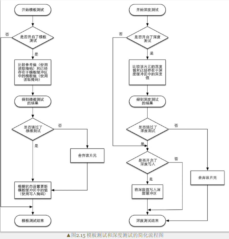
Stencil Test
Related to stencil testing is the stencil buffer. In fact, stencil buffers, color buffers, and depth buffers are almost the same thing.
If the stencil test is enabled, the GPU will first read (use the read mask) the stencil value of the fragment position in the stencil buffer, and then compare the value with the read (use the read mask) to the reference value (reference value) for comparison, this comparison function can be specified by the developer, for example, the fragment is discarded when it is less than. If the fragment fails this test, the fragment is discarded. Regardless of whether a fragment passes the stencil test or not, we can modify the stencil buffer according to the stencil test and the following depth test, and this operation is also specified by the developer. Developers can set modification operations under different results. For example, the stencil buffer remains unchanged when it fails, and the value of the corresponding position of the stencil buffer is increased by one when it passes.
Stencil testing is often used to limit the rendering area. In addition, the stencil test also has some advanced applications, such as rendering shadows, outline rendering, etc.
Depth Test
The GPU will compare the depth value of the fragment with the depth value already in the depth buffer. This comparison function can also be set by the developer, such as discarding the fragment when it is less than or discarding the fragment when it is greater than or equal to. Usually this function is less than or equal to the relationship, that is, if the depth value of this fragment is greater than or equal to the value in the current depth buffer, then it will be discarded. Because we always want to only display objects close to the camera, and those that are obscured by other objects do not need to appear on the screen.
Somewhat different from the stencil test, if a fragment fails the depth test, it has no right to change the value in the depth buffer. If it passes the test, the developer can also specify whether to overwrite the original depth value with the depth value of this fragment, which is done by turning on/off depth writing . Transparency effects are closely related to depth testing and depth writing.
Blend
Solve the problem of choosing between the color in the color buffer and the newly rendered color at each rendering.
For opaque objects, the Blend operation can be turned off. In this way, the color value calculated by the fragment shader will directly overwrite the pixel value in the color buffer.
For translucent objects, you need to enable the Blend operation.
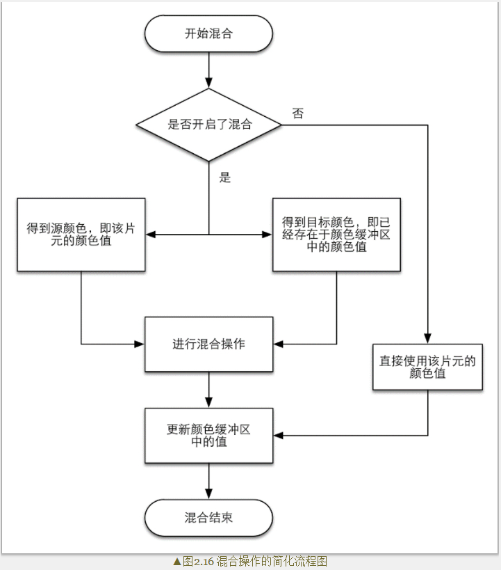
When blending is turned on, a blend function is used to perform the blending operation. This mixing function is closely related to the transparent channel, such as adding, subtracting, multiplying, etc. according to the value of the transparent channel.
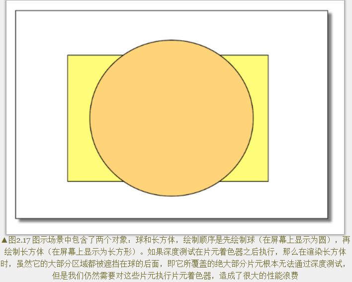
The order of tests given above is not unique, and while it is logical that these tests are run after the fragment shader, for most GPUs they will be run as much as possible before the fragment shader these tests. Prevent the fragments from being discarded after the fragment shader completes the color calculation, which will cause a waste of calculation cost.
The Early-Z technology in the rendering pipeline given by Unity can execute the depth test in advance.
Problems with early testing: If these tests are advanced, their inspection results may conflict with some operations in the fragment shader. For example, if the transparency test is performed in the fragment shader, and the fragment fails the transparency test, we will call the API (such as the clip function) in the shader to manually discard it. This prevents the GPU from performing various tests ahead of time. This prevents the GPU from performing various tests ahead of time.
Solution: Modern GPU will judge whether the operation in the fragment shader conflicts with the early test, and if there is a conflict, the early test will be disabled. However, this will also cause a decrease in performance, because more fragments need to be processed. This is why transparency testing can lead to performance degradation.
target buffer
When the primitives of the model have been calculated and tested layer by layer above, they will be displayed on our screen. What our screen displays is the color value in the color buffer. But to prevent us from seeing those primitives that are being rasterized and operated on a piece-by-piece basis, the GPU will use a double buffering (Double Buffering) strategy.
The rendering of the scene happens behind the scenes, in the Back Buffer . When the rendering is complete, the content in the back buffer and the front buffer (Front Buffer) is exchanged, so as to ensure that the images we see are always continuous.