Preface
This is the first chapter of this tutorial. Are you eager to write code? It's a pity that in this chapter we will not talk about Qt and code, but will talk about some useful and interesting things.
If you write the code directly without thinking, it will make you have some "preconceived" misconceptions, which will become a great obstacle to your later learning process. Therefore, stay calm and read this chapter carefully. Later, when you really learn the code, you will find that tm is the same as when you open it: "Fuck, it turns out that OpenGL is so simple!!!!?"
Being able to read this article shows that you are also a program developer with a high probability. Why did you come to learn OpenGL? Is it because of interest, or is it a job requirement? If you don’t mind, you can share your reason in the comment section
The difference between OpenGL and ordinary drawing API
As a program developer, you may have used some GUI frameworks. Most of these frameworks provide a set of APIs that use CPU for drawing to draw 2D graphics. Such APIs ( hereinafter collectively referred to as ordinary APIs ) generally provide similar to the following Such drawing functions:
画线函数:提供两个端点的坐标来进行绘制
画圆函数:提供圆形坐标和半径来进行绘制
画矩形函数:提供长宽以及其中一个规定点的坐标(一般是左上角,或矩形中心)来进行绘制
画多边形函数:通过一系列的顶点来绘制多边形
画图函数:提供一张外部图像和绘制的矩形区域
....
With these functions, any 2D graphics can be drawn, so why do we still learn OpenGL?
: " Ordinary API can only draw 2D graphics, not 3D graphics, so learn OpenGL."
Wrong! Not because ordinary APIs cannot draw "3D graphics" , but because their drawing efficiency is far from being able to meet the drawing requirements of "3D graphics" . The reason for 3D graphics double quotation marks because they are not true 3D graphics, imagine how a two-dimensional computer screen may show a three-dimensional image of it?
: "Then you mean that ordinary API can also draw 3D graphics?"
Of course, the process of drawing 3D graphics is just to calculate the vertex data of the 3D graphics in an imaginary three-dimensional space , and then map these vertex data from the three-dimensional space to the two-dimensional screen, and finally use these two-dimensional vertex data to draw the graphics. Therefore, the rendering of 3D graphics is essentially a 2D graphics. Since it is a 2D graphics, why can't it be drawn with ordinary APIs ? You only need to understand the "three-dimensional space to two-dimensional space conversion calculation", you can easily accomplish this, if you are interested, you can try.
: "Then what is the difference between OpenGL and ordinary API ?"
Let me tell you a story I made up.
Originally, developers used ordinary APIs for drawing. You can think of yourself as the developer at that time. If you look carefully at the basic drawing functions listed above, you will find that there is a special function-drawing. Polygon function, what is special about it?
Through this function, we can draw any graph, because any graph is composed of vertices.
So does this mean: as long as we optimize the underlying drawing algorithm of this function to the extreme, the efficiency of drawing can be greatly improved?
How to optimize it? By the way, any polygon can be divided into several triangles. If we can find an ultra-high-performance triangle drawing algorithm, wouldn't it work?
But when we turned the theory into reality, we found that the efficiency has indeed improved, but the magnitude is not very large. You continue to optimize the code, but you still cannot meet the requirements of real-time drawing 3D graphics.
You even start to wonder if you are thinking wrong? impossible! If this method does not work, other methods will not work!
Could it be said that real-time 3D graphics rendering is simply a bubble? But if it can be done,...
You still don’t give up, reviewing the written code over and over again, and finally found a breakthrough-there are many similar operations in the code, and there are many operations that can obviously run together, but the computer's processor does not. This is supported. Can I optimize this part of the code by hardware means?
As a result, a processor dedicated to graphics rendering—GPU (Graphics Processing Unit, graphics processing unit) was born. With its appearance, real-time 3D rendering has finally become a reality.
: "Say so much nonsense, where is the difference?"
I thought you understood it, so let me summarize:
Graphic feature processing is different:
- OpenGL (including other GPU drawing APIs) adopts a avenue to simple processing method: disassemble graphics data-describe any graphics through vertex data + primitive types (points, lines, triangles)
- Ordinary API is to divide some basic graphics (points, lines, circles, rectangles...), and use the least features to describe these graphics (for example, describing a circle requires only two parameters: the center coordinate and the radius of the circle)
Different hardware:
- OpenGL uses GPU for graphics drawing
- Ordinary API uses CPU drawing (some ordinary APIs will also convert the code into GPU API to draw through GPU)
The essential difference is caused by:
- Performance difference: GPU drawing is significantly higher than CPU drawing
- Usage difference: ordinary drawing API can use advanced functions to provide a few simple parameters to draw graphics, GPU drawing API requires you to complete the core stage of graphics rendering (take a circle as an example, ordinary API can directly pass the center coordinates of the circle And the radius to draw, while the GPU drawing API focuses on the coordinates of all points on the circle)
Okay, now you may have a preliminary understanding of OpenGL, but would you like to tell me what OpenGL does? You may not be able to tell. why?
: "Because there is no picture! Who can understand it is all text!?"
Understand, I will give you a few larger-scale pictures below.
OpenGL graphics drawing process
(Many people like to call it the graphics rendering pipeline. To be honest, I don’t like the name very much, and I was puzzled when I first saw the name)
In real life, if you want to produce a certain product with extremely high efficiency, then building an automated factory is undoubtedly the best choice. After the building is completed, you only need to provide raw materials, adjust various parts, and press the power supply. When the switch is turned on, the raw materials begin to be transported through the conveyor belt, and are processed by various sub-factories on the way, and finally products are produced.
Below is a cute short video that demonstrates the workflow of the assembly line. It is highly recommended to take a look.
[Baby boss] The baby produced by the assembly line
The drawing of graphics is actually producing products. Therefore, in order to draw graphics efficiently, OpenGL also uses a factory pipeline method, which is why many people like to call this drawing process a graphics rendering pipeline.
Before this, you also need to understand OpenGL standardized device coordinates (Normalized Device Coordinates, NDC)
OpenGL standardized the xyz coordinates to [-1,1] in order to make coordinate calculations independent of the display resolution. Any coordinates that fall outside the range will be discarded/cropped and will not be displayed on your screen (the first step of the pipeline will process the vertex data, you can also normalize the vertex coordinates at this step), and the standardized device coordinates It looks like this

Okay, now we can start to learn the graphics drawing process (graphics rendering pipeline).
The raw material we provide to this factory is vertex data, which will complete the drawing of graphics after six processing stages. The six processing stages are:

The blue part indicates that programming can be performed at this stage. The modern OpenGL rendering pipeline requires you to provide a vertex shader and fragment shader.
It’s okay if you don’t understand this picture. You only need to understand that there are these six stages. The picture itself does not explain the graphics rendering pipeline very well. I will explain these six stages in detail later.
Vertex Data
Do not think that the vertex data here is just vertex coordinates. It can be a collective term for a series of data used to draw vertices, such as vertex color, normal vector, texture coordinates , and vertex coordinates are not necessarily required here.
: "How to draw without vertex coordinates? Draw air?"
Vertex shaders and geometry shaders are all processing data. The actual use of these data starts from the rasterization stage, which means that you can generate vertex data in the process of data processing (for example, if you want to draw a circle, You can only pass in a vertex coordinate and a radius length, and generate circular vertex data in the previous processing stage). Maybe you still don't understand it. After we explain the other stages, you may understand.
These vertex data are passed from the CPU to the GPU, and the transmission is a very expensive process, so the less data transmitted, the better
Since OpenGL generally draws polygons through triangles, such as rectangles, it needs to pass the vertex data of two triangles, that is, 6 vertex data, and 2 of them are repeated. Drawing a rectangle itself only needs 4 vertices, repeat Data incurs an additional 50% overhead, which is obviously not worth the gain. So how does OpenGL solve this problem? You will know in the following tutorials.
Vertex Shader
- Processing vertex data, generally refers to the transformation of vertex data
The translation of shader into shader is easy to misunderstand: Is the shader just used to fill the color? Not really! (Maybe it would be better to call it a vertex processor )
This stage is used to process a single vertex data, so this stage is actually a parallel operation (maybe a lot of vertex data are being processed by this vertex shader program at the same time)
: "How do you deal with it?"
It depends on how you want to deal with the vertex data, because this part needs to implement the code yourself. You can perform various transformation operations such as translation, rotation, and scaling of the vertex coordinates, and modify various vertex data, such as texture coordinates, normal vectors, etc., There is only one principle: it is necessary to ensure that there is only one vertex coordinate in the end, and some data that will be used in other stages are passed and output.
Shape Assembly
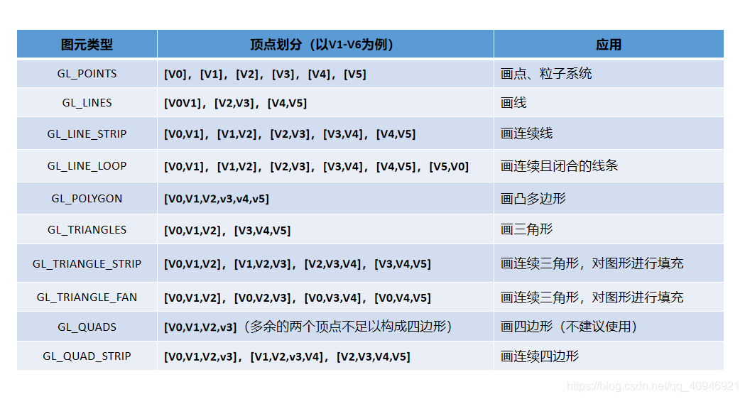
OpenGL supports four basic primitive types: point, line, triangle, and quadrilateral. And provide some extended graphics elements for use, as shown below:

Geometry Shader
- Generate new vertex data (for example, input a vertex, can generate more than 0 new vertex data)
- Modify the output primitive type (for example, if the input primitive is a point, it can output line primitives or triangle primitives)
It can play a certain clipping role, and it can also generate more basic primitives than the vertex shader input .
Several use cases:
Particle system: A particle system is often drawn by GL_POINTS primitives, and particles of various shapes are generated in the geometry shader (it can be 2D or 3D)
Graphics extension: In the chapter of learn OpenGL tutorial-loading 3D model, you can use the geometry shader to generate the normal vector of each vertex of the model (extended by point→line)
Rasterization
- The geometric data after the first two stages of processing is converted into pixels through a series of transformations
For example, if we want to draw a triangle, after the first two stages, we now have the geometric data of the three vertices of the triangle. The purpose of rasterization is to convert the geometric data into pixels after a series of transformations. The process presented on the display device is as follows:

Fragment Shader
- Calculate the color of fragments ("pixels") produced in rasterization
- With a certain cutting function (discard)
This has the same meaning as "shader" in our traditional sense. That's right, the fragment shader is used to fill colors.
Tests
- Filter and process the pixels passed from the fragment processor
The purpose of testing is to filter out the methods we need according to a certain mechanism by setting up some testing methods
OpenGL provides four test methods:
- Depth test: When drawing a three-dimensional object, use the depth test to discard the pixels on the back of the object
- Alpha test: You can discard pixels by alpha value.
- Trimming test: discard pixels by setting the crop area.
- Template testing: Template testing is based on a template to test, its purpose is to allow developers to define their own testing methods.
Blending
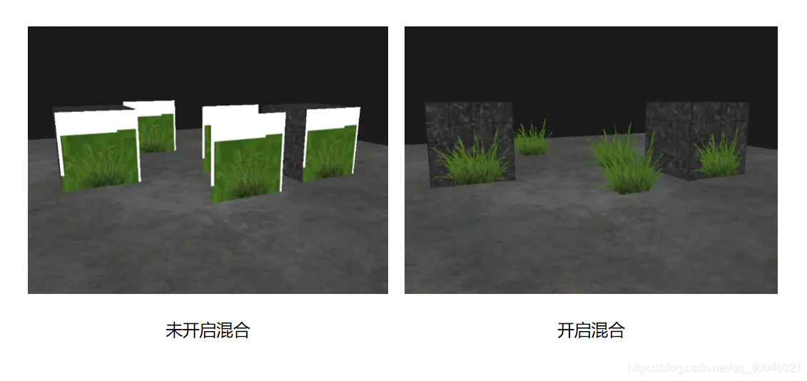
- Blending techniques are often used to express the transparency of objects
The color of a transparent object is often mixed with the color of the object behind it to achieve a transparent effect. The transparency of an object is defined by the value of the alpha channel of the color, such as the picture below:
to sum up
The entire rendering process of OpenGL is roughly the same. After reading it, you may be confused, it doesn't matter, this is normal. In the next tutorial, we will use the code to learn more about OpenGL under the Qt platform step by step.