Firewall principle
Enforce control over inter-region traffic.
Stateful Inspection Firewall.
default region
Huawei: local, trust, untrust, dmz
Cisco: local, inside, outside, dmz
You can add multiple interfaces to the same area, but an interface can only belong to one area.
Traffic communication in the unreachable area is not allowed to pass by default.
The management protocol (generally Telnet/SSH/HTTP/HTTPS/ICMP) policy under the interface takes precedence.
device initialization
Administrators are associated with administrator roles
create admin
Graphical configuration
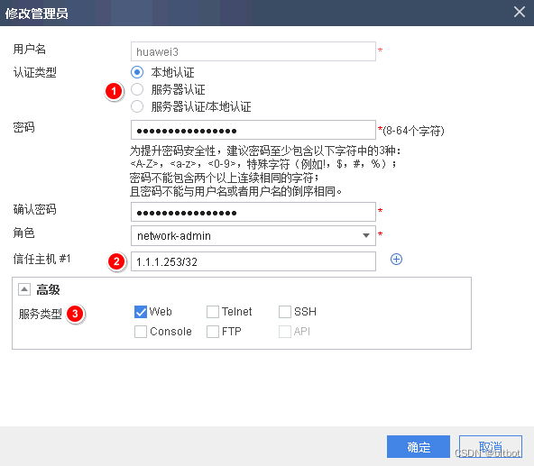
Authentication type:
- Local authentication
Username and password are stored locally - Server Authentication
Username and password are stored on an external server
Trusted host:
means that the terminal IP using this account must match the configured IP address
command line configuration
Correspondence between command line levels and administrator roles
There is no corresponding administrator role for level 0
graphics. The configuration read-only (monitoring) administrator role
for level 1
graphics. The configuration administrator role for
level 2 graphics. The system administrator role for level 3 graphics. Levels 4-15 and Consistent level 3 permissions
The administrator role configured by the graphical interface has a higher priority than that configured by the command line interface!
Complete process of command configuration (emergency)
- aaa
- manger-user username
- level 0-15
- password
- service-type
device management
Graphical management
http/https
command line management
Tools: SecureCRT, xShell, Putty, MobaXterm
Methods: Console (use local account), Telnet (not recommended), Stelnet
Stelnet configuration process:
① The corresponding management interface must activate SSH
② The VTY line must allow the SSH protocol
③ The corresponding account activates the SSH service function
④ Create an RSA key pair
⑤ Activate the SSH function on the managed device
Ping test
file management
current-configuration - not saved, in memory, will be lost upon shutdown
saved-configuration - saved configuration, in Flash, will not be lost upon shutdown
renew
Database update or system update
Local update or network update
interface
Layer 2 interface configuration logic
1) Convert the physical interface to a Layer 2 interface
2) Configure the interface mode
3) Divide VLAN/release VLAN
4) Create a VLAN_IF interface and configure an IP address
5) Allow the corresponding service (determine the configuration according to the requirements)
6) Assign the corresponding interface to corresponding area
Ethernet Link Aggregation
1) Create VLAN
2) Activate physical interface (default activation)
3) Create and configure aggregated interface (eth-trunk)
4) Divide interface into aggregated interface 5
) Create aggregated sub-interface
6) Configure aggregated sub-interface
① Encapsulate VLAN
② IP address
③ Allow the corresponding service
7) Put the corresponding interface into the corresponding area
Load sharing and load balancing
Layer 3 interface configuration
Configure the IP address
Activate the interface (activated by default)
to allow the corresponding service
Add the interface to the zone
routing
floating route
Exclude the standby link from the routing table by down-prioritizing the static/default route
packet-by-packet and stream-by-stream
Packet-by-packet: Judging based on a single data packet, the path of each data packet may be
different The connection will go through another link.
Asynchronous routing: the firewall directly refuses to pass through due to the inconsistency of the back and forth paths!
OSPF Policy Permission
Not all Huawei firewalls need to allow OSPF traffic to establish OSPF neighbors
policy routing
Policy routing has a higher priority than routing entries in the routing table, and can select links for different users/IP/applications
IP-Link is a kind of policy routing health check
Tracert
Processing of detection TTL data packets:
ordinary routing and switching devices reply ICMP data packets directly,
Cisco firewalls will process TTL data packets in a transparent manner,
and Huawei firewalls directly reject them!
IP-Link detection traffic release
Intelligent routing
- Policy routing intelligent route selection
Based on link bandwidth load sharing
Based on link weight load sharing
Based on link quality (packet loss rate, delay, jitter) load sharing
Based on link priority to determine which link to go first - Carrier intelligent route selection
By importing the network segments of China Mobile, China Unicom, China Telecom, and education network into the routing table of the firewall, a static route is formed and forwarded according to the route.
You can check the link of the operator through the health check function, and you can switch if you find a fault! The protocols that can be used for health checks include ICMP, DNS, HTTP, RADIUS, and TCP. - Default route intelligent route selection
Based on link bandwidth load sharing
Based on link weight load sharing
Based on link quality (packet loss rate, delay, jitter) load sharing
Based on link priority to determine which link to go first - packet loss
session hold
Background — Solve the problem of application/game/webpage disconnection caused by link switching and IP address changes.
Three options:
- Source IP address
As long as the source address of the data packet uses the active link, subsequent data packets will always use this link without being affected by the threshold - Destination IP address
As long as the destination address accessed by the data packet uses the active link, subsequent data packets will always use this link without being affected by the threshold - Source/destination IP address
As long as the access between the source address and the destination address of the data packet uses the active link, subsequent data packets will always use this link without being affected by the threshold
source in source out
The traffic coming in from this interface still goes out from this interface!
DNS transparent proxy
Technical background: If an enterprise has two public network links, one for mobile and one for China Unicom. The DNS address issued by the enterprise DHCP is the mobile DNS server. At this time, the DNS requests sent by all devices go through the mobile link, and the responses obtained are also mobile IP, and the Unicom link becomes a decoration.
After deploying a transparent proxy, the USG will automatically determine the forwarding link for the DNS request.
Domain name exclusion: DNS resolution of a specified domain name will not be affected by DNS transparent proxy
Proxy strategy: completely send DNS requests by the firewall proxy PC
Static and dynamic DNS: Static DNS refers to a domain name corresponding to an IP; dynamic DNS refers to a domain name corresponding to a random public network IP.
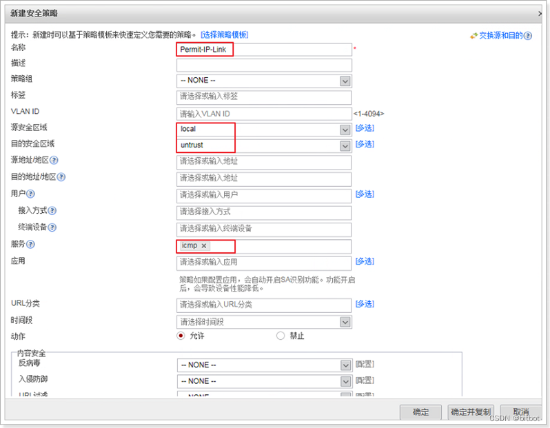
security strategy
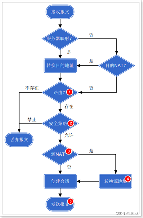
Packet Inspection Process
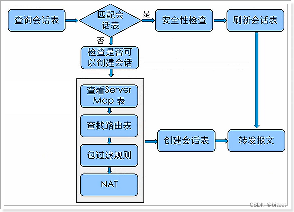
Determine whether it is the first package:
- Judgment result is
to execute further judgment
- Server-map
- routing table
- security policy
- NAT - Judging not (based on the existence of stateful entries)
to perform security content detection (UTM)
checks through direct forwarding
TCP/UDP/ICMP
TCP is a connection-oriented, ordered protocol, and has the concept of the first packet. The firewall must monitor all TCP packets.
UDP is a connectionless and out-of-order protocol. There is no concept of the first packet
and ICMP has no concept of the first packet. The firewall must monitor the ICMP request packet before allowing the ICMP response packet.
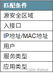
Security policy content
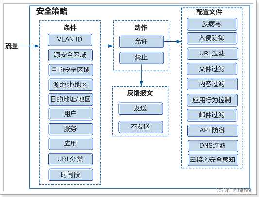
The purpose of sending the feedback message is that the USG discards the connection message and at the same time synchronizes the information to the corresponding server, so that it releases the resources for maintaining the connection.
ASPF
dynamic protocol ftp
active mode
Control channel, based on TCP port number 21, for forwarding control traffic, such as authentication traffic
Data channel, based on TCP port number 20, for forwarding data traffic, such as upload/download
Since control channel and data channel use different port numbers, and In active mode, the data channel is the server connecting to the client, so the stateful entries you see on the firewall are as follows:
ftp VPN: public --> public 5.5.5.2:49172 ±> 10.10.10.1:21
ftp-data VPN: public --> public 10.10.10.1:20 --> 5.5.5.2:49173
The client notifies the server of the IP address and port number of the data channel connection through the PORT command
passive mode
Control channel, based on TCP port number 21, used to forward control traffic, such as authentication traffic
Data channel, based on TCP port number random port, used to forward data traffic, such as upload/download
Since control channel and data channel use different port numbers, And in passive mode, the data channel is for the client to connect to the server, so the stateful entries you see on the firewall are as follows:
ftp-data VPN: public --> public 5.5.5.2:49180 --> 10.10.10.1:49165
ftp VPN : public --> public 5.5.5.2:49178 ±> 10.10.10.1:21
The client queries whether the server supports passive mode through the PASV command. If the server supports it, reply 227+the IP address and port number that the client needs to connect to
Multi-Channel/Dynamic Port Solutions
Based on ASPF technology
1. The USG already has a stateful entry for the flow control channel
2. At the same time, the USG activates the ASPF
display firewall server-map for this protocol
Type: ASPF, 10.10.10.1 -> 5.5.5.2:49182, Zone:—
Protocol: tcp(Appro: ftp-data), Left-Time:00:00:13
Vpn: public -> public
The additional data channel generated by this protocol does not query the security policy, but directly generates the stateful entry of the data channel and allows it to pass.
The hardware firewall has activated ASPF by default for the FTP protocol
The virtualization firewall USGv is not activated by default
address translation
The difference between NAT/PAT
NAT, means to translate the address without forwarding the port number
Static NAT, one-to-one translation, one internal network address corresponds to one public network address
Dynamic NAT, many-to-many conversion, multiple internal network addresses correspond to different public network addresses in a public network address pool
PAT, refers to forwarding address and forwarding port number
Static PAT, one-to-one port translation, one intranet address corresponds to one port number of one public network address, S 1.1.1.1 8080 -> G 2.2.2.2 80
Dynamic PAT, one-to-one port translation, one intranet address corresponds to one The most obvious feature of PAT, the random port number of the public network address
, is that the public network address can be reused. Generally, a public network address can be reused 60,000 times +
one source port corresponds to one port of the public network address, instead of one device corresponding to one The port of the public network address
Paloalto firewall can use the oversubscription technology to realize different intranet addresses and different destination addresses, use the same public network IP + the same port number, and reuse it up to 8 times, that is, 6W*8, nat oversubscription
Source NAT Technology
Convert the private network IP address to the public network IP address, so that private network users can use the public network address to access the Internet
Translate only the source IP address
NAT No-PAT, suitable for scenarios where there are few Internet users and the number of public network addresses is the same as the number of simultaneous Internet users
Convert both the source IP address and the source port number
NAPT is suitable for scenarios where the number of public network addresses is small and the number of private network users who need to access the Internet is large. If there is only one public network address and it has been configured on the public network interface of the egress device, the internal network traffic will be converted to the public network interface address and then access the Internet. —Easy-IP
Smart-NAT, which is only supported by USG9K
, can be used differently for the public network address pool, such as some one-to-one, and some PAT
triplet NAT, which can allow the external network to actively access the internal network for applications
Basic processing flow of source NAT
Cisco ASA security policy to allow NAT traffic:
If the ASA version is before 8.4—the security policy allows the address after translation
If the ASA version is after 8.4—the security policy allows the address before translation
Combination of ASPF and NAT-ALG
ASPF can not only realize the normal traversal of dynamic protocol multi-channels through the USG, but also ensure the normal operation of dynamic protocol traversal address translation technology
. Forward and reverse)
ASPF is activated, and NAT-ALG is activated at the same time
black hole routing
Scenario 1: The translation address is on the same network segment as the USG outbound interface address (source NAT)
Under normal circumstances, when the external device returns a packet, the USG queries the stateful information and the Server-map table based on the IP address and port number of the packet, and forwards it if it matches
. If the USG cannot query the stateful entry of the data packet, it will continue to send ARP requests until the performance of the device is exhausted and
deploy black hole routing. Once it finds that there is no stateful entry, it wants to access the converted The external data packet of the address is directly discarded
Scenario 2: The translation address is in a different network segment from the USG outbound interface address (for NAPT)
Under normal circumstances, when the external device returns a packet, the USG queries the status information and the Server-map table based on the IP address and port number of the packet, and forwards it if it matches. If NAPT is deployed, the NAPT technology itself does not allow the external network to actively access the internal
network , so no Server-map table will be generated.
For this situation, the USG firewall will return the packet to the sending device through the routing table, and the sending device will return the packet to the firewall according to the route, forming a loop to
deploy black hole routing. In the case of NAPT, external network access Intranet data packets, once discovered, are discarded directly, and the USG will no longer forward them
Destination NAT Technology
Destination NAT main function
Used to publish intranet servers or specific services
Server load balancing technology
1. Simple polling
distributes the client's business traffic to each server in
turn 2. Weighted polling
determines the number of requests processed by the server according to the weight
3. Source IP Hash
automatically distributes traffic to different servers according to the HASH algorithm
4. Minimum connection
Allocate traffic to the server with the fewest number of concurrent sessions for processing
Two-way NAT conversion technology
Bidirectional NAT is not a single function, but a combination of source NAT and destination NAT
virtualization technology
A physical firewall is separated into multiple sub-firewalls through physical device virtualization technology, and each sub-firewall is independent.
The difference is that the USG6000V is a software-level device and belongs to NFV.
logical subwall
Have independent administrators, configurations, and routing tables
Traffic forwarding between sub-walls requires policy release
Need to allocate system resources for each sub-wall
Regarding the interface sharing technology,
Cisco firewalls support assigning the same interface to different sub-firewalls at the same time.
Huawei firewalls do not support assigning the same interface to different sub-firewalls at the same time.
Two systems of Huawei physical firewall virtualization technology
root system
The root system is a special virtual system that exists by default on the firewall.
Even if the virtual system function is not enabled, the root system still exists.
The role of the root system is to manage other virtual systems and provide services for communication between virtual systems.
Virtual system VSYS
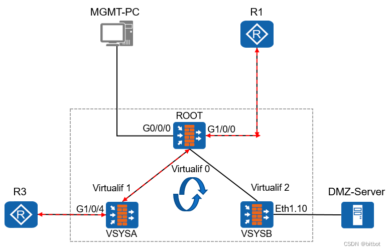
Virtual interface Virtual-IF
It is automatically generated when a virtual system is created. The link layer and protocol layer are always UP
between different virtual systems, and are forwarded through the VIF interface
. In order to allow the release of the security policy, the VIF interface needs to be added to the security zone, but the configuration of the IP address is optional.
VPN instance
Each virtual system has its own independent VPN instance, that is, an independent routing table.
Each virtual system cannot create other VPN instances, nor can it delete its own VPN instance.
The root system also has a VPN instance by default and cannot be deleted.
Management of virtual systems
The administrator of the root system is used to create and manage any virtual system, with the highest authority, which is equivalent to Windows Administrator.
Every virtual system administrator can only manage his own virtual system and cannot manage other virtual systems.
Virtual system administrator account format: Administrator name@@virtual system name, the virtual system name is VSYSA, the administrator name is admin, and the account is admin@@VSYSA
Resource Allocation for Virtual Systems
two types of occupancy
- Quota usage
Manual allocation according to demand
Automatic allocation according to default - shared use
key resource
① session
② integrated strategy
③ user and user group
④ online user and bandwidth
can use two occupation methods
non-critical resource
virtual system forwarding
After the packet enters the firewall, the attribution relationship between the packet and the virtual system must be determined first to determine which virtual system it enters for processing
- Interface-based distribution
Assign the interface to the specified virtual system, and all traffic coming from the specified interface will be processed by the corresponding virtual system - VLAN-based distribution
Bind different virtual systems to different VLANs, and all incoming traffic from the specified VLAN will be processed by the corresponding virtual system
Forwarding processes across virtual systems
Packet forwarding between the virtual system and the root wall
The data packet arrives at VSYSA
VSYSA queries the routing table
VSYSA queries the security policy
If the route exists and the security policy allows it, the next hop of the data packet reaches the root wall through the VIF interface. The root wall forwards the data packet out
of the public network according to the routing table and security policy.
The root wall does not need routing, and directly decides to hand over the data packet to VSYSA for processing based on the stateful table entry. The
external network initiates it. Since there may be no stateful table entry, the root wall needs to add a packet return route.
Packet forwarding from virtual system to virtual system
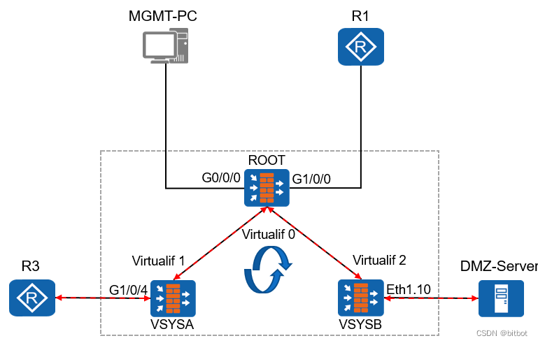
The data packet arrives at VSYSB
VSYSB queries the routing table
VSYSB queries the security policy
If the route exists and the security policy allows it, the next hop of the data packet reaches the root wall through the VIF interface. The root wall forwards
the data packet to VSYSA according to the routing table.
The root wall does not need to release security Policy, as long as the inbound and outbound route exists,
VSYSA can query the routing table and security policy, no problem, that is, forward the data packet
User Management and Authentication Technology
Types of users on the firewall:
users accessing the Internet Access
users—users accessing through VPN
The concept of certification
Verify visitor's identity
Three authentication methods:
- Local Authentication
Perform authentication using the USG local user database - External authentication
Assign the authentication task to an external professional authentication server for execution - single point of authentication
Purpose of certification
It can make the object of log information clearer and analyze and lock faster.
It can make the deployment of security policies more flexible and reduce the situation of security policies caused by human failure.
authentication domain
Determine whether the user or user group belongs to an authentication domain.
Determine the user authentication method (local/server authentication).
By identifying the authentication domain contained in the user name, Huawei Firewall diverts all users to be authenticated to the corresponding authentication domain for authentication. For example: huawei@123, the USG needs to send the huawei account to the 123 domain for authentication. There
is a Default domain by default. If the account is not followed by any parameters, it will be sent to the Default domain for authentication. The default is local authentication.
When creating an account, the user name and password must be configured
How the user triggers authentication
Authentication-free, by binding the specified user name with the IP-MAC of the specified device, the device will be able to access the Internet directly without manual authentication. Applicable scenarios: special equipment, such as printers; high-level company session authentication. When the user initiates network access, the authentication is triggered and the user needs to pass the authentication before continuing to
access the pre- authentication.
Access
Single sign-on: AD domain single sign-on, Radius single sign-on, TSM (Tableau Service Management) single sign-on
Extension: AD domain and Lightweight Directory Access Protocol (LDAP)
can store all user names and passwords that need to be used in the AD domain.
When the user uses the account and password on the AD domain for authentication, the authentication device can extract the user name and password on the AD domain through LDAP. The corresponding account and password are verified. If the extracted username and password are consistent with the sent username and password, the authentication is passed
The role of the Radius protocol is to ensure that the authentication work can be successfully performed between the device and the Radius server
Network Access Service Any device that provides network access services can be called "NAS"
authentication policy
Whether to perform authentication on a flow is determined by the authentication policy.
A flow will only match one authentication policy
. If the flow does not match any authentication policy, the default "default" policy will be used and no authentication will be performed.
Firewall test and ACS connection
The USG6507 can directly execute the test without allowing the firewall; the USG6307 needs to allow the traffic from the local to the ACS to perform the test
Hot Standby
Avoid single point of failure affecting the normal use of the production network
Huawei dual-system hot backup technology architecture
VRRP Gateway Redundancy Protocol
The multicast address is 224.0.0.18, and the protocol number is 112.
Based on the VRRP protocol, two USGs are virtualized into one, providing external services.
VRRP provides equipment failure detection and traffic switching functions.
normal circumstances
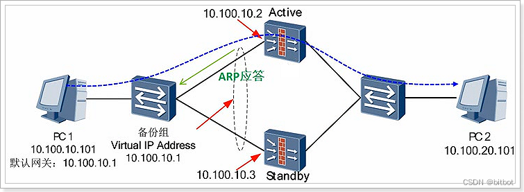
1) The virtual IP address takes effect on the device interface whose status is Active
2) Only the Active device responds to the gateway ARP request sent by the PC
3) The business traffic is directed to the Active device for processing
When a fault is triggered
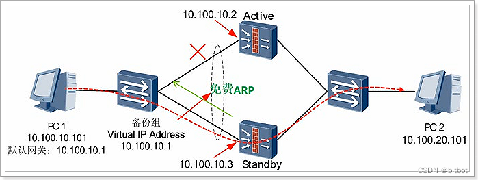
1) The VRRP backup group on the Active device interface enters the Initialize state
2) The VRRP backup group on the Standby device interface switches to the Active state
3) Send gratuitous ARP in broadcast mode, refresh the MAC address table on the switch, and redirect the outgoing interface to the standby Device
4) The traffic sent by the PC is diverted to the Standby device
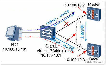
Problems Existing in VRRP Technology
The state of the upper and lower VRRP groups is not synchronized, which may directly lead to routing black holes!
Solve this problem by introducing the "VGMP" protocol!
VGMP VRRP group management protocol
Put multiple VRRPs into the same VGMP group, if any VRRP in the same group switches, other VRRPs will also switch accordingly.
VGMP determines the firewall priority and active/standby status.
Three principles for state switching:
1) Whenever an interface is Down, the priority of the VGMP management group is reduced by 2 (optional)
2) The initial state of the VGMP management group of each device is specified by the user (Active or Standby)
3) Active takes precedence The priority level is 65001, and the priority level of Standby is 65000
4) The status of the VGMP management group determines the active and standby status of the device, as well as the status of the members of the VGMP management group
Fault detection
Direct connection fault detection
Detect VRRP status
Detect Layer 3 interface
Detect VLAN interface
Indirect Fault Detection
IP-LINK
Advantages: no peer support is required, the local device can be directly deployed
Disadvantages: the detection speed is slower than BFD
Public protocol
BFD
Advantages: The speed is faster than IP-LINK
Disadvantages: The peer device needs to support the BFD
public protocol at the same time, based on UDP port number 3784
traffic guidance
Uplink and downlink the Layer 2 network, and the firewall itself uses a Layer 3 interface
1. The IP address of the next hop of the device is the VRRP virtual IP address
2. When the VRRP status changes, the new active device refreshes the MAC address tables of all switches through free ARP and redirects the traffic to itself
3. When other When the device sends a request for a virtual IP address, only the active device responds
The upper and lower layers of the network, the firewall itself uses the layer 3 interface, and is in active and standby mode at the same time
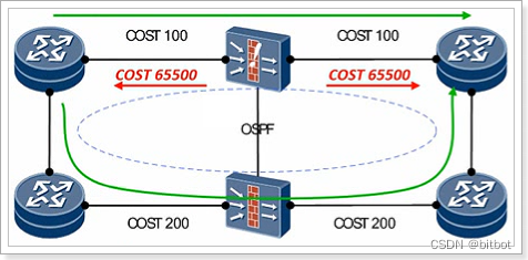
1. The active and standby firewalls establish dynamic routing neighbors with the upstream and downstream devices at the same time.
2. The standby firewall actively increases the COST value to 65500, and the business traffic is uniformly directed to the active device for processing.
3. When a fault occurs, the original active firewall increases the COST value to 65500. Service traffic is uniformly guided to the original and standby equipment for processing
Uplink and downlink three-tier network, the firewall itself uses a three-tier interface, and is in load sharing mode at the same time
Does not require VGMP to perform any operations, and is directly monitored by the dynamic routing protocol
The firewall itself uses a layer 2 interface and is in active and standby mode at the same time
① In this mode, VLAN is bound to VGMP.
② Under normal circumstances, the VLAN on the active wall can forward data normally,
and the VLAN on the backup wall is disabled. The original firewall VLAN performs forwarding
HRP Huawei Redundancy Protocol
Realize the backup of configuration and state information—realize the backup of dynamic state data and key configuration commands between two firewalls
Data backup content
Stateful information backup content
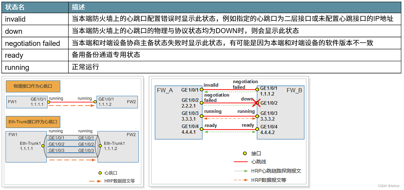
Heartbeat State Machine
History of High Availability
Active/standby mode
Two devices, one active and one backup.
Disadvantage, the backup device is not fully utilized!
load sharing mode
Two devices, working at the same time
Cluster High Availability Mode Cluster
Cisco supports up to 16 firewall clusters to achieve high availability!
All firewalls are working, and there is no active/standby mode!
The performance of the firewall for the cluster will be superimposed!
Cloud Computing Server High Availability Technology
Computer Resource Scheduling Automation DRS
Realize the server load judgment in the cluster, and the high-load server will reduce the pressure according to the DRS strategy
Power Automation Management DPM
When the overall utilization rate of a cluster server is lower than the set policy, activate DPM to concentrate limited services into one device, and the rest of the devices will enter standby mode to achieve green energy saving
Network attacks
DDoS, single packet attack, layer 2 attack
VPN
MPLS VPN, IPsec VPN, L2TP VPN, SSL VPN, GRE VPN
Agile Controller
UTM
AV
IPS
URL Filtering
Content Filtering
File Filtering
Email Filtering
Application Behavior Control
APT