Table of contents
Classification according to usage characteristics
Classified according to transmission speed
Classification by units of information exchange
Functions of the IO controller
The composition of the IO controller
Independent addressing of memory-mapped IO and registers
How the operating system manages the logical device table
The flow of the interrupt handler
The birth of spooling technology
Principle Analysis of Shared Printer
Distribution and recycling of equipment
Factors to consider when assigning equipment
Intrinsic properties of the device
Static allocation and dynamic allocation
Data Structures in Device Allocation Management
Relationship between devices, controllers, and channels
Improvements to the device assignment step
The difference between using single/double buffering in communication
The specific use of the buffer pool
The concept of IO device
Meaning: I/O is input/output (input/output); an IO device is an external device that can input data to a computer or receive data output from a computer, and belongs to the hardware part of the computer.
Notice:
- The UNIX system abstracts the external device into a special file, and the user can operate the external device in the same way as the file operation
- write operation: write data to an external device
- read operation: read data from an external device
Classification of IO devices
Classification according to usage characteristics
- Human-computer interaction external devices: devices that are often used to interact with computers (slow data transmission speed) - mouse, keyboard
- Storage devices: devices for data storage (fast data transfer speed) - mobile hard disk, CD
- Tongnet communication equipment: A device used for network communication (data transmission speed is in between) - modem
Classified according to transmission speed
- low speed equipment
- Medium speed equipment
- high speed equipment
Classification by units of information exchange
- Block device: The basic unit of data transmission is "block", which has a high transmission rate and is addressable, that is, it can randomly read/write any block - disk
- Character device: the basic unit of data transmission is character, the transmission rate is slow, it is not addressable, and the interrupt-driven method is often used in input/output - mouse, keyboard
I/O controller
Composition of IO devices
- Mechanical components: mainly used to perform specific IO operations, such as the mouse and keyboard buttons we can see and touch (LED screen of the monitor, magnetic arm of the mobile hard disk, disk surface)
- Electronics: Usually a printed circuit board (IO controller, device controller) that plugs into a motherboard expansion slot
Note: When our IO devices are connected to the computer, the CPU cannot directly control the mechanical parts of the IO devices. It must indirectly control the mechanical parts through electronic parts (IO controllers, also known as device controllers).
Functions of the IO controller
- Receive and identify commands sent by the CPU: such as read/write commands sent by the CPU, there will be corresponding control registers in the IO controller to store commands and parameters
- Report the status of the device to the CPU: There will be a corresponding status register in the IO controller to record the current status of the IO device. For example: 1 means free, 0 means busy
- Data exchange: The corresponding data registers will be set in the IO controller. When outputting, the data register is used to temporarily store the data sent by the CPU, and then the controller transmits the device. When inputting, the data register is used to temporarily store the data sent by the device, and then the CPU takes the data from the data register
- Address identification: Similar to the address of the memory, in order to distinguish each register in the device controller, it is also necessary to set a specific address for each register. The IO controller judges which register the CPU wants to read/write through the address provided by the CPU
The composition of the IO controller
- The interface between the CPU and the controller: used to realize the communication between the CPU and the controller. The CPU issues commands through the control line; specifies the device to be operated through the address line; takes out input data or puts in output data through the data line
- IO logic: responsible for receiving and identifying various commands of the CPU (such as address decoding) and responsible for issuing commands to the device
- The interface between the controller and the device: used to realize the communication between the controller and the device
specific process

- The CPU will send a specific IO command to the IO logic through the control line, and at the same time, the CPU will also indicate on the address line which device it is operating. The data to be output is placed in the data register of the IO controller, and then the IO logic can obtain the data that the CPU wants to output from the data register. The IO command sent by the CPU may have some parameters, and these parameters will be placed in the control register. , the IO logic can get the corresponding parameters from the control register; in order to realize the management of each data, the CPU will also read the status of each device from the status register (busy, idle, fault, etc.) The IO logic will write corresponding data to the status register to tell the CPU the status of each device;
- The IO logic takes out the data output by the CPU from the data register, takes out the control parameters from the control register, and outputs these data to the controller device interface of the corresponding address. state for the CPU to know about
Notice:
- An IO controller may be responsible for controlling multiple specific IO devices. In order to distinguish which device the CPU is operating, it is necessary to give the device interface an address number
- There are control registers, status registers, and data registers in the interface between the CPU and the controller; and there may be multiple registers (each control/status register corresponds to a specific device), and these registers must have corresponding addresses to facilitate the CPU operate. Some computers allow these registers to occupy part of the memory address, called memory image IO; other computers use IO-specific addresses, that is, registers are independently addressed
Independent addressing of memory-mapped IO and registers
- Memory image IO: The registers in the controller and the memory address are uniformly addressed (the instructions are simplified, and the instructions for operating the memory can be used to operate the controller)
- Independent addressing of registers: registers in the controller use separate addresses (need to set special instructions to realize the operation of the controller, not only specify the address of the register, but also specify the number of the controller)

IO control method
direct program control

Read operation: The CPU sends a read instruction to the IO logic of the IO controller through the control line, and at the same time, the CPU will also indicate on the address line which device it is operating, so the device starts, and the status register is set to 1 (not ready ), so the device starts to prepare the data that the computer wants to read in, but the speed of the device is much slower than that of the CPU, so the CPU will continuously poll and check the status of the controller before the device completes the IO, if the status is always 1 It means that the device is busy and has not prepared data. If the input device is ready for data, it will pass the data to the data register through the IO logic, and report its status as ready to the status register through the IO logic; CPU polling When the status of the device is ready, the CPU can read the corresponding data from the data register (the CPU will first read the data in the data register into its own register, and then put the contents of the CPU register into the memory)

interrupt driven
Preface: The interrupt mechanism is introduced. Since the IO device is very slow, after the CPU issues a read/write command, the IO process can be blocked and switched to other processes for execution. When the IO is completed, the controller will send an interrupt signal to the CPU. After the CPU detects the interrupt signal, it will save the running environment information of the current process and transfer to execute the interrupt handler to handle the interrupt. During the interrupt processing, the CPU reads a word of data from the IO controller and transfers it to the CPU register, and then writes it into the main memory. Then the CPU restores the running environment of the process waiting for IO or other processes, and then continues to execute
Notice:
- The CPU checks for interrupts at the end of each instruction cycle
- During the interrupt processing process, it is necessary to save and restore the running environment of the process. This process requires a certain amount of time overhead. It can be seen that if the interrupt frequency is too high, it will also affect the system performance.

DMA mode
Preface: Compared with the interrupt-driven method, DMA (direct memory access. Mainly used for IO control of block devices) has several improvements
- The unit of data transmission is a block, no longer a word-by-word transmission;
- The flow of data is directly from the device to the memory, or directly from the memory to the device, no CPU is required for transfer
- CPU intervention is only required at the beginning and end of the transfer of one or more data blocks

DMA controller

- DR (data register, data register): temporarily store data from the device to the memory, or from the memory to the device
- MAR (memory address, memory address register): When inputting, MAR indicates where the data should be placed in the memory; when outputting, MAR indicates where the data to be output should be placed in the memory
- DC (data counter, data counter): Indicates the number of bytes remaining to be read and written
- CR (command register, command/status register): used to store IO commands sent by the CPU, or device status information
Notice:
- The system bus will connect the DMA controller and the memory, so the data can be read and written directly between the DMA controller and the memory
- The DMA controller does not directly read in a whole block of data each time, but directly puts a whole block into the memory; in fact, the DMA controller also reads in the data word by word, and reads in one word at a time. Words will be placed in DR first, and then written from DR to memory

Channel control method
Preface: The so-called channel is actually a kind of hardware, which can be understood as a weak chicken version of the CPU. The channel can recognize and execute a series of channel commands
How channels work
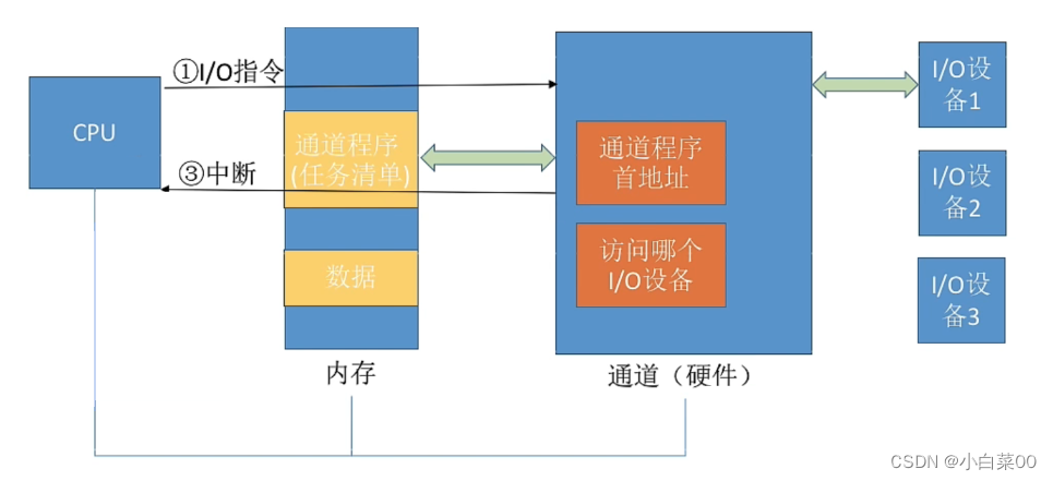
- The CPU, memory, and channels are connected together through the system bus. First, the CPU sends IO commands to the channels. And indicate where the sequence of channel program channel instructions to be executed is stored in the memory, and indicate the IO device to be operated, and then the CPU can switch to other processes to run
- The channel will find out where the channel program (task list) to be executed is stored in the memory according to the instructions of the CPU, and execute the channel program (which specifies how much data to read/write. The read and write data should be placed Where in the memory, etc.)
- After the channel executes the specified tasks, it sends an interrupt signal to the CPU, and then the CPU processes the interrupt
Note: The channel can recognize and execute a series of channel instructions, but compared with the CPU, the channel can execute a single instruction, and the channel program is placed in the host memory, which means that the channel shares memory with the CPU

Summarize

Hierarchy of IO software

Notice:
- In these hierarchies, the closer to the upper layer, the closer to the user, and the lower, the closer to the hardware
- Each layer will use the functions provided by the software of the layer below them, and provide some services to the software of the upper layer
- Each layer will use the services provided by its lower layer to implement certain functions, and shield the implementation details to provide services to the upper layer (encapsulation idea)
- When the user initiates an IO request, the IO request will be processed from top to bottom through various levels, and finally thrown to the IO hardware to perform the actual IO operation. When the IO hardware completes these IO operations and sends an IO response, it will be sent by These levels are processed sequentially from bottom to top and finally returned to the user
user-level software
Understanding: The user layer software implements the interface for interacting with the user, and the user can directly use the library functions related to IO operations provided by this layer to operate the device.
Notice:
- The user layer software translates the user's request into a formatted IO request, and requests the service of the operating system kernel through a system call
- The windows operating system provides a series of system calls, but due to the strict format of the system calls, it is troublesome to use, so a series of more convenient library function interfaces are encapsulated on the user layer for users to use (windows API)
Device Independent Software
Meaning: Device independent software, also known as device independent software. Almost all functions that have nothing to do with the hardware characteristics of the device are implemented at this layer
Implemented functions
- Provide a unified call interface to the upper layer (such as system calls such as read/write)
- Protection of devices (the principle is similar to file protection. Devices are regarded as a special file, and different users have different access rights to each file. Similarly, the access rights to devices are also different)
- Error handling (device independence software needs to handle errors of some devices)
- Distribution and recovery of equipment
- Data buffer management (differences in data exchange unit size and transmission speed between devices can be shielded by buffer technology)
- Establish a mapping relationship between logical device names and physical device names; select and call the corresponding driver according to the device type (when the user or user layer software issues a system call related to the IO operation system call, it is necessary to specify the logical device of the IO device to be operated name)
logical device table

Notice:
- The device independent software needs to determine the physical device corresponding to the logical device through the logical device table (LUC), and find the device driver corresponding to the device
- IO devices are treated as a special kind of file
- Different types of IO programs need to be handled by different drivers
How the operating system manages the logical device table
- Only one LUT is set for the entire system, which means that all users cannot use the same logical device name, so this method is only applicable to single-user operating systems
- One LUC is set for each user, and the logical device names used by each user can be repeated, which is suitable for multi-user operating systems. The system will create a user management process for the user when he logs in, and the LUC is stored in the PCB of the user management process for a long time
device driver
Preface: The device driver is mainly responsible for the specific control of the hardware device, converting a series of commands (such as read/write) issued by the upper layer into a series of operations that the specific device can understand. Including setting device registers, checking device status, etc.
Note: The driver generally exists as an independent process
interrupt handler
Preface: When the IO task is completed, the IO controller will send an interrupt signal, and the system will find and execute the corresponding interrupt handler according to the type of the interrupt signal.
The flow of the interrupt handler

hardware
Preface: Different IO devices have different hardware characteristics, and only the manufacturer of the device knows the specific details. Therefore, the manufacturer needs to design and provide the corresponding hardware driver according to the hardware characteristics of the device
Function: perform IO operation, composed of mechanical parts and electronic parts
The core subsystem of IO
Preface: Device independence software, device drivers, and interrupt handlers belong to the kernel part of the operating system, that is, the IO system or the IO core subsystem

Note: The spooling technology (SPOOLing technology) needs to request the service of the device independence software of the disk device, so generally speaking, the spooling technology is implemented by the user-level software. But the 408 outline classifies the spooling technology as a function of the IO core subsystem.
Spooling technology
offline technology
Offline: Perform input/output operations without the control of the host.


Note: After the offline technology is introduced, the speed conflict between the CPU and the slow IO device is alleviated. In other words, even if the CPU is busy, the data that needs to be calculated can be input to the tape in advance, even if the output device is busy, the data can be output to the tape first
The birth of spooling technology
Preface: Based on the idea of offline technology, people have studied spooling technology, also known as SPOOLing technology, which simulates offline technology by software
Notice:
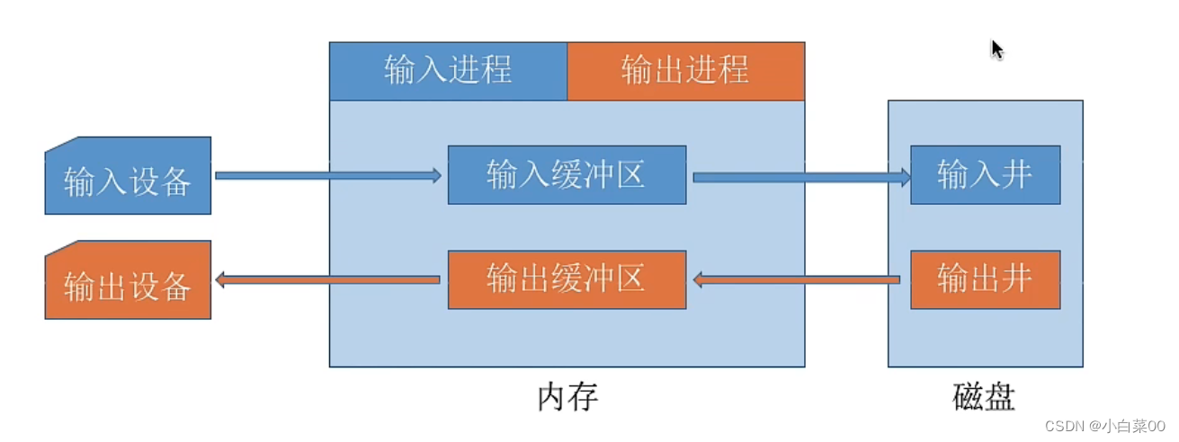
- The system will open up two storage areas on the disk - the input well and the output well
- The input well simulates the tape during offline input, which is used to store the data input by the IO device
- The output well simulates the tape during offline output, which is used to store the data output by the user process
- The input process is used to simulate the peripheral control machine during offline input, and the output process simulates the peripheral control machine during offline output
- To realize SPOOLing technology, it must be supported by multi-programming technology
- The input buffer and output buffer are mainly used as data transfer stations when simulating offline technology
Principle Analysis of Shared Printer
Exclusive and Shared Devices
- Exclusive device: A device that is only allowed to be used serially by each process. Only one process request can be satisfied at a time
- Shared device: A device that allows multiple processes to use it at the same time (macroscopically used at the same time, microscopically may be used alternately) can satisfy the use requests of multiple processes at the same time
Preface: The printer is an exclusive device (if process 1 is using the printer, process 2 will inevitably cause blocking when requesting to use the printer), but it can be changed to a shared device with SPOOLing technology

When multiple user processes make output printing requests, the system will grant their requests, but it does not actually assign printers to them, but the spool management process does the following for each process
- Apply for a free buffer for the process in the disk output well (that is, this buffer is on disk) and send the data to be printed into it
- Apply for a blank print request form for the user process, and fill the user's print request into the form (in fact, it is used to explain the user's print data storage location and other information) and then hang the form on the spool file queue
- When the printer is idle, the output process will take out a print request table from the head of the file queue, and transfer the data to be printed from the output well to the output buffer according to the requirements in the table, and then output to the printer for printing. In this way, all printing tasks can be processed sequentially
Summary: SPOOLing technology can virtualize a physical device into multiple logical devices, and can transform an exclusive device into a shared device
I/O scheduling
Meaning: Use some algorithm to determine a good order to process each IO request
Such as disk scheduling (first-come-first-serve algorithm, shortest seek first algorithm, SCAN algorithm, C-SCAN algorithm, LOOK algorithm, C-LOOK algorithm) when multiple disk IO requests arrive, use a certain scheduling algorithm to determine that the IO request is satisfied Similarly, printers and other devices can also use first-come-first-serve algorithms, priority algorithms, short job priority algorithms, etc. to determine the order of IO scheduling
equipment protection
- The operating system needs to implement the file protection function, and different users have different access rights to each file (such as: read-only, read and write, etc.)
- In the Unix system, the device is regarded as a special file, and each device will have a corresponding FCB. When a user requests to access a certain device, the system judges whether the user has corresponding access rights according to the information recorded in the FCB, so as to realize the function of device protection
Distribution and recycling of equipment
Factors to consider when assigning equipment
- Intrinsic properties of the device
- Device Allocation Algorithm
- Security in Device Allocation
Intrinsic properties of the device
- Exclusive device: can only be assigned to 1 process in a period of time (such as a printer)
- Shared device: It can be allocated to multiple processes at the same time (such as disks). Each process often shares the device at the same time on a macro level, and uses it alternately on a micro level
- Virtual device: use SPOOLing technology to transform the exclusive device into a virtual shared device, which can be allocated to multiple processes at the same time (such as a shared printer implemented by SPOOLing technology)
Device Allocation Algorithm
- first come first serve
- higher priority first
- short task first
Device Allocation Security
Security distribution method
Meaning: After allocating a device to the process, the process will be blocked, and the process will be woken up after this IO is completed (only one device can be used in a period of time)
Advantages and disadvantages
- Advantages: Destruction of request and hold conditions, no deadlock
- Disadvantage: For a process, CPU and IO devices can only work serially
insecure distribution
Meaning: After a process sends out an IO request, the system allocates an IO device for it, the process can continue to execute, and then a new IO request can be issued. The process is blocked only when an IO request is not satisfied (a process can use multiple devices at the same time)
Advantages and disadvantages
- Advantages: The computing tasks and IO tasks of the process can be processed in parallel, so that the process can advance rapidly
- Disadvantage: Deadlock may occur
Static allocation and dynamic allocation
- Static allocation: all the required resources are allocated to the process before it runs, and the resources are returned after the run ends
- Dynamic allocation: dynamically apply for device resources during process running
Data Structures in Device Allocation Management
Relationship between devices, controllers, and channels

Note: One channel can control multiple device controllers, and each device controller can control multiple devices
Device Control Table
Preface: The system configures a device control table (DCT) for each device to record the status of the device

Controller Control Table
Preface: Each device controller will correspond to a controller control table (COCT). The operating system operates and manages the controller according to the COCT information

Channel Control Table
Preface: Each channel will correspond to a channel control table (CHCT). The operating system manipulates and manages the channel according to the information of CHCT

System Equipment Table
Preface: The system device table (SDT) records the conditions of all devices in the system, and each device corresponds to an entry

Device allocation steps

Note: Only when the device, controller, and channel are all assigned successfully, the device assignment is considered successful, and then the IO device can be started for data transmission
shortcoming:
- The user must use the physical device name when programming, and the underlying details are opaque to the user, which is inconvenient for programming
- If another physical device is used, the program cannot run
- If the physical device requested by the process is busy, the process must block and wait even if there are devices of the same type in the system
Improvements to the device assignment step
Preface: Due to the shortcomings of the original device allocation step, a mapping mechanism between logical device names and physical device names can be established, and users only need to provide logical device names when programming

Logical Unit Table (LUC)
Preface: The logical device table establishes the mapping relationship between logical device names and physical device names

Notice:
- When a user process uses the device for the first time, it uses the logical device name to send a request to the operating system. The operating system searches the system device table according to the device type (logical device name) specified by the user process, finds an idle device and assigns it to the process, and lists it in the LUC Add corresponding entries
- If the user process requests to use the device again through the same logical device name, the operating system can know which physical device the user process actually wants to use through the LUC table, and can also know the device driver entry address
Problem with setting up the logical device table
- There is only one LUC in the whole system: the logical device names used by each user are not allowed to be duplicated, which is suitable for single-user operating systems
- One LUC for each user: the logical device names of different users can be repeated, suitable for multi-user operating systems
buffer management
What is a buffer zone
Meaning: A buffer is a storage area that can be composed of specialized hardware registers or use memory as a buffer
Notice:
- The cost of using hardware as a buffer is relatively high, and the capacity is relatively small. It is generally only used in occasions that require very high speed (such as the associative register used in memory management, because the access frequency to the page table is extremely high, so the use speed is very high fast associative registers to store copies of page table entries)
- In general, more memory is used as a buffer, and the buffer management of device independence software is to organize and manage these buffers
The role of the buffer

single buffer
Preface: Assuming that a user process requests a certain block device to read several blocks of data, if the single buffer strategy is adopted, the operating system will allocate a buffer for it in the main memory (if not specified in the title, the size of a buffer size is one block)
Notice:
- When the buffer data is not empty, data cannot be flushed into the buffer, and data can only be transferred from the buffer;
- When the buffer is empty, you can flush data into the buffer, but you must fill the buffer before you can transfer data from the buffer
use of single buffering
Understanding: First, the system allocates a buffer of a size for the user process in the main memory, then the block device will generate a block of data and input it into the buffer; after the buffer is full, the data in it needs to be transmitted to the user The process work area can be processed by the user process; then the user process can process the block of data through the CPU; when the processing is completed, the work area of the user process will be vacated.

double buffering
Preface: Assuming that a user process requests a certain block device to read several blocks of data, if the double-buffering strategy is adopted, the operating system will allocate two buffers in the main memory (if not specified in the title, one buffer’s size is one piece)
The difference between using single/double buffering in communication
Preface: When communicating between two machines, you can configure the buffer for sending and receiving data


Notice:
- If two machines communicating with each other only set up a single buffer, only one-way transmission of data can be realized at any time
- If two machines communicating with each other set up double buffers, bidirectional data transmission can be realized at the same time
- The pipeline in pipeline communication is actually a buffer. To achieve bidirectional transmission of data, two pipelines must be set up
circular buffer
Preface: In many cases, only 2 buffers still cannot meet the actual needs of the process, so the operating system can allocate multiple buffers of equal size to the process, and let this buffer be connected into a circular queue, which is the circular buffer

Notice:
- In the figure above, orange indicates a buffer that is already full of data, and green indicates an empty buffer
- The system keeps two pointers for buffer management
buffer pool
Preface: The buffer pool consists of shared buffers in the system. These buffers can be divided into: empty buffer queue, buffer queue full of input data (input queue), buffer queue full of output data (output queue) according to usage status
Simple understanding: a pool full of various buffers, when we need to use a buffer or return a buffer, we can operate on various buffers in this pool

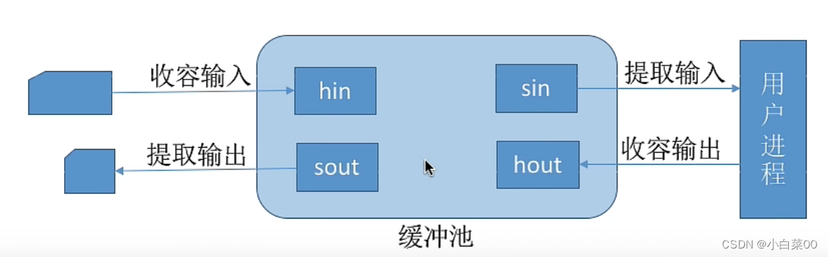
In addition, according to the different functions of a buffer in actual operation, four buffers are set up: the working buffer (hin) for storing input data, the working buffer (sin) for extracting input data, and the working buffer (sin) for storing input data. A working buffer (hout) for storing output data and a working buffer (sout) for extracting output data
The specific use of the buffer pool
- The input process requests input data: the system will take an empty buffer from the head of the empty buffer queue and use it as a hin. When the buffer is full, it will be hung at the end of the input queue
- The calculation process wants to obtain a piece of input data: the operating system will take a buffer from the head of the input queue and use it as sin, and the data in this buffer will be transferred to the work area of the calculation process, so this buffer The data in the area is emptied and placed at the end of the empty buffer
- The calculation process flushes the ready data into the buffer: the operating system will take an idle buffer from the head of the empty buffer queue and use the buffer as a hout, so the buffer will be filled and placed in the output buffer District team tail
- The output process requests output data: the system will take a buffer from the head of the output queue and use it as sout, and then the data in the buffer will be emptied, and then hung to the end of the free buffer queue