overall scheme design
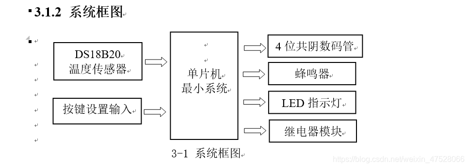
3.1.1 System overview
The whole system uses STC89C52 single-chip microcomputer as the core device, and cooperates with resistors, capacitors, crystal oscillators and other devices to form the smallest system of single-chip microcomputer. The other modules revolve around the minimum system of single-chip microcomputer. Among them, the sensor adopts DS18B20, which is responsible for collecting temperature data and sending it to the microcontroller. The display device adopts 4 common negative digital tubes to display the detected temperature value. The button module is mainly used to set the alarm value. The alarm module adopts the mode of buzzer + LED, and it will give an audible and visual alarm if it exceeds the alarm range. At the same time, there are heating and cooling devices to keep the temperature within a certain range.
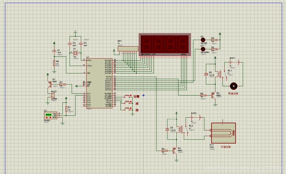
Schematic:

Simulation diagram:
Minimum system module
3.2.1 Introduction to STC89C52
(1) Overview
STC89C52 is a low-voltage, high-performance CMOS 8-bit microcontroller, which contains 8k bytes rewritable Flash read-only program memory and 256 bytes random access data memory (RAM), the device is produced by ATMEL's high-density, non-volatile storage technology, compatible with the standard MCS-51 instruction system, with a built-in general-purpose 8-bit CPU and Flash storage unit, and the powerful STC89C52 microcontroller can provide you with Many more complex system control applications.
STC89C52 has 40 pins, 32 external bidirectional input/output (I/O) ports, and includes 2 external interrupt ports, 3 16-bit programmable timing counters, 2 full-duplex serial communication ports, 2 A read and write port line. STC89C52 is available in three packages: PDIP, PQFP/TQFP and PLCC, to meet the needs of different products.
(2) Main features
Compatible with MCS51 instruction system;
8k rewritable (>1000 times) Flash ROM;
32 bidirectional I/O ports;
256x8bit internal RAM;
3 16-bit programmable timer/counter interrupts;
Clock frequency 0-24MHz;
2 serial interrupts;
Programmable UART serial channel;
2 external interrupt sources;
A total of 8 interrupt sources;
2 read-write interrupt lines;
3-level encryption bits;
low-power idle and power-down modes
;
DS18B20 sensor circuit
3.3.1 Introduction to DS18B20
(1) Overview
DS18B20 (Figure 3-4) is the first temperature sensor that supports the "one-line bus" interface launched by DALLAS Semiconductor Corporation in the United States. It has miniaturization, low power consumption, and high performance. , Strong anti-interference ability, easy to match the microprocessor and other advantages, can directly convert the temperature into a digital signal processor for processing. The measured temperature range is -55 to 125°C, and the temperature measurement error is 0.5°C. The programmable resolution is 9 to 12 bits, and the corresponding resolvable temperatures are 0.5°C, 0.25°C, 0.125°C and 0.0625°C. Compared with thermocouple sensors, it can achieve high-precision temperature measurement.
(2) Features
The unique 1-Wire bus interface only needs one pin to communicate;
each device’s internal ROM has a unique 64-bit serial number programmed; the
multi-channel acquisition capability makes distributed temperature acquisition applications easier ;
No external components required;
power supply range is 3.0V to 5.5V;
temperature measurable range is: -55°C to +125°C (-67°F to +257°F);
temperature range exceeds -10°C to 85°C Accuracy of ±0.5°C;
internal temperature acquisition accuracy can be user-defined from 9-Bits to 12-Bits;
temperature conversion time reaches a maximum value of 750ms when the conversion accuracy is 12-Bits;
user-defined non-volatile temperature Alarm setting;
defines the temperature alarm search command and when the temperature exceeds the user-defined set value;
compatible with the DS1822 program.
(3) Pin definition
Pin1: (VDD), optional power supply pin;
Pin2: (DQ), data input/output pin for single-line use;
Pin3: (VDD), ground terminal, power supply negative pole;
(4) Application field
This product is suitable for freezer, granary, storage tank, telecommunication room, electric machine room, cable duct, etc.
Temperature measurement and control of industrial equipment in narrow spaces such as bearing bushes, cylinder blocks, textile machinery, air conditioners, etc.
Automotive air conditioners, refrigerators, freezers, and medium and low temperature drying ovens, etc.
Heating/cooling pipeline heat metering, central air-conditioning household heat energy metering and temperature measurement and control in industrial fields.
Nixie tube display module
3.4.1 Nixie tube introduction
Nixie tube is a kind of cheap price and easy to use. By inputting relative current to its different pins, it will light up, thus displaying numbers that can display time, date, temperature, etc. A device whose parameters can be expressed numerically. It is widely used in electrical appliances, especially household appliances, such as display screens, air conditioners, water heaters, refrigerators, etc. LED digital tubes (LED Segment Displays) are packaged together by multiple light-emitting diodes to form an "8"-shaped device. The leads have been connected internally, and it is only necessary to lead out their individual strokes and common electrodes. The digital tube is actually composed of seven light-emitting tubes in a figure-eight shape, and adding a decimal point is eight. These segments are represented by the letters a, b, c, d, e, f, g, dp, respectively. When voltage is applied to specific segments of the digital tube, these specific segments will light up to form the words that our eyes see. For example: if a word "2" is displayed, then a should be on, b on, g on, e on, d on, f off, c off on dp, off on. The shape of the digital tube is shown in Figure 3-8.
LED digital tubes are divided into general bright and super bright, and also have different sizes such as 0.5 inch and 1 inch. The display strokes of small-sized digital tubes are usually composed of one light-emitting diode, while large-sized digital tubes are composed of two or more light-emitting diodes. Generally, the voltage drop of a single light-emitting diode is about 1.8V, and the current does not exceed 30mA. The anodes of the light-emitting diodes are connected together to the positive pole of the power supply, which is called a common anode digital tube (Figure 3-9), and the cathodes of the light-emitting diodes are connected to the negative pole of the power supply, called a common-cathode digital tube (Figure 3-10). Commonly used numbers and characters displayed by LED digital tubes are 0, 1, 2, 3, 4, 5, 6, 7, 8, 9, A, B, C, D, E, F.
3.4.2 Classification of LED digital tube driving methods
To display normally, the LED digital tube needs to use the drive circuit to drive each segment code of the digital tube to display the number we want. Therefore, according to the different driving methods of the LED digital tube, you can Divided into static and dynamic categories.
Static drive is also called DC drive. Static driving means that each segment code of each digital tube is driven by an I/O port of a single-chip microcomputer, or is driven by decoding with a binary-decimal decoder such as BCD code. The advantages of static drive are simple programming and high display brightness. The disadvantage is that it takes up more I/O ports. For example, driving 5 digital tubes for static display requires 5×8=40 I/O ports to drive. You must know that an 89S51 single-chip microcomputer can be used There are only 32 I/O ports, and a decoding driver must be added for driving in practical applications, which increases the complexity of the hardware circuit.
Dynamic display, the LED digital tube dynamic display interface is one of the most widely used display methods in single-chip microcomputers. The dynamic drive is to display the 8 strokes of all digital tubes "a, b, c, d, e, f, g, The terminals with the same name of dp" are connected together, and a bit strobe control circuit is added to the common pole COM of each nixie tube. The bit strobe is controlled by an independent I/O line. Through the control of the COM terminal circuit, so we only need to open the gate control of the digital tube that needs to be displayed, and the bit will display the font, and the digital tube without the gate will not be bright. By time-sharing and taking turns controlling the COM port of each digital tube, each digital tube is controlled and displayed in turn, which is dynamic drive. In the process of displaying in turn, the lighting time of each nixie tube is 1~2ms. Due to the persistence of vision and the afterglow effect of the light-emitting diodes, although in fact all the nixie tubes are not lit at the same time, as long as the scanning speed is sufficient Fast, the impression is that a set of stable display data will not flicker. The effect of dynamic display is the same as that of static display, which can save a lot of I/O ports and lower power consumption.
3.4.3 Nixie tube drive circuit
Since this design uses 4-digit digital tubes, if the static drive is used, it will occupy 32 IO ports of the single-chip microcomputer, resulting in insufficient IO ports of the single-chip microcomputer. Therefore, the dynamic driving method of the digital tubes is adopted. The circuit is shown in the figure below (Figure 3-11) As shown, connect the data port of the digital tube to the PO port of the single-chip microcomputer, and the bit selection terminal is controlled by P27, P26, P25, and P24 of the single-chip microcomputer. Only 12 IO ports are needed to control the display of 4-digit digital tubes. In the program, it is necessary to turn on each digital tube in turn, and keep a certain lighting time
Buzzer module
The buzzer is an electronic sounder with an integrated structure. It is powered by DC voltage and is widely used in electronic products such as computers, printers, copiers, alarms, electronic toys, automotive electronic equipment, telephones, and timers. It is used as a sound-generating device.
Buzzers are mainly divided into two types: piezoelectric buzzers and electromagnetic buzzers. The piezoelectric buzzer is mainly composed of a multivibrator, a piezoelectric buzzer, an impedance matcher, a resonance box, and a casing. When the power is turned on, the multivibrator starts to vibrate and outputs an audio signal of 1.5~2.5kHZ, and the impedance matching device pushes the piezoelectric buzzer to sound. The electromagnetic buzzer is composed of an oscillator, an electromagnetic coil, a magnet, a vibrating diaphragm and a casing. After the power is turned on, the audio signal current generated by the oscillator passes through the electromagnetic coil, causing the electromagnetic coil to generate a magnetic field. Under the interaction of the electromagnetic coil and the magnet, the vibrating diaphragm periodically vibrates and produces sound. This design uses an electromagnetic buzzer.
In addition, the buzzer has the difference between an active buzzer and a passive buzzer. Note that the "source" here does not refer to the power supply, but the oscillation source. That is to say, the active buzzer has an internal oscillation source, so it will beep as soon as it is powered on; while the passive buzzer does not have an internal oscillation source, so if it cannot be made to ring with a DC signal, a 2K-5K square wave must be used to suppress it. drive it. This design uses an active buzzer.
Since the buzzer needs a relatively large current when it is working, and the output current of the IO port of the single-chip microcomputer is relatively small, so the switching function of the triode is used to control the sound of the buzzer. The type of triode used in this design is PNP transistor S8550. Moreover, the buzzer used in this design is an active buzzer, that is, the buzzer has a built-in oscillator circuit, and the microcontroller does not need to continuously send high and low levels to drive it, but only needs to output high (or low) levels. , which greatly simplifies the design of the microcontroller program. Since the PNP type is selected and the IO port of the single-chip microcomputer is powered on, the default is high level, so the buzzer will not beep when the power is turned on.
Relay circuit
Relay is an electrical control device, which is an electrical appliance that causes the controlled quantity to undergo a predetermined step change in the electrical output circuit when the change of the input quantity (excitation quantity) meets the specified requirements. It has an interactive relationship between the control system (also known as the input loop) and the controlled system (also known as the output loop). Usually used in automatic control circuits, it is actually an "automatic switch" that uses a small current to control the operation of a large current. Therefore, it plays the role of automatic adjustment, safety protection, and conversion circuit in the circuit.
Depending on the working principle or structural characteristics of relays, relays can be roughly divided into electromagnetic relays, solid state relays, temperature relays, reed relays, time relays, high frequency relays, polarization relays, photorelays, acoustic relays, thermal relays , Instrument relays, Hall effect relays, differential relays, etc.
The relays used in this design are electromagnetic relays. Electromagnetic relays are generally composed of iron core, coil, armature, contact reed and so on. As long as a certain voltage is applied to both ends of the coil, a certain current will flow through the coil, thereby generating an electromagnetic effect. The moving contact and the static contact (normally open contact) are sucked together. When the coil is powered off, the electromagnetic attraction will also disappear, and the armature will return to its original position under the reaction force of the spring, so that the moving contact and the original static contact (normally closed contact) will be released. In this way, it is attracted and released, so as to achieve the purpose of conducting and cutting off in the circuit. For the "normally open and normally closed" contacts of the relay, it can be distinguished in this way: the static contact in the off state when the relay coil is not energized is called "normally open contact"; the static contact in the on state is called For "normally closed contact". Relays generally have two circuits, a low-voltage control circuit and a high-voltage working circuit.
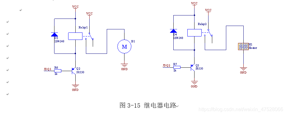
The circuit of the relay module is shown in the figure below (Figure 3-15). The relay is triggered by 5V voltage. Since the relay is turned on to off at the moment, due to the inductive nature of the working coil, an instantaneous voltage spike will be generated at the low voltage end of the relay coil, which can usually be as high as dozens of times the rated operating voltage of the coil. So here put a diode across the relay, because the negative side of the diode is usually connected to VCC, so the voltage spike will be suppressed. The electronic components on the board are protected. When the IO port of the microcontroller gives the PNP transistor a low level, the transistor is turned on and the relay supplies power, so the relay changes from off to on, and finally the small fan or heating film is connected to the 5V voltage, thus realizing the control of the microcontroller. warming or cooling effect.
programming
#include <reg52.h>			// 包含头文件
#include <intrins.h>

#define uchar unsigned char		// 以后unsigned char就可以用uchar代替
#define uint  unsigned int		// 以后unsigned int 就可以用uint 代替

sbit DQ = P1^1;						// DS18B20传感器的引脚定义
sbit w1 = P2^4; 					// 数码管第1位的控制引脚
sbit w2 = P2^5;						// 数码管第2位的控制引脚
sbit w3 = P2^6;						// 数码管第3位的控制引脚
sbit w4 = P2^7;			 			// 数码管第4位的控制引脚
sbit Buzzer  = P1^0;			// 蜂鸣器引脚
sbit JdqLow  = P2^0;			// 温度过低继电器控制(加热)
sbit JdqHig  = P2^1;			// 温度过高继电器控制(降温)
sbit LedLow  = P2^2;			// 温度低指示灯
sbit LedHig  = P2^3;			// 温度高指示灯
sbit KeySet  = P3^2;			// 设置按键
sbit KeyDown = P3^3;			// 减按键
sbit KeyUp   = P3^4;			// 加按键


/*   数码管的显示值:  0    1    2    3    4    5     6   7    8    9    -   */
uchar code Array1[]={ 0x3f,0x06,0x5b,0x4f,0x66,0x6d,0x7d,0x07,0x7f,0x6f,0x40 };

/*                     0.   1.   2.   3.   4.   5.    6.  7.   8.   9.  */
uchar code Array2[]={ 0xBf,0x86,0xdb,0xcf,0xe6,0xed,0xfd,0x87,0xff,0xef };


uchar Buff[4];					// 显示缓冲区
uchar ShowID=1;					// 当前显示的是哪一个数码管

int AlarmLow=150;				// 默认报警的温度下限值是15度
int AlarmHig=300;				// 默认报警的温度上限值是30度


/*********************************************************/
// 毫秒级的延时函数,time是要延时的毫秒数
/*********************************************************/
void DelayMs(uint time)
{
	uint i,j;
	for(i=0;i<time;i++)
		for(j=0;j<112;j++);
}


/*********************************************************/
// 延时15微秒
/*********************************************************/
void Delay15us(void)
{
	_nop_();
	_nop_();
	_nop_();
	_nop_();
	_nop_();
	_nop_();
	_nop_();
	_nop_();
	_nop_();
	_nop_();
	_nop_();
	_nop_();
	_nop_();
	_nop_();
	_nop_();
}


/*********************************************************/
// 复位DS18B20(初始化)
/*********************************************************/
void DS18B20_ReSet(void)
{
	uchar i;
	DQ=0;

	i=240;
	while(--i);

	DQ=1;

	i=30;
	while(--i);

	while(~DQ);

	i=4;
	while(--i);
}


/*********************************************************/
// 向DS18B20写入一个字节
/*********************************************************/
void DS18B20_WriteByte(uchar dat)
{
	uchar j;
	uchar btmp;

	for(j=0;j<8;j++)
	{
		btmp=0x01;
		btmp=btmp<<j;
		btmp=btmp&dat;

		if(btmp>0)		// 写1
		{
			DQ=0;
			Delay15us();
			DQ=1;
			Delay15us();
			Delay15us();
			Delay15us();
			Delay15us();
		}
		else			// 写0
		{
			DQ=0;
			Delay15us();
			Delay15us();
			Delay15us();
			Delay15us();
			DQ=1;
			Delay15us();
		}
	}
}


/*********************************************************/
// 读取温度值
/*********************************************************/
int DS18B20_ReadTemp(void)
{
	uchar j;
	int b,temp=0;

	DS18B20_ReSet();							// 产生复位脉
	DS18B20_WriteByte(0xcc);			// 忽略ROM指令
	DS18B20_WriteByte(0x44);			// 启动温度转换指令

	DS18B20_ReSet();							// 产生复位脉
	DS18B20_WriteByte(0xcc);			// 忽略ROM指令
	DS18B20_WriteByte(0xbe);			// 读取温度指令

	for(j=0;j<16;j++)							// 读取温度数量
	{
		DQ=0;
		_nop_();
		_nop_();
		DQ=1;
		Delay15us();
		b=DQ;
		Delay15us();
		Delay15us();
		Delay15us();
		b=b<<j;
		temp=temp|b;
	}

	temp=temp*0.0625*10;					// 合成温度值并放大10倍

	return (temp);								// 返回检测到的温度值
}


/*********************************************************/
// 定时器初始化
/*********************************************************/
void TimerInit()
{
	TMOD = 0x01;					// 使用定时器0,工作方式1
	TH0  = 248;						// 给定时器0的TH0装初值
	TL0  = 48;						// 给定时器0的TL0装初值
	ET0  = 1;							// 定时器0中断使能
	EA   = 1;							// 打开总中断
	TR0	 = 1;							// 启动定时器0
}


/*********************************************************/
// 显示温度值
/*********************************************************/
void ShowTemp(int dat)
{
	if(dat<0)												// 负号
	{
		Buff[0]=Array1[10];
		dat=0-dat;
	}
	else														// 百位
	{
		Buff[0]=Array1[dat/1000];
	}

	Buff[1]=Array1[dat%1000/100];		// 十位
	Buff[2]=Array2[dat%100/10];			// 个位
	Buff[3]=Array1[dat%10];					// 小数后一位
}


/*********************************************************/
// 报警判断
/*********************************************************/
void AlarmJudge(int dat)
{
	if(dat<AlarmLow)				// 判断温度是否过低
	{
		LedLow=0;							// 温度低指示灯亮
		LedHig=1;							// 温度高指示灯灭
		JdqLow=0;							// 温度过低的继电器闭合(开始加热)
		JdqHig=1;							// 温度过高的继电器断开(停止降温)
		Buzzer=0;							// 蜂鸣器报警
	}
	else if(dat>AlarmHig)		// 判断温度是否过高
	{
		LedLow=1;							// 温度低指示灯灭
		LedHig=0;							// 温度高指示灯亮
		JdqLow=1;							// 温度过低的继电器断开(停止加热)
		JdqHig=0;							// 温度过高的继电器闭合(开始降温)
		Buzzer=0;							// 蜂鸣器报警
	}
	else										// 温度正常
	{
		LedLow=1;							// 温度低指示灯灭
		LedHig=1;							// 温度高指示灯灭
		JdqLow=1;							// 温度过低的继电器断开(停止加热)
		JdqHig=1;							// 温度过高的继电器断开(停止降温)
		Buzzer=1;							// 蜂鸣器停止报警
	}
}


/*********************************************************/
// 按键扫描
/*********************************************************/
void KeyScanf()
{
	if(KeySet==0)									// 如果设置按键被按下
	{
		/* 设置温度下限 */
		LedLow=0;										// 点亮绿色灯(代表当前正在设置温度下限)
		LedHig=1;										// 熄灭红色灯
		Buzzer=1;										// 关闭蜂鸣器
		ShowTemp(AlarmLow);					// 显示温度下限值
		DelayMs(10);								// 延时去抖
		while(!KeySet);							// 等待按键释放
		DelayMs(10);								// 延时去抖

		while(1)
		{
			if(KeyDown==0)								// 如果“减”按键被按下
			{
				if(AlarmLow>-550)						// 判断当前温度下限是否大于-55度
				{
					AlarmLow--;								// 温度下限值减去0.1度
					ShowTemp(AlarmLow);				// 刷新显示改变后的温度下限值
					DelayMs(200);							// 延时
				}
			}

			if(KeyUp==0)									// 如果“加”按键被按下
			{
				if(AlarmLow<1250)						// 判断当前温度下限是否小于125度
				{
					AlarmLow++;								// 温度下限值加上0.1度
					ShowTemp(AlarmLow);				// 刷新显示改变后的温度下限值
					DelayMs(200);							// 延时
				}
			}

			if(KeySet==0)									// 如果“设置”按键被按下
			{
				break;											// 退出温度下限值的设置,准备进入上限值的设置
			}
		}

		/* 设置温度上限 */
		LedLow=1;										// 熄灭绿色灯
		LedHig=0;										// 点亮红色灯(代表当前正在设置温度上限)
		ShowTemp(AlarmHig);					// 显示温度上限值
		DelayMs(10);								// 延时去抖
		while(!KeySet);							// 等待按键释放
		DelayMs(10);								// 延时去抖

		while(1)
		{
			if(KeyDown==0)							// 如果“减”按键被按下
			{
				if(AlarmHig>-550)					// 判断当前温度上限是否大于-55度
				{
					AlarmHig--;							// 温度上限值减去0.1度
					ShowTemp(AlarmHig);			// 刷新显示改变后的温度上限值
					DelayMs(200);						// 延时
				}
			}

			if(KeyUp==0)								// 如果“加”按键被按下
			{
				if(AlarmHig<1250)					// 判断当前温度上限是否小于125度
				{
					AlarmHig++;							// 温度上限值加上0.1度
					ShowTemp(AlarmHig);			// 刷新显示改变后的温度上限值
					DelayMs(200);
				}
			}

			if(KeySet==0)								// 如果“设置”按键被按下
			{
				break;										// 准备退出设置模式
			}
		}

		/* 退出设置模式 */
		LedLow=1;									// 熄灭绿灯
		LedHig=1;									// 熄灭红灯
		DelayMs(10);							// 延时去抖
		while(!KeySet);						// 等待按键释放
		DelayMs(10);							// 延时去抖
	}
}


/*********************************************************/
// 主函数
/*********************************************************/
void main()
{
	int temp;
	uchar i;

	TimerInit();										// 定时器0的初始化(数码管的动态扫描)

	Buff[0]=Array1[0];							// 刚上电显示4个0
	Buff[1]=Array1[0];
	Buff[2]=Array1[0];
	Buff[3]=Array1[0];

	for(i=0;i<8;i++)								// 由于传感器刚上电读出的温度不稳定,因此先进行几次温度的读取并丢弃
	{
		DS18B20_ReadTemp();
		DelayMs(120);
	}

	while(1)
	{
		EA=0;													// 屏蔽中断
		temp=DS18B20_ReadTemp();			// 读取温度值
		EA=1;													// 恢复中断

		ShowTemp(temp);								// 显示温度值

		AlarmJudge(temp);							// 判断是否需要报警

		for(i=0;i<100;i++)						// 延时并进行按键扫描
		{
			KeyScanf();
			DelayMs(10);
		}
	}
}


/*********************************************************/
// 定时器0服务程序
/*********************************************************/
void Timer0(void) interrupt 1
{
	TH0  = 248;				// 给定时器0的TH0装初值
	TL0  = 48;				// 给定时器0的TL0装初值

	P0=0x00;					// 先关闭所有显示
	w1=1;
	w2=1;
	w3=1;
	w4=1;

	if(ShowID==1)  			// 判断是否显示第1位数码管
	{
		w1=0;		   				// 打开第1位数码管的控制开关
		P0=Buff[0];	   		// 第1位数码管显示内容
	}

	if(ShowID==2)  			// 判断是否显示第2位数码管
	{
		w2=0;		   				// 打开第2位数码管的控制开关
		P0=Buff[1];	   		// 第2位数码管显示内容
	}

	if(ShowID==3)  			// 判断是否显示第3位数码管
	{
		w3=0;		   				// 打开第3位数码管的控制开关
		P0=Buff[2];	   		// 第3位数码管显示内容
	}

	if(ShowID==4)  			// 判断是否显示第4位数码管
	{
		w4=0;		   				// 打开第4位数码管的控制开关
		P0=Buff[3];	   		// 第4位数码管显示内容
	}

	ShowID++;	  				// 切换到下一个数码管的显示
	if(ShowID==5)
		ShowID=1;
}
Attachment: http://www.jh-tec.cn/archives/7212
.