[Graduation project] 11-Design of electronic password lock based on single-chip microcomputer (schematic diagram + simulation project + answer essay + answer PPT)
Article Directory
mission statement
Main research content:
Design an electronic combination lock system based on 51 single-chip microcomputer as the main control, matrix keyboard, liquid crystal display and password storage as peripheral circuits, and realize password setting, password modification, correct password unlocking, error prompts, and alarms through programming and other functional requirements.
Research methods:
1. Analyze the structure of the electronic combination lock and determine its functional requirements;
2. Design the hardware and software of the system;
3. Use PROTEUS software to test the function of the electronic combination lock.
Data link
Schematic project files
Schematic screenshots
Simulation project files
Source code project files
Answer essay (low repetition rate), 18046 words
design manual
Summary
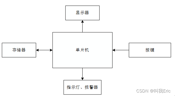
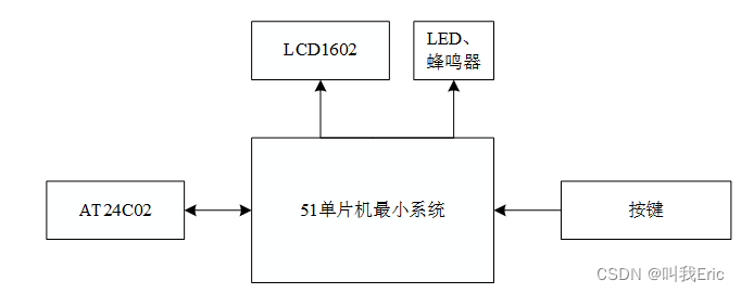
This design is based on the electronic combination lock design of the single-chip microcomputer. The electronic combination lock needs to realize the functions of unlocking, unlocking, and changing the password of the combination lock, and then assists in indicating its status through LED lights and buzzers. It is necessary to use 51 single-chip microcomputer and its peripheral circuits to form a control system. The minimum system of single-chip microcomputer, LCD1602 display, keyboard, AT2402 storage, buzzer and its LED are combined.
Through the analysis of the current development background of the lock, the realization of the system function is determined. Then design the hardware and software of the system. The whole system is a control system application circuit composed of each sub-circuit of the circuit designed in a modular form as a functional module, and finally assembled together. Software design is also to write programs in a modular form, divide software drivers according to functions, and finally call them into the main function. Finally, use the Proteus software to simulate the system, connect the system circuit, and import the program into the single chip for debugging.
Finally, test the system function and system stability, summarize and complete the corresponding functions of the design, and complete this design.
Design framework
Preface 1
Chapter 1 Introduction 2
Section 1 Research Background of Electronic Combination Lock 2
Section 2 Research Status and Trends of Electronic Combination Lock 3
1. Research Status 3
2. Research Trend 3 Section
3 Research Significance of Electronic Combination Lock
4 The main research content of the four sections 4
Chapter 2 Design scheme of electronic combination lock 6
Section 1 System design function analysis 6
Section 2 System structure of electronic combination lock 6
Section 3 Summary of this chapter 7
Chapter 3 Hardware of electronic combination lock Design 8
Section 1 MCU Minimum System 8
Section 2 Matrix Button Circuit 9
Section 3 AT24C02 Circuit 10
Section 4 LCD1602 Display Circuit 11
Section 5 Buzzer and LED Circuit 12
Section 6 Power Circuit 13
Section 7 System General circuit 13
Section 8 Summary of this chapter 14
Chapter 4 System software design 15 Section
1 Introduction to programming software 15 Section
2 Main program design 15
1. Main program design process 15
2. Main program source code 17
Section 3 AT24C02 program Design 17
1. AT24C02 Program Flow Design 17
2. AT24C02 Program 18
Section 4 Matrix Keyboard Program Design 19
1. Program Flow Chart of Keyboard Input Block 19
2. Matrix keyboard program 20
Section 5 Buzzer alarm and LED program design 22
1. Alarm and display lamp program design process 22
2. Buzzer alarm and LED program source code 23
Section 6 LCD1602 display program design 24
1 , LCD1602 display program design process 24
2. LCD1602 program source code 24
Section 7 Summary of this chapter 25 Chapter 5
System Simulation 27 Section 1
Introduction of Simulation Software 27
Section 2 System Simulation 28
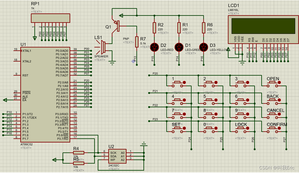
1. Simulation Circuit Construction 28
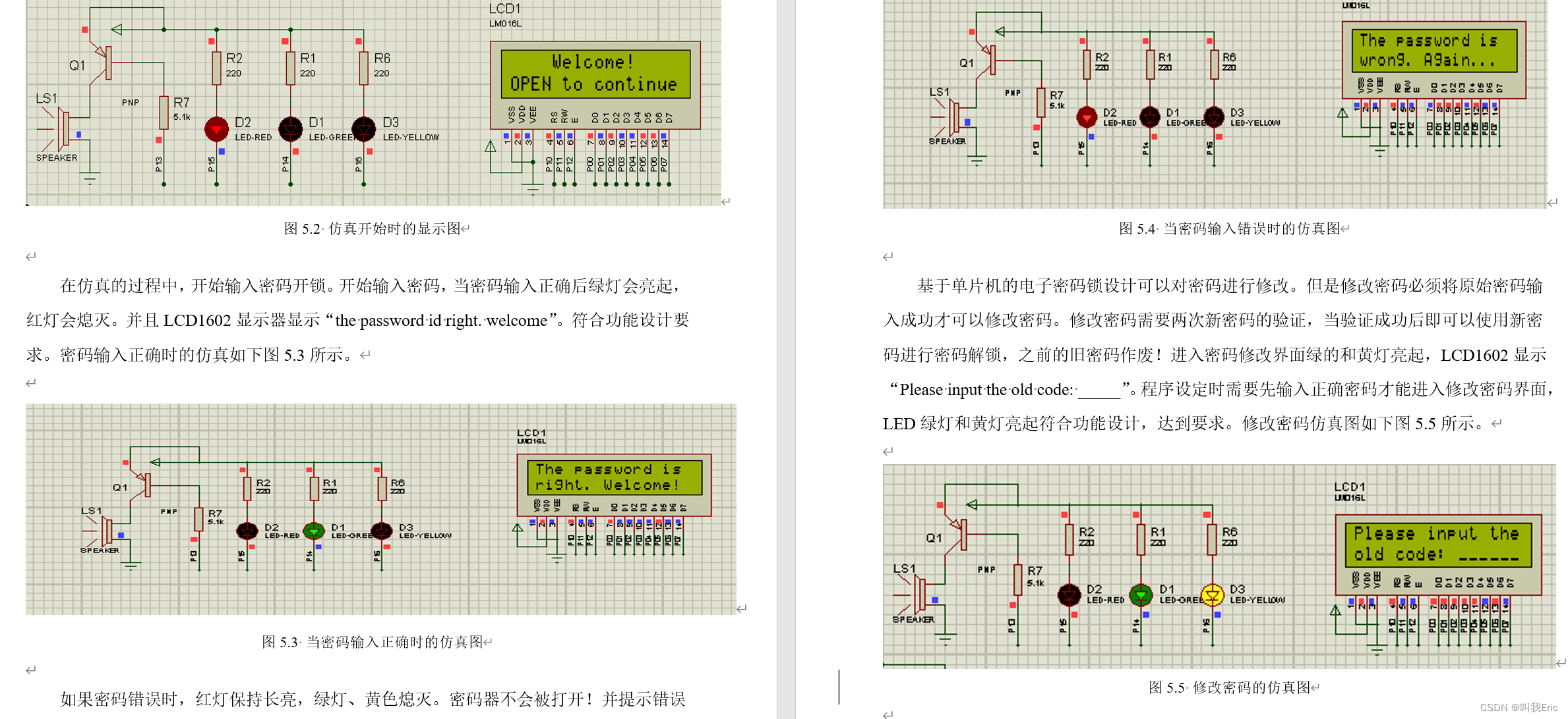
2. Functional Simulation 28
Section 3 Summary of this chapter 31
Conclusion 33
Acknowledgments 34
References 35 Appendix
36
1. English original text 36
2. English translation 39
3. Source code 42
Design instructions and design documents
Source code display
//退格
void password_back_answer()
{
	if(j>=0)
	{
		if(j==0)
		{
			password_save[0]=0;
		}
		else
		{
			password_save[--j]=0;
			lcd_wchar(1,10+j,'_');
		}
	}
}

//取消
void password_cancel_answer()
{
	uchar i;
	lcd_wstr(1,10,"______");
	for(i=0;i<j;i++)
	{
		password_save[i]=0;
	}
	j=0;
}

//密码正确
void succeed_answer()
{
	led_green=0;
	led_red=1;
	confirm_flag=0;
	fail_times=0;
	lcd_wcmd(0x01);
	lcd_wstr(0,0,"The password is");
	lcd_wstr(1,0,"right. Welcome!");
	lcd_delay(3000);
}

//密码错误,蜂鸣器报警
void fail_alarm()
{
	uint i;
	for(i=0;i<2000;i++)
	{
		DelayMs(1);
		beep=~beep;
	}
}
//密码错误
void fail_answer()
{
	fail_times++;
	led_red=0;
	if(fail_times==3)
	{
		fail_times=0;
		lcd_wcmd(0x01);
		lcd_wstr(0,0,"The password is");
		lcd_wstr(1,0,"wrong. Sorry!");
		fail_alarm();
		lcd_delay(3000);
		input_admin_password();
		ReadFromROM(read_password,6,6);
		password_confirm();
		if(confirm_flag)
		{
			led_green=0;
			led_red=1;
			confirm_flag=0;
			lcd_wcmd(0x01);
			lcd_wstr(0,0,"The adm code is");
			lcd_wstr(1,0,"wright. Welcome!");
			lcd_delay(3000);
			lcd_wcmd(0x01);
			lcd_wstr(0,1,"Do you want to");
			lcd_wstr(1,1,"show the code?");
			key=16;
			while((key!=confirm)&&(key!=password_cancel))
			{
				keydown();
			}
			if(key==confirm)
			{
				display_password();
				lcd_delay(6000);
				function_choose();
			}
			else
			{
				function_choose();
			}
		}
		else
		{
			lcd_wcmd(0x01);
			lcd_wstr(0,0,"The adm code is");
			lcd_wstr(1,0,"wrong. Sorry!...");
			fail_alarm();
			lcd_delay(3000);
			lcd_wcmd(0x01);
			lcd_wstr(0,0,"Lock is locked!!");
			lcd_wchar(1,2,':');
			lcd_wchar(1,5,':');
			lcd_wstr(1,9,"......");
			EA=1;
			while(count_second!=1)
			{
				display_initial_time();
			}
			count_second=0;
			lock_flag=1;
			while(lock_flag)
			{
				display_lock_time();
			}
			system_start();
		}
	}
	else
	{
		lcd_wcmd(0x01);
		lcd_wstr(0,0,"The password is");
		lcd_wstr(1,0,"wrong. Again...");
		lcd_delay(3000);
		input_password();
		ReadFromROM(read_password,0,6);
		password_confirm();
		if(confirm_flag)
		{
			succeed_answer();
			function_choose();
		}
		else
		{
			fail_answer();
		}
	}
}