Introduction to Computer Networks in Soft Design
-
- First, the basic composition of the computer
- 3. Basic units and bases of computers
- 4. Original code inverse code complement code shift code
- 5. Floating point numbers
- 6. Addressing
- Seven, check code
- 8. RISC and CISC
- 9. Assembly line
- 10. Storage
- 11. Cache
- 12. Interruption
- 13. Input and output (I/O) control mode
- 14. Bus (problem, miscellaneous, low score)
- 15. Encryption technology and authentication technology
- 16. Encryption algorithm
- 17. Reliability Technology
- 1. Logical and, or, same or, exclusive or
- 18. Miscellaneous knowledge points
First, the basic composition of the computer
1. Computer composition logic diagram
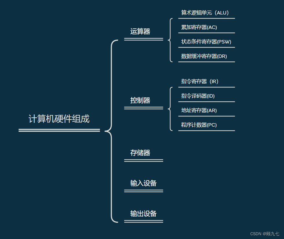
2. Function of computer components
(1) The role of primary components
- Arithmetic unit: the execution unit of a computer, controlled by a controller, to perform arithmetic or logic operations
- Controller: Determines the automation of computer processes. It can not only ensure the correct execution of program instructions, but also handle abnormal events.
- Memory: memory device, divided into internal memory and external memory
- Input devices, output devices: called peripherals
(2) Function of secondary components
-
Arithmetic Logic Unit (ALU): Performs arithmetic or logic operations, including addition, subtraction, multiplication, division, and, or not
-
Accumulation Register (AC): Provides the work area for the ALU when the ALU performs arithmetic or logic operations. Provide operation data or temporarily store operation results.
-
Status condition register (PSW): Save various result status codes of arithmetic instructions and logic instruction operations or tests. Such as: operation result carry flag, operation result is 0 flag, etc.
-
Data Buffer Register (DR): The transfer station and buffer for data and instructions between the cpu, memory and peripherals. Saves an instruction or a word of data when reading or writing to memory
-
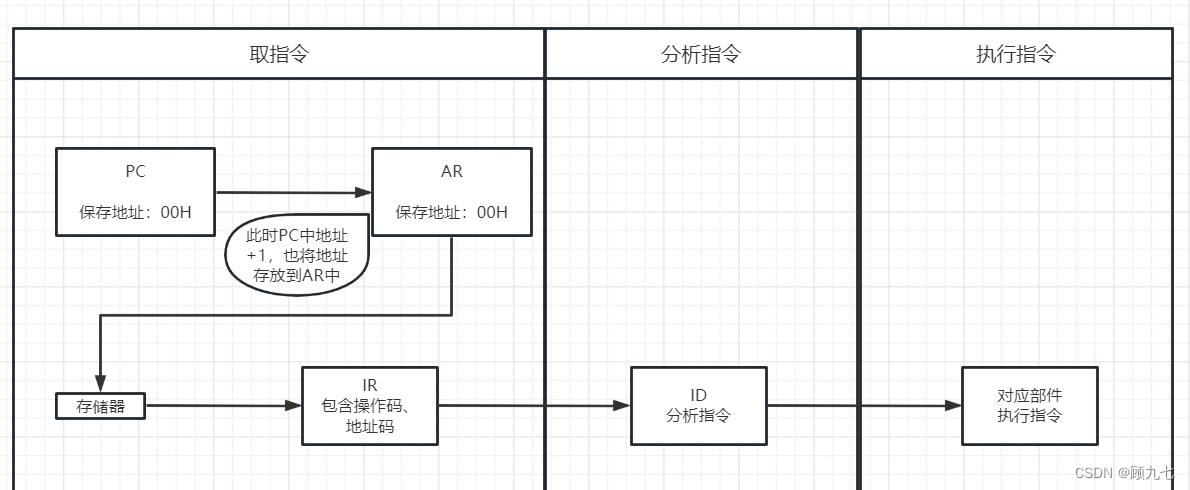
Instruction register (IR): When the cpu executes an instruction, it is taken from the memory and placed in the buffer register, and then temporarily stored in the instruction register. The instruction decoder generates instructions based on the contents to control the work of other components. not accessible
-
Instruction Decoder (ID): An instruction consists of an opcode and an address code. The instruction decoder analyzes the operation code, generates corresponding instructions, and controls the work of other components
-
Address register (AR): When executing an instruction, due to the difference in memory and cpu execution speed, the address information needs to be saved until the instruction is completed
-
Program counter (PC): It has two functions of registering information and counting. The execution mode is divided into sequential execution and transfer execution. When the program is executed, the address of the instruction is saved in the PC, and it cannot be determined until it is loaded into the memory. Therefore, the content of the pc is the address of the first instruction. During execution, the cpu modifies the content of the pc to ensure that the content stored in the pc is The address of the instruction to be executed , which is executed sequentially. Transfer execution, the CPU directly modifies the transfer address given by the transfer instruction, or modifies it according to the displacement
Two, CPU
1. CPU composition
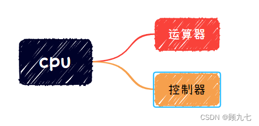
2. CPU function
- program control
- time control
- Operation control: The CPU generates an operation signal for each instruction and transmits the operation signal to the corresponding operation unit, and controls the corresponding unit to operate according to the requirements of the instruction.
- data processing
3. Basic units and bases of computers
1. The basic unit of the computer (space size from small to large)
- bit b bit
- Byte B Byte 1B = 8b
- Kilobyte KB 1KB = 1024B
- megabyte MB 1MB = 1024KB
- Gigabyte GB 1GB = 1024MB
- Terabyte TB 1TB = 1024GB
Minimum data unit: b
Minimum storage unit: B
2. Base and base conversion
(1) Hexadecimal representation
- Binary (B) value is composed of 0 and 1, every binary into one
- The octal (O) value is composed of 0 to 7, every eight into one
- Decimal (D) is the commonly used representation. The value is composed of 0 to 9, every decimal
- The hexadecimal (H) value is represented by 0~9 and A/B/C/D/E/F, and the letters represent 10/11/12/13/14/15, every hexadecimal
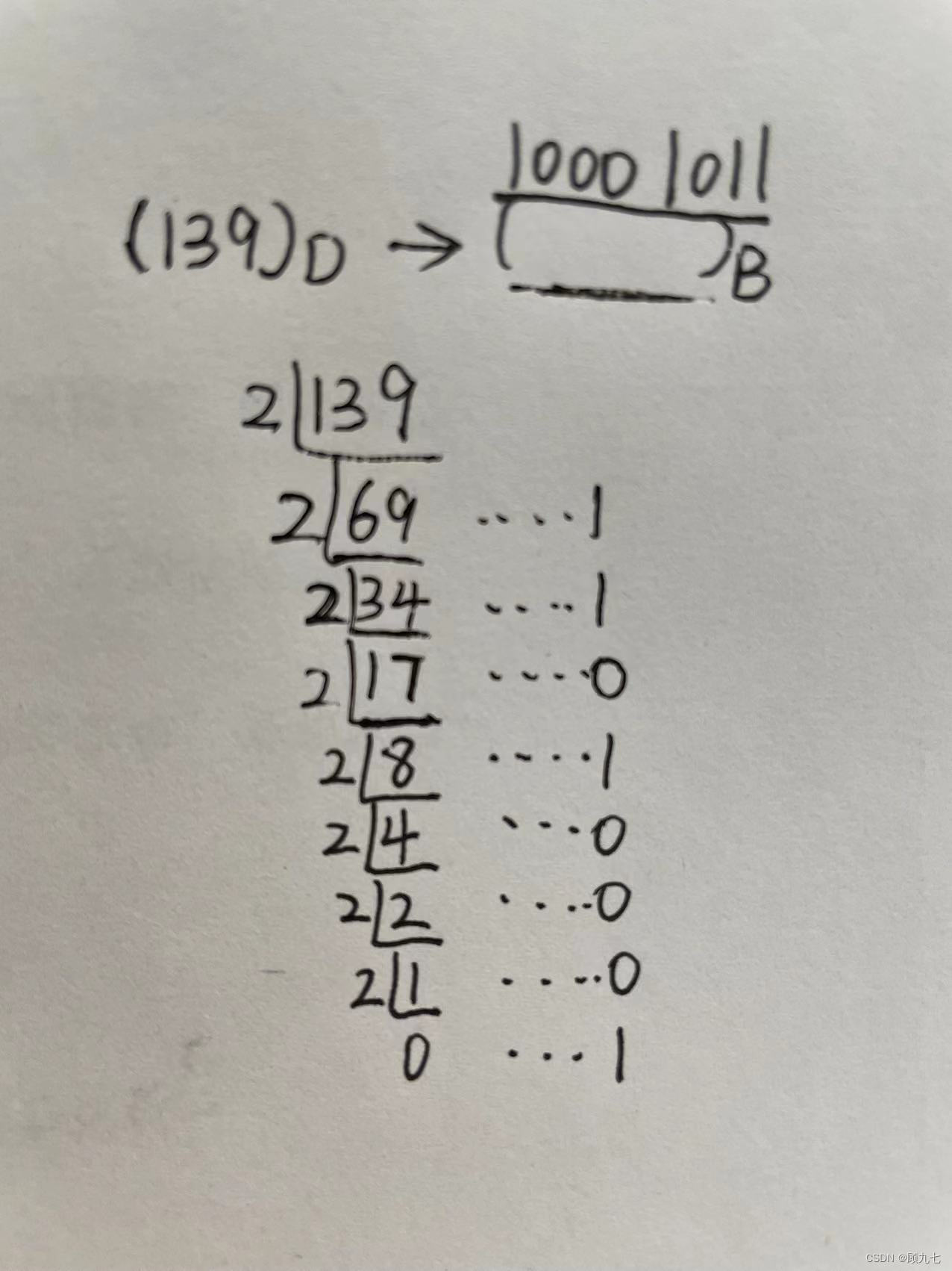
(2) Binary conversion
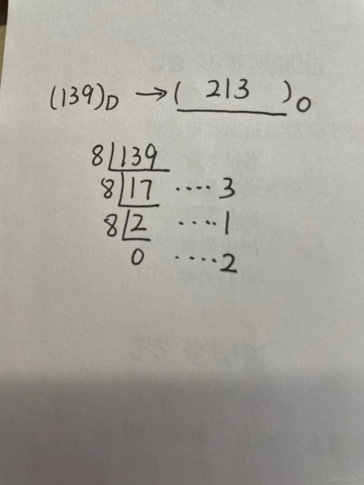
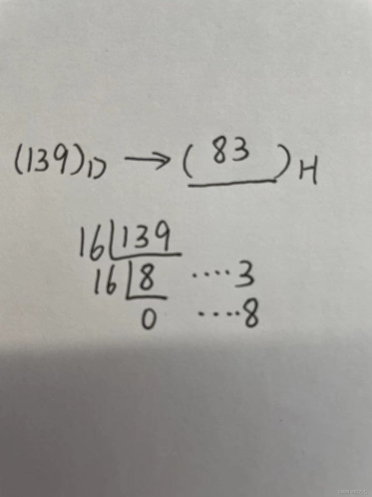
Decimal to R base
In the method of dividing R and taking the remainder
, the D number is used as the dividend, and R is used as the divisor. Keep dividing until the quotient is 0, take out the remainder and arrange it from bottom to top
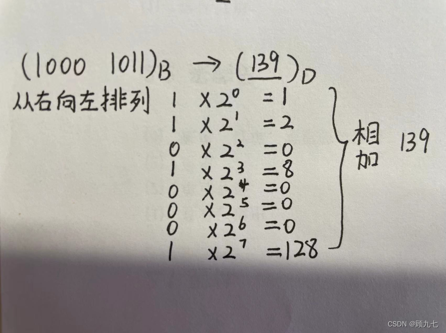
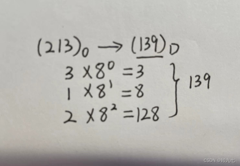
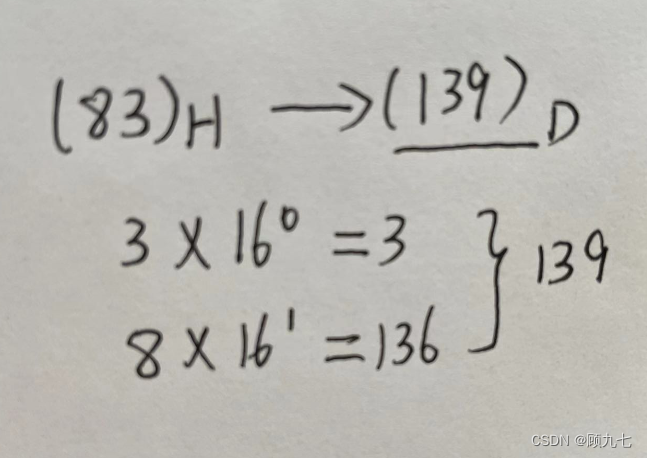
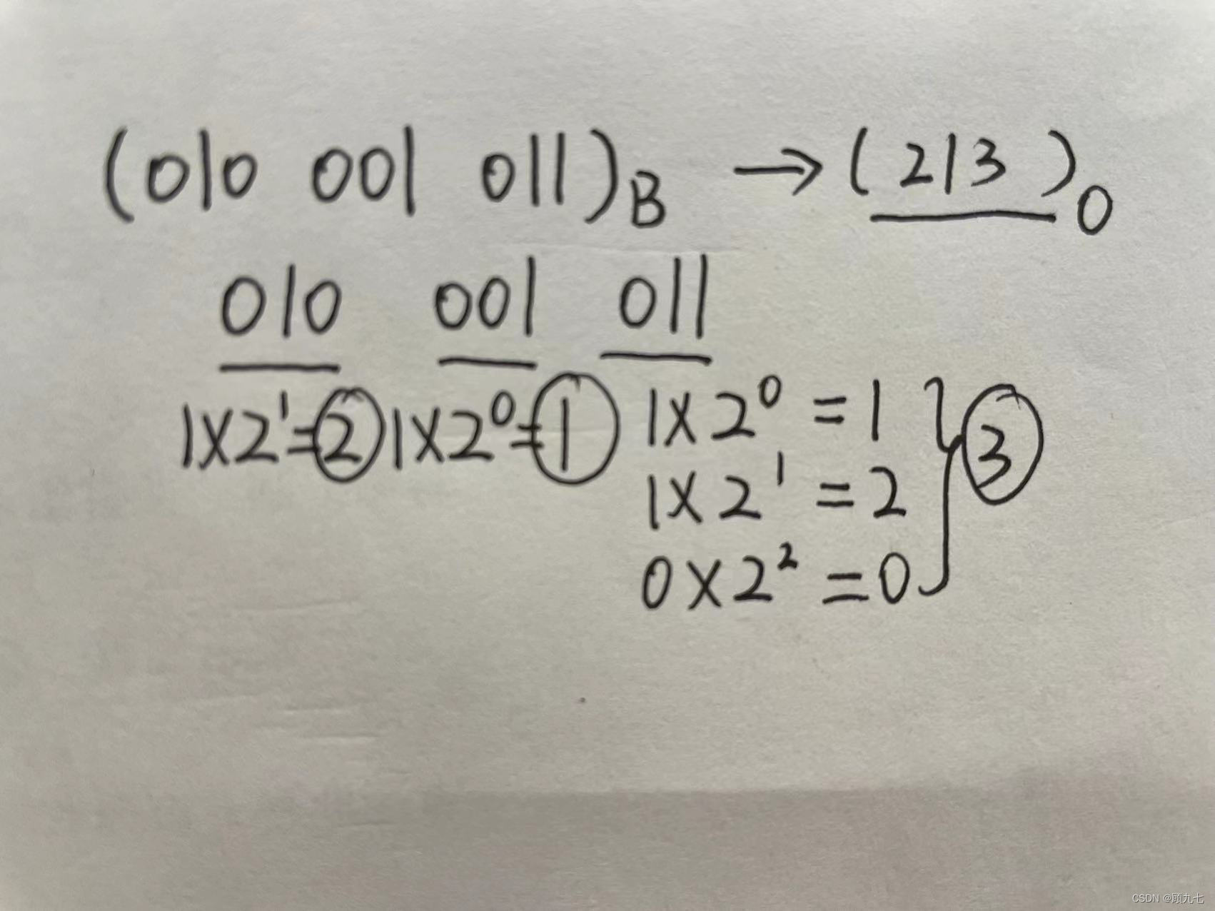
R base to decimal
According to the weight expansion and summation,
the R base numbers are from left to right, and each digit is multiplied by the index-1 of R.
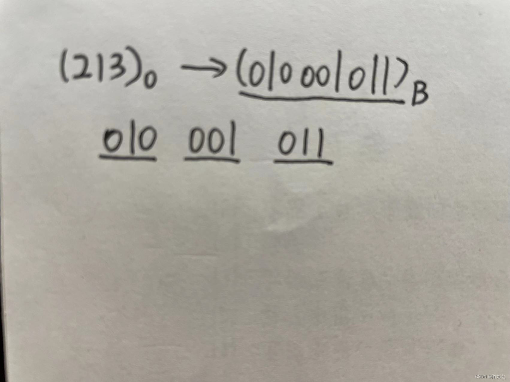
binary to octal
A three-digit binary number can represent an octal number, because 2 to the third power is 8, and the octal representation is composed of 0~7
Octal to Binary
binary to hexadecimal
Four binary numbers can represent a hexadecimal number, because the 4th power of 2 is 16, and the maximum hexadecimal number is 15
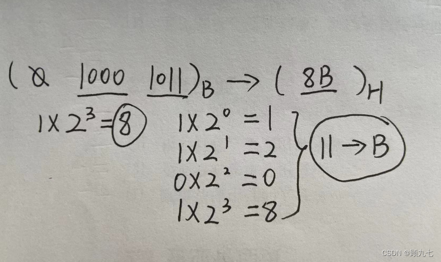
hexadecimal to binary
Other base and binary calculations
When other base numbers do not correspond well to binary, the value of the power of 2 can be written aside and calculated by addition.
4. Original code inverse code complement code shift code
The representation of various values in the computer is called machine number, which adopts the binary counting system. The symbols are represented by 0 and 1, 0 represents positive numbers, and 1 represents negative numbers.
Machine numbers are divided into unsigned numbers and signed numbers. Unsigned numbers are positive numbers, and signed numbers are negative numbers. The highest bit of the machine number represents positive or negative
1. Original code
In the original code notation, the highest bit is the sign bit, and the value after the sign bit is called the absolute value of the value.
0 has two forms in the original code: +0 = 0000 0000, -0 = 1000 0000
2. Inverse code
Inverse code of unsigned number: the same as the original code, no change. Inverse
code of signed number: the sign bit remains unchanged, and the absolute value is reversed bit by bit
3. Complement code
Inverse code of unsigned number: the same as the original code, no change.
Inverse code of signed number: add 1 to the end of the inverse code.
Complement code feature: complement code and take complement code = original code
In two's complement representation, 0 has a unique representation: +0's complement = 0000 0000 , -0's complement = 0000 0000
4. Frame shift
Regardless of signed or unsigned numbers, invert the sign bit of the two's complement
5. Floating point numbers
1. The reason
When the machine word length is n, the complement code and shift code of fixed-point numbers can represent 2 n numbers, and the original code and inverse code can only represent 2 n -1 numbers. Indicates that the range is small, so a floating point number is produced. Floating-point numbers are numbers with an unfixed decimal point position, which can represent a larger range
2. Nature
In the world of decimal, 2782.3527 = 0.27823527 10 4
Similarly, in the world of binary, 11001010.01 = 1100.101001 2 4
Definition of floating-point number: Binary number N can also be expressed as N=2 E *F, where E is called the order code, F called the mantissa. The number represented by the exponent and the mantissa is a floating point number. This method of representing numbers is called floating-point notation.
-
The number expressed in floating point notation, the exponent code is a signed integer, and the mantissa is a signed pure decimal (a pure decimal refers to a decimal whose integer bit is 0)
-
The representation format is as follows: step symbol | step code | number symbol | number
-
The representation range of floating-point numbers is determined by the order code, and the numerical precision of the representation is determined by the mantissa
-
If the exponent code of the floating-point number (including one-order symbol) is represented by R-bit shift code, and the mantissa (including one-digit symbol) is represented by M-bit complement code, then the value range that this floating-point number can represent is:
Largest positive number: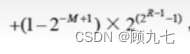
Smallest negative number:

3. Normalized floating point numbers
Normalization is to limit the absolute value of the mantissa of the floating-point number between [0.5, 1]
6. Addressing
The important addressing methods are arranged according to the calculation speed (the access speed of general-purpose registers inside the CPU is faster than that in memory)
- Immediate addressing , the operand is in the instruction
- Register addressing , the operand is stored in the register, and the name of the register where the operand is located is given in the instruction
- Direct addressing , get the memory address of the operand from the memory, the address of the operand in the instruction
- Register indirect addressing , the operand is stored in a memory unit, and the memory address is stored in a register
- Indirect addressing , where the address of the operand address is given in the instruction.
- relative addressing
- indexed addressing
In the industry standard IEEE754 floating-point number format, the code shift is used for decoding, and the mantissa is represented by the original code
Seven, check code
1. Function
Detect if an error occurred during data transmission
2. Features
- The code distance is 2, which can detect errors
- The code distance is greater than or equal to 3, error detection is possible, and error correction is possible
3. Parity check code
Make the number of 1s odd (odd parity) or even (even parity) by adding a bit to the code
- Code distance is 2, error detection is possible
- Divided into odd parity and even parity
- For odd parity, only an odd number of data bit errors can be detected
- There are three commonly used parity codes: horizontal parity code, vertical parity code, horizontal and vertical parity code
4. Hamming Code
Insert k check codes at specific positions between data bits, and realize error detection and error correction by expanding the code distance
18. The code distance is at least 3, which can detect errors and possibly correct them
19. n represents the number of data bits , k represents the number of parity bits. The format of the Hamming code must be guaranteed: 2 k -1 >= n+k
5. Cyclic redundancy check code
Use the generator polynomial to generate r check digits for k data bits for encoding, and the encoding length is k+r
20. The code distance is 2, which can detect errors
21. The code format is k data bits followed by r check digits
22 . When calculating the cyclic redundancy check code, the modulo 2 operation is used
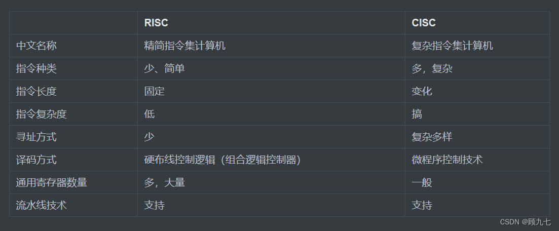
8. RISC and CISC
9. Assembly line
That is, the pipeline processing of instructions. Assuming that the instruction processing goes through three steps of fetching instructions, calculating, and outputting results, the three steps are respectively recorded as F/C/O, and the time spent is 0.2s, 0.4s, and 0.1s respectively.
There are times T1, T2, T3, T4, T5...Tn
T1: F1 (fetch the first instruction)
T2: F2 (fetch the second instruction), C1 (calculate the first instruction)
T3: F3, C2, O1 ( output the result of the first instruction)
T4: F4, C3, O2
...
1. Common concepts
- The formula for calculating the execution time of n instructions in the pipeline: the execution time of the first instruction + (n-1) * the longest period of time during the execution of the instruction
- Throughput: The reciprocal of the longest period. If the throughput rate of n instructions is n/execution time
- Speedup ratio = time of pipeline execution / time of sequential execution
- Operating cycle: maximum time period
2. Nature
- To maximize speedup and efficiency, the same time should be used for all stages of the pipeline
- Pipelining with asynchronous processing does not improve performance
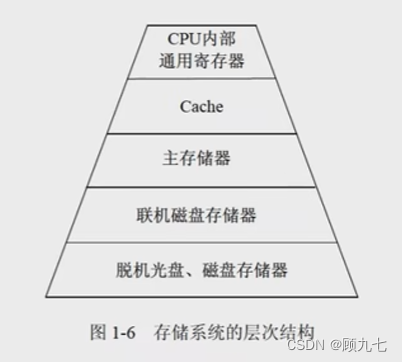
10. Storage
cache: SRAM
Main memory: DRAM, periodically refreshed, guaranteed data
1. Classification of memory
- Classified by location:
- Memory: fast, small capacity
- External storage: slow speed, large capacity
- Classified by constituent materials:
- magnetic storage
- Semiconductor memory: static memory (SRAM), dynamic memory (DRAM)
- optical storage
- Classified by working method:
- Read/Write Memory RAM
- ROM
- Fixed ROM
- Programmable Read Only Memory PROM
- Erasable Programmable Read-Only Memory EPROM
- Electrically Erase Programmable Read-Only Memory EEPROM
- Flash memory is stored in blocks and deleted in blocks . U disk. After a power outage, no data will be lost . Can replace ROM, not main memory
- Classified by access method:
- access by address
- Access by content
- Classified by addressing mode:
- RAM
- sequential memory SAM
- DAM
2. Knowledge points
- Associative memory: is a memory accessed by content
- Virtual memory: consists of main memory and auxiliary memory
- Spatial locality : After the CPU accesses x02, it may access x01 or x03, the space
- Time locality : After the CPU accesses x02, it may access x02 again in a short time
11. Cache
1. Reasons in this world
As a transit between CPU and memory. Since the CPU is super fast and the memory is only fast, CPU energy consumption will occur when accessing data, so there is a cache that is 5 to 10 times faster than the memory. But the cache is transparent to programmers (the transparency mentioned here means that it cannot be seen at all)
2. CPU/cache/memory
The cache is used to store the currently most active programs and data. If it is not saved in the cache, back up a copy of the data taken from the memory to the cache; if it already exists in the cache, directly fetch the data in the cache.
3. Replacement algorithm
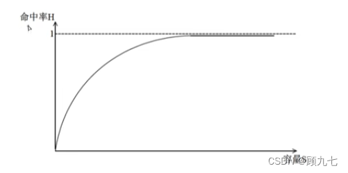
When the cache does not have enough storage space to store new active programs or data, it is necessary to use a replacement algorithm to replace the existing data. Its goal is to make the cache obtain the highest possible hit rate.
The size of the cache capacity determines the hit rate. The higher
the capacity, the greater the hit rate. It should be noted here that it does not always increase linearly;
however, the higher the capacity and the higher the hit rate, the longer the hit time, which is proportional.
Common replacement algorithms:
- random replacement algorithm
- first in first out algorithm
- Least Recently Used Algorithm
- Optimal Replacement Algorithm
4. Address mapping method
When it comes to the replacement algorithm, let's talk about how the cache saves the data in the memory.
When the CPU is working, what is sent is the address of the main memory unit, and information should be read and written from the cache memory. At this time, the memory address needs to be converted into a cache memory address. This conversion of addresses is called address mapping.
-
Direct image: The corresponding relationship between the blocks of the main memory and the blocks of the cache is fixed (the conflict is large ) . Put it in the 0th block of the cache
-
Fully associative image: memory and cache memory are divided into blocks of the same size, allowing any block of memory to be transferred to any block of cache ( small conflicts )
-
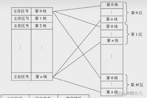
Group associative image: ( less conflicts )
The cache is first divided into "groups", and then divided into "blocks". The memory is
first divided into "areas", then "groups", and then "blocks".
It will correspond to the 0th group of the cache, and the blocks in the memory group are "full associative images" for the blocks in the cache, which can correspond to the 0th block and also correspond to the mapping between the first block cache and the main memory
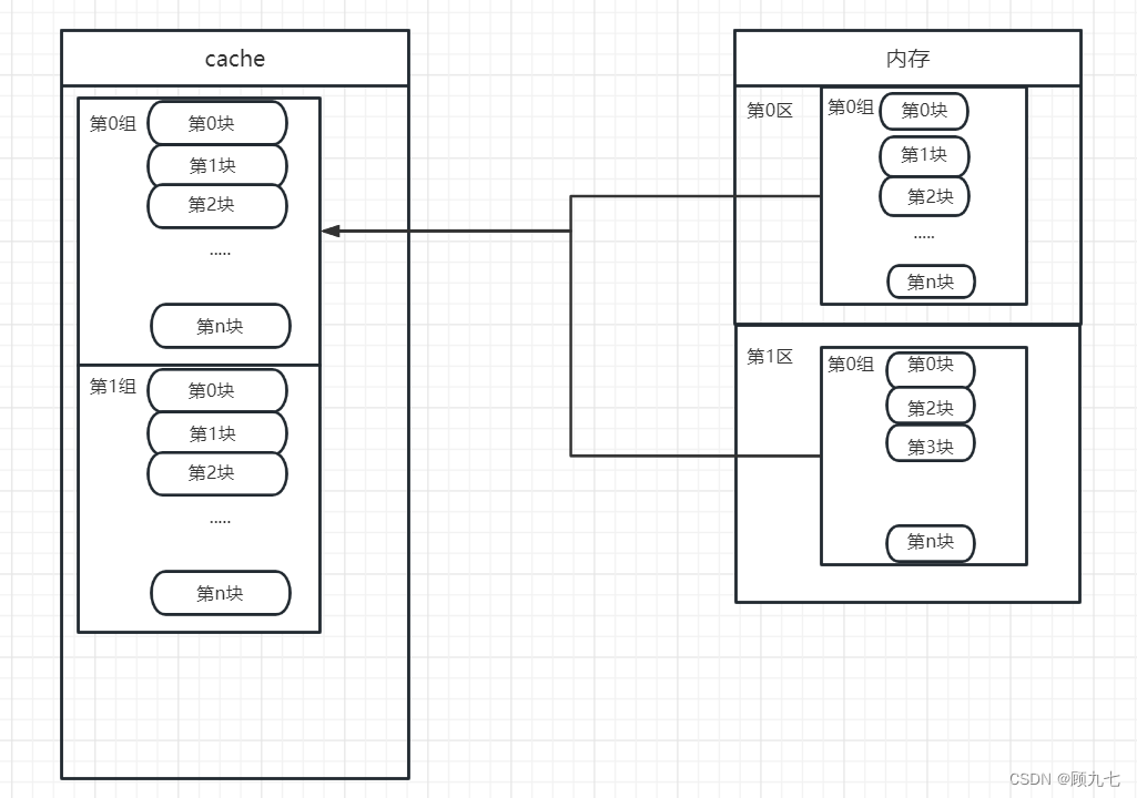
address is done automatically by the hardware
12. Interruption
When a computer encounters an event that needs to be dealt with urgently during program execution, it suspends the currently executing program, turns to execute the relevant service program, and automatically returns to the source program after processing. This process is called interruption.
1. Knowledge points
- Interrupt vector: Each interrupt vector corresponds to an interrupt service program entry address. When there are many interrupt programs, in order to improve the response speed of interrupt response, the interrupt vectors are collected into an interrupt vector table
- Interrupt response time: from issuing an interrupt response to entering the interrupt service routine
- Save the scene: that is, ctrl+s when the schedule life is interrupted. The purpose is to correctly return to the interrupted program to continue execution
- In order to facilitate the realization of multi-level interrupt nesting, it is most effective to use the stack to protect the breakpoint and the scene (first in, last out)
- The interrupt request issued by the I/O device is a maskable interrupt, and the power failure is a non-maskable interrupt
- An exception is a special event that occurs inside the processor during the execution of an instruction, such as "divisor of a division operation is 0"; an interrupt is a request from outside the processor, such as "DMA transmission ends"
13. Input and output (I/O) control mode
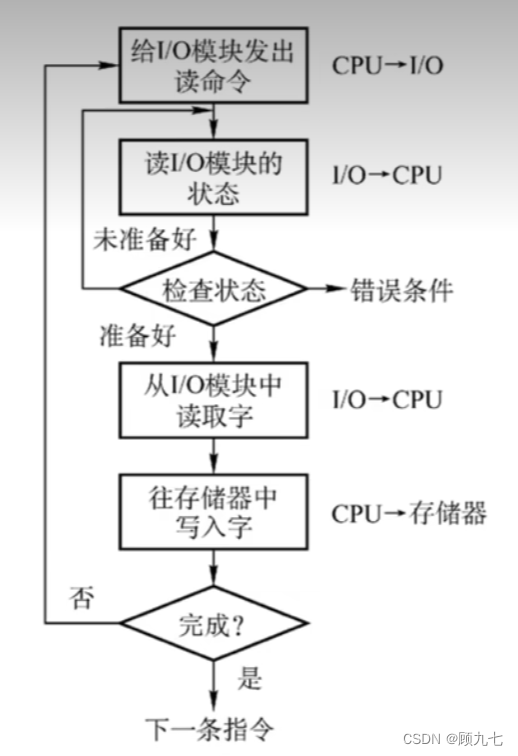
1. Program query method
- The CPU and I/O devices work serially, which leads to low CPU utilization
- Data needs to be kept in memory by the CPU
- Only read/write one word at a time
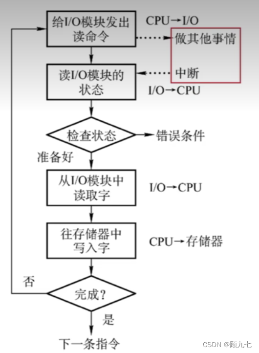
2. Interrupt-driven mode
- CPU and I/O devices can work in parallel
- Requires CPU to keep data in memory
- I/O devices actively report execution completion to the CPU through interrupts
3. Direct storage method DMA
- CPU and I/O devices work in parallel
- No need for CPU participation in the process of data transmission
- Store data directly in memory by peripherals
- The unit of one read and write is block, not word
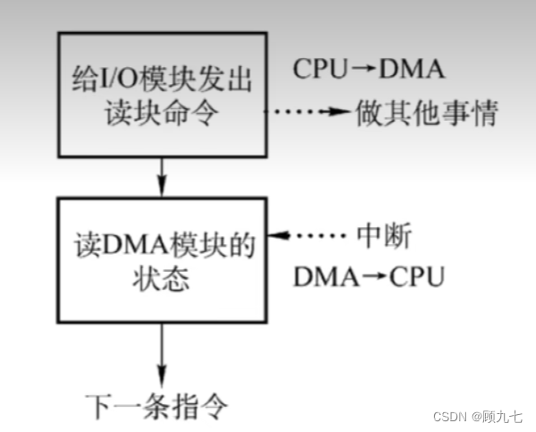
4. Only the knowledge points that you understand
- The resource occupied by the DMA operation is the system bus, and the CPU responds to the DMA request at the end of a bus cycle
- When using DMA to transfer data, each data transfer requires a storage cycle
14. Bus (problem, miscellaneous, low score)
In the computer system, the bus structure is adopted to facilitate the building block structure of the system and reduce the number of information transmission lines.
1. Classification
- Data Bus
- address bus
- control bus
2. Common buses
- ISA bus
- EISA bus
- PCI bus: internal bus for parallel transmission
- PCI Express bus
- front side bus
- RS-232C
- SCSI bus: parallel transfer external bus
- SATA
- USB
- IEEE-1394
- IEEE-488 bus
15. Encryption technology and authentication technology
Common computer network security threats include eavesdropping, tampering, counterfeiting, and denial
1. Encryption technology
The corresponding solution to eavesdropping is encryption technology. Encryption prevents adversary passive attacks
(1) Common encryption techniques
Symmetric encryption (shared key encryption)
During the data transmission process between person A and person B, A uses a symmetric encryption key to encrypt the content to be transmitted, and B needs to obtain the same key to decrypt the transmission content.
Only one key exists
Cons: Key distribution is problematic. After the ciphertext is transmitted to B, the way to transmit the key to B requires plaintext.
Advantages: fast decryption and encryption; suitable for encrypting a large amount of plaintext data
Asymmetric encryption (public key system, public key system)
Person A and Person B each have a public key and a private key, and the public key is known to everyone. When A transmits data to B, it first encrypts with B's public key, and after B obtains the ciphertext, it decrypts it with its own private key, and vice versa.
There is no connection between the public key and the private key, and the corresponding public key or private key cannot be inferred.
Advantages: no problem with key distribution Disadvantages
: slow decryption and encryption; not suitable for encrypting a large amount of plaintext data
2. Authentication technology
The solution technology corresponding to tampering is digest; the solution technology corresponding to counterfeiting and denial is digital signature. Authentication prevents active attacks by adversaries
(1) Common authentication techniques
Summary
When person A sends information to B, the cipher text carries the digest generated by using the hash algorithm plain text AH.
After receiving it, B decrypts the cipher text to generate plain text, and uses the hash algorithm to process the plain text BH again. The two summaries are compared. If the comparison is the same, it has not been tampered with; otherwise, it has been tampered with.
digital signature
A adds the ciphertext that encrypts the digest with its own private key to the ciphertext, and
B decrypts the entire ciphertext after obtaining it, and then uses A's public key to decrypt the digest ciphertext again (here you can determine whether A sent message), and then decrypt the content ciphertext.
After performing hash algorithm processing on the content plaintext, compare it. It can be determined whether the content has been tampered with.
Sign (encrypt) with the sender's private key and decrypt with the sender's public key
digital certificate
The purpose is to prevent person C with ulterior motives from replacing his own public key given by A to B with C's public key during the transmission of public key information between person A and person B. In this way, even if digest and digital signature technologies are used, " Counterfeit" situation, so the introduction of third-party participation - digital certificates.
This technology is only for asymmetric encryption, and the CA organization has its own private key and public key. Person A applies for a digital certificate from the CA organization, sends the basic information of person A and A's public key to the CA organization, and the CA organization uses its own private key to encrypt (sign). After obtaining the ciphertext, person B obtains A's digital certificate from the CA organization, and uses the public key of the CA organization to decrypt and obtain A's public key to decrypt A's ciphertext. In this way, even if C tampers with the public key of A sent by A to B, it does not matter, and B will not use the public key sent by A at all.
16. Encryption algorithm
1. Common symmetric encryption algorithms
- OF THE
- 3DES
- IDEA
- RC-5
- AES: block encryption algorithm
- RC4
2. Common asymmetric encryption algorithms
- RSA
- ECC
- DSA
3、MD5
- is a digest algorithm
- The length of the result calculated for an input of any length is 128 bits
17. Reliability Technology
R1, R2, R3...represent the reliability of components. Reliability calculation formula of series
system : R= R1 R2 R3*...Rn
**Parallel system (redundant system)** Reliability calculation formula: R= 1-(1-R1 )(1-R2)(1-R3)...(1-Rn)
1. Logical and, or, same or, exclusive or
true is 1, false is 0
(1) Logical AND &
0&0 = 0
1&0 = 0
0&1 = 0
1&1 = 1
(2) logical or ||
0 || 0 = 0
1 || 0 = 1
0 || 1 = 1
1 || 1 = 1
(3) Logical OR
Same as 1, different as 0
(4) Logical XOR
Same as 0, different as 1
18. Miscellaneous knowledge points
- Active attacks: replay, IP address spoofing, denial of service, system interference, modifying data commands
- Passive attack: traffic analysis, session interception
- Arithmetic left shift is equivalent to multiplying the operand by 2