Article directory
foreword
In the previous article, I introduced all the registers related to GPIO, and at the end simply realized the control of an LED light. Since the space is too long, the programming part is a bit sloppy. Let’s make a slightly more detailed description of the small LED lights below, which will involve some common bugs in the use of the development environment and some C language knowledge related to bit operations. If there are deficiencies in the article, you are welcome to criticize and correct. It is not easy to create. If you need to reprint or quote, please indicate the source.
GPIO general output mode
The common off-chip peripherals that use the general output mode are LED lights, active buzzers, relays, etc. The most common ones on our board are LED lights. In the previous article, port A No. 4 with GPIO is configured The pin is in push-pull output mode, and outputs a low level to light up the LED light. Let's review the configuration process first.
Initialize the GPIO of the LED light
The first is the initialization part, here is still a pseudo-code, which looks more intuitive:
//注意前面这一段注释一定要记得写上,一方面是为了方便自己能够看懂自己的代码,另一方面,当别人看你的代码的时候也能一目了然。
/*******************************
函数名:Led_Init
函数功能:LED灯IO口初始化配置
函数形参:void
函数返回值:void
备注:
LED1----->PA6 通用输出
LED2----->PA7 通用输出
********************************/
void Led_Init(void)//函数命名,一般是'模块——功能'其中模块名与功能名的首字母大写
{


	①打开PA的时钟
	②端口模式寄存器
	③输出类型寄存器
	④输出速度寄存器
	⑤上下拉寄存器
}
According to this pseudo code, we can configure the mode of the corresponding pin of the corresponding port as the general output mode.
Next, let's configure it again on the basis of yesterday, and initialize both LEDs together this time.
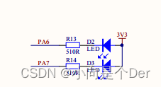
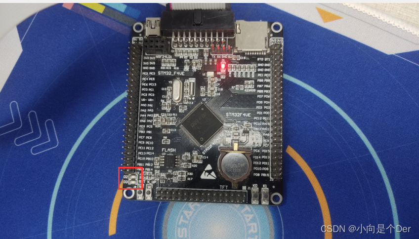
schematic diagram
It's still yesterday's schematic diagram. From this, we can know that the two ports PA6 and PA7 need to be configured.
initialization code
/*******************************
函数名:Led_Init
函数功能:LED灯IO口初始化配置
函数形参:void
函数返回值:void
备注:
LED1----->PA6 通用输出
LED2----->PA7 通用输出
********************************/
void Led_Init(void)//函数命名,一般是'模块——功能'其中模块名与功能名的首字母大写
{


/*---------------------①打开PA的时钟------------------------------------------------------------------------*/
	RCC->AHB1ENR |= (1<<0);
	/*对应在编程手册的6.3.12节,有关于此寄存器的配置;
	GPIOA端口的时钟使能是有该寄存器的第0位进行控制的,要使能GPIOA的时钟就是对其第0位进行写1,
	根据前面提到的位操作,就是将1直接赋值给该寄存器即可。*/
/*----------------------②端口模式寄存器---------------------------------------------------------------------*/
			/*端口模式清零*/
	GPIOA->MODER &= ~(0xf<<12);
	/*这一步是保证我们操作的寄存器在我们写入数据之前一定是00.
	避免出现被覆盖,而变成其他模式的问题。清零的思路:
	1.我们需要写入的是5和6两个端口,也就是这个寄存器的15 14 13 12 这四位
	为了将这四位清零,首先使用‘|’运算肯定是不行的,只能选择‘&0’的操作才能确保对应位清零。
	2.0是不能移位操作的,所以只能借助1移位后再进行取反来实现;
	3.于是得出清零语句GPIOA->MODER &= ~(0xf<<12);也就是0xf也就是二进制的1111
	向前移了12位变成了1111 0000 0000 0000然后取反变成0000 1111 1111 1111
	然后与原来寄存器内的数据相与,和0相与的位都被清成0了,和1相与的位保持不变,
	0000 XXXX XXXX XXXX
	这样既保证了对应位写入0又保证了其他位不被干扰。*/
	/*端口通用输出模式*/
	GPIOA->MODER |= (0x5<<12);
	/*上一步已经清零了需要配置的位,接下来直接写入即可,写入过程:
	1.查询寄存器可以知道,要配置为通用输出模式,需要对这四位写入:01 01;
	2.具体操作可以通过|=来实现,GPIOA->MODER |= (0x5<<12);
	3.0101是十六进制的0x5,需要前移12位来到我们需要操作的数据位,
	由于里面的数据位都是0,所以|操作后这四位被覆盖成了0101*/
/*----------------------③输出类型寄存器-----------------------------------------------------------------------*/
		/*端口输出推挽模式*/
	GPIOA->OTYPER &= ~(3<<6);
	/*由于我们需要控制小灯的亮灭,这就要求GPIO口具有独立输出高低电平的能力,
	所以我们需要配置为推挽模式,也就是需要将第六位以及第七位进行写零操作,
	参考上面的写零思路:只需要将二进制的11也就是十进制的3左移6位即可实现。*/
/*----------------------④输出速度寄存器-----------------------------------------------------------------------*/
	/*端口输出速度25MHz就只是控制一个LED灯,对于引脚的高低电平翻转速度没有啥要求,
	配置一个中速即可,也就是需要将第15 14 13 12 四位先清零,然后写入0101,与上面操作一致*/
	GPIOA->OSPEEDR &= ~(0xf<<12);//清零OSPEEDR
	GPIOA->OSPEEDR |= (0x5<<12);//25MHZ中速
/*----------------------⑤上下拉寄存器--------------------------------------------------------------------------*/
	GPIOA->PUPDR   &= ~(0xf<<12);//默认无上下拉
	/*由于是输出模式,我们不需要上下拉操作,直接对对应的15 14 13 12 这四位写零即可*/
}
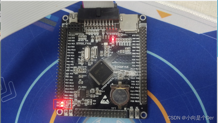
The effect of initialization
At this point, we have initialized the GPIO ports of the two LEDs. At this time, regardless of whether we ignore the ODR register and compile and burn directly, we will find that the two LED lights have been lit. This is because the ODR register defaults to The status is low level output, so it will be on.
function package
In the process of actually making products, it is rare to say that it is directly lit or turned on after initialization, and it needs to be turned on after subsequent logic control, so we need to process the above code. According to the previous idea, it should
be It is to directly operate the corresponding ODR register to realize turning on and off the light, but this is not conducive to the later maintenance of the code. Maybe after a week or two, you can’t understand your own code when you come back, so we use the macro definition to Make a package for the operation of turning on and off the lights. I have two methods here. The two lights use different methods. You can do it according to your own preferences.
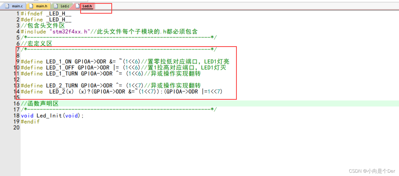
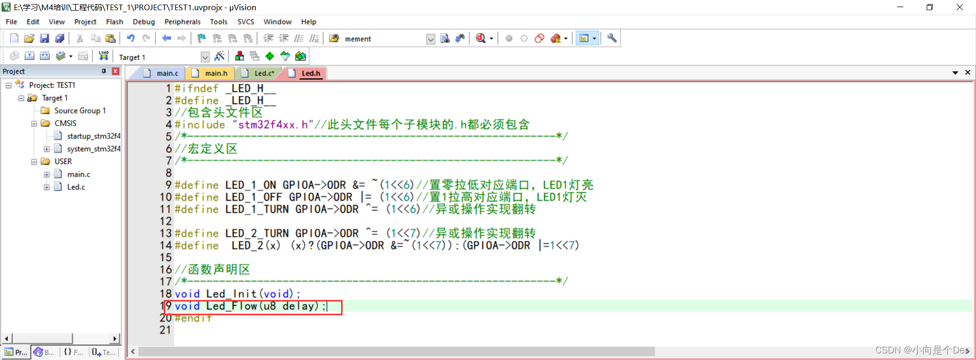
Directly separate the two macro definitions
The first way is to directly define a LEDn_ON and a LEDn_OFF respectively by macro. The specific writing method is as follows:
// An highlighted block
#define LED_1_ON GPIOA->ODR &= ~(1<<6)//置零拉低对应端口,LED1灯亮
#define LED_1_OFF GPIOA->ODR |= (1<<6)//置1拉高对应端口,LED1灯灭
//这个比较好理解,直接对对应端口的控制位写零写一。
Use conditional operators
The second way is to use the conditional operator to realize, when the macro is defined, it is defined as LED_n(x); when x is not 0, execute (GPIOA->ODR &=~(1<<7); control the corresponding GPIO When the position is 0, the IO port is pulled down, and the small light is on; when x=0, execute (GPIOA->ODR |=1<<7) to pull the corresponding bit high, and the small light is off.
#define LED_2(x) (x)?(GPIOA->ODR &=~(1<<7):(GPIOA->ODR |=1<<7))
Where should the macro definition be placed? We mentioned this in the previous article. When we wrote the header file, we also specially distinguished an area for storing macro definitions. The macro definition at this time is placed here.
Then call the above two encapsulated macros into the initialization, so that the LED is off by default.

After compiling and burning, it can be found that the LED is off by default after power-on.
Encapsulate functions to achieve simple functions
After the above operations, the on and off of the LED has been packaged, and the next step is to package the corresponding functions, such as marquees, running lights, and flashing operations. This type of operation is generally encapsulated by a functional function rather than directly coded in while(1).
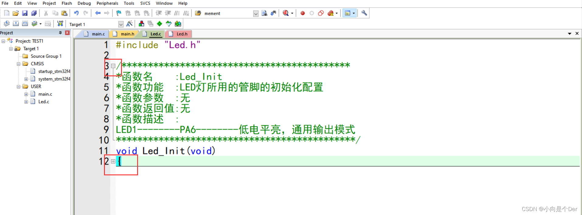
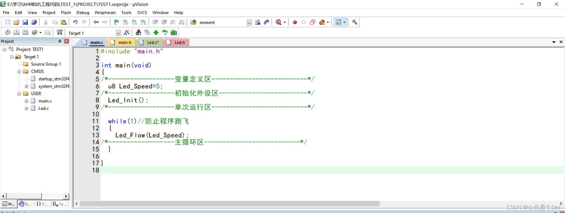
Let's implement a running water lamp here. Check a little trick. If we have a function code that is written for a long time, it is troublesome to turn it back. You can right-click anywhere in the code ------> select the position of 1, --------- -> Click once on the position of 2.
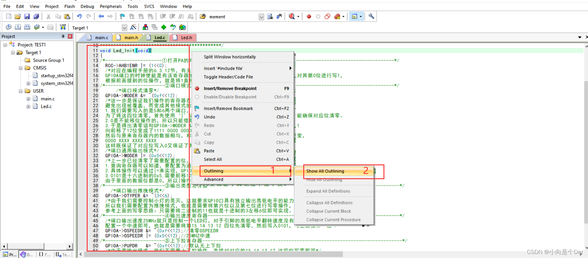
The fold symbol on the left will appear, click to fold the entire function.
//第一步,写注释
/***********************************************
*函数名    :Led_Flow
*函数功能  :实现一个简单的流水灯(非阻塞)
*函数参数  :u8 delay
*函数返回值:void
*函数描述  :灯1亮 灯1灭 灯2亮  灯2灭灯1亮(非阻塞)
delay 用来控制流水灯的速度。
*********************************************/
//第二步写函数,由于是非阻塞的流水灯,所以是不能使用while(i--)的那种死等的延时的。
void Led_Flow(u8 delay)
{


	static u8  n=1;
	static u32 cnt=0;
	if(n==1){

    LED_1_ON;}
	if(n==2){

    LED_2(1);}

	cnt++;
	//延时切换灯
	if(cnt>50000*delay)  //不精准延时
	{


		if(n==1)
		{

    LED_1_OFF; }
		if(n==2)
		{


			LED_2(0);
		}
		n++;    //往后切灯
		if(n>2)
		{


		  n=1;
		}
		cnt=0;
	}
}
Then the function declaration is called in the main function;
the main function call needs a Led_Speed to pass the parameter because a delay parameter that can adjust the speed is set.
Then compile and download, you can achieve the following effect:

KEIL MDK some tips
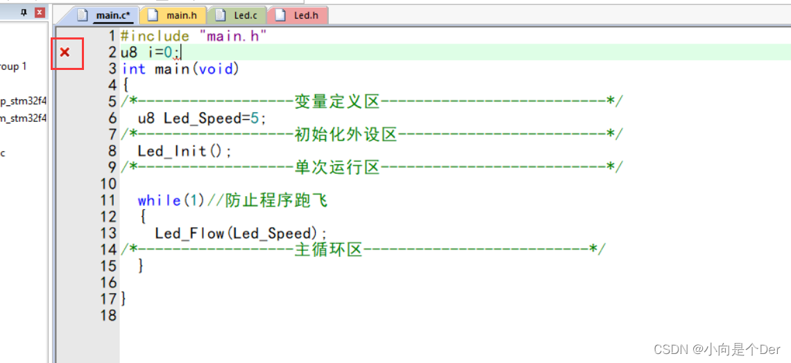
A small red cross always appears on the left side of the code
If there is a small red cross on the right side of the code, but there is no problem in compiling, as shown in the figure below, this is because KEIL has enabled Dynamic Syntax Checking by default (the reason for dynamic syntax checking) and it looks very annoying. Here we manually close it. one time.
Steps:
1. Click the wrench in the figure below
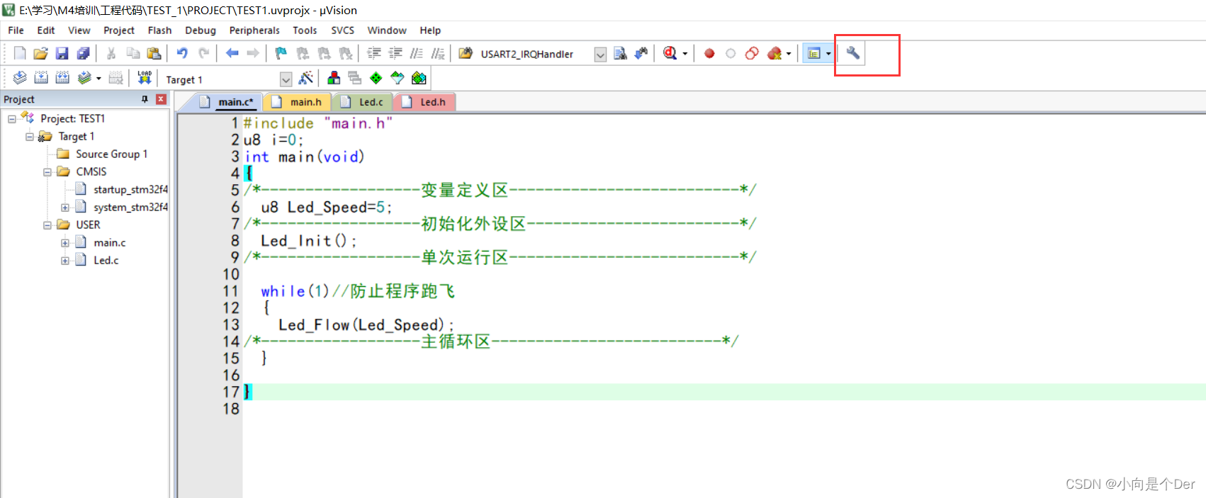
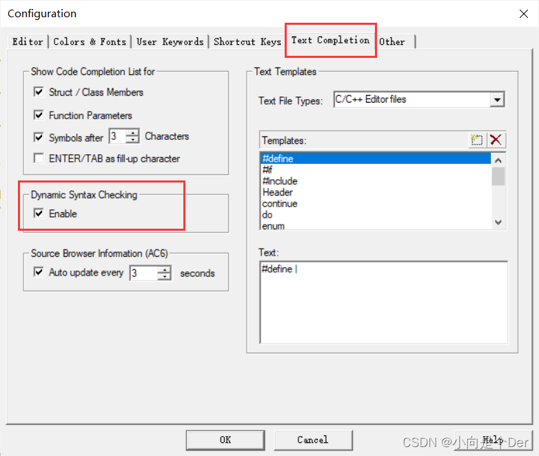
2. Select Text Completion -----------> in the pop-up box and uncheck the check box under Dynamic Syntax Checking.
2. The same project can be compiled by others, but not by yourself
This kind of problem is very likely that your own version is inconsistent with other people's versions. The new version of KEIL may not even be able to compile some official routines. When encountering this kind of problem, double-clicking the error reporting option below will jump to some official documents showing that some things are undefined.
This is caused by the too new version of the compiler.
An error similar to the following:
…/CMSIS/Include\core_cmFunc.h(614): error: unknown register name 'vfpcc' in asm
__ASM volatile ("VMSR fpscr, %0" : : "r" (fpscr) : "vfpcc" );
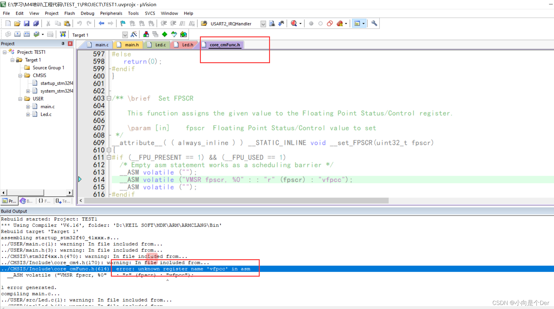
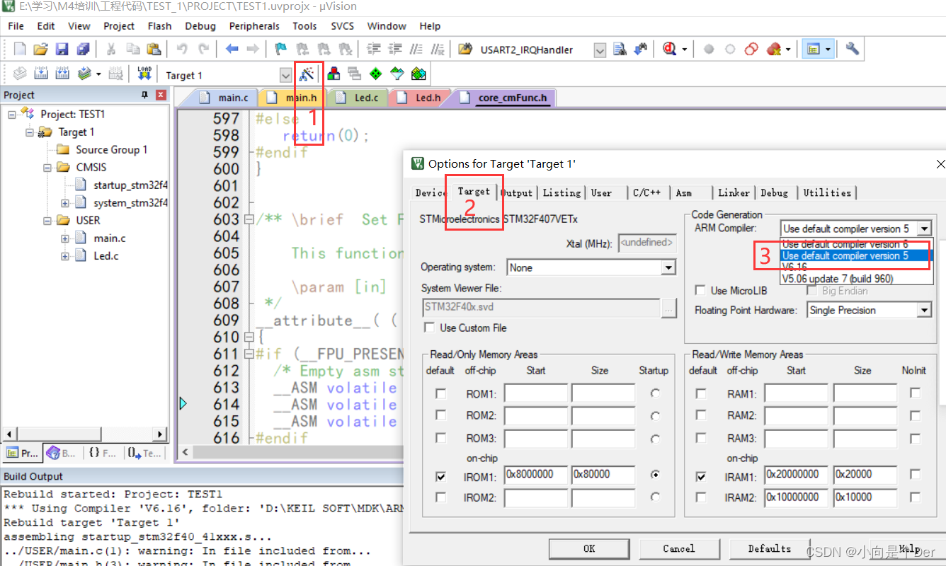
Solution: Click the magic wand at position 1, then select Target at position 2, then select the compiler version at position 3 as 5, and then recompile.
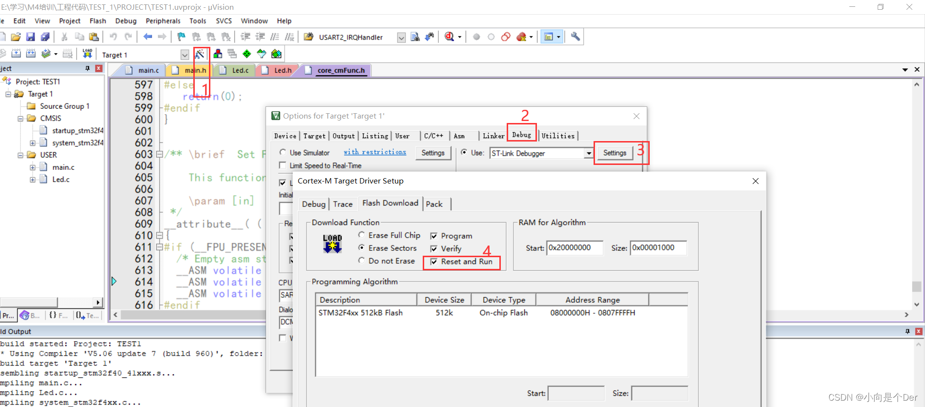
Always press reset manually after ST-LINK burning
This can also be set to allow it to automatically complete the reset operation for us. Click the magic wand, then select Debug, pay attention to select ST-LINK and then click settings, and select the check box in box 4 on the pop-up box. .
Modify font size and font
Keil MDK5 method to modify color matching, font and font size http://t.csdn.cn/MPqpH
location code error
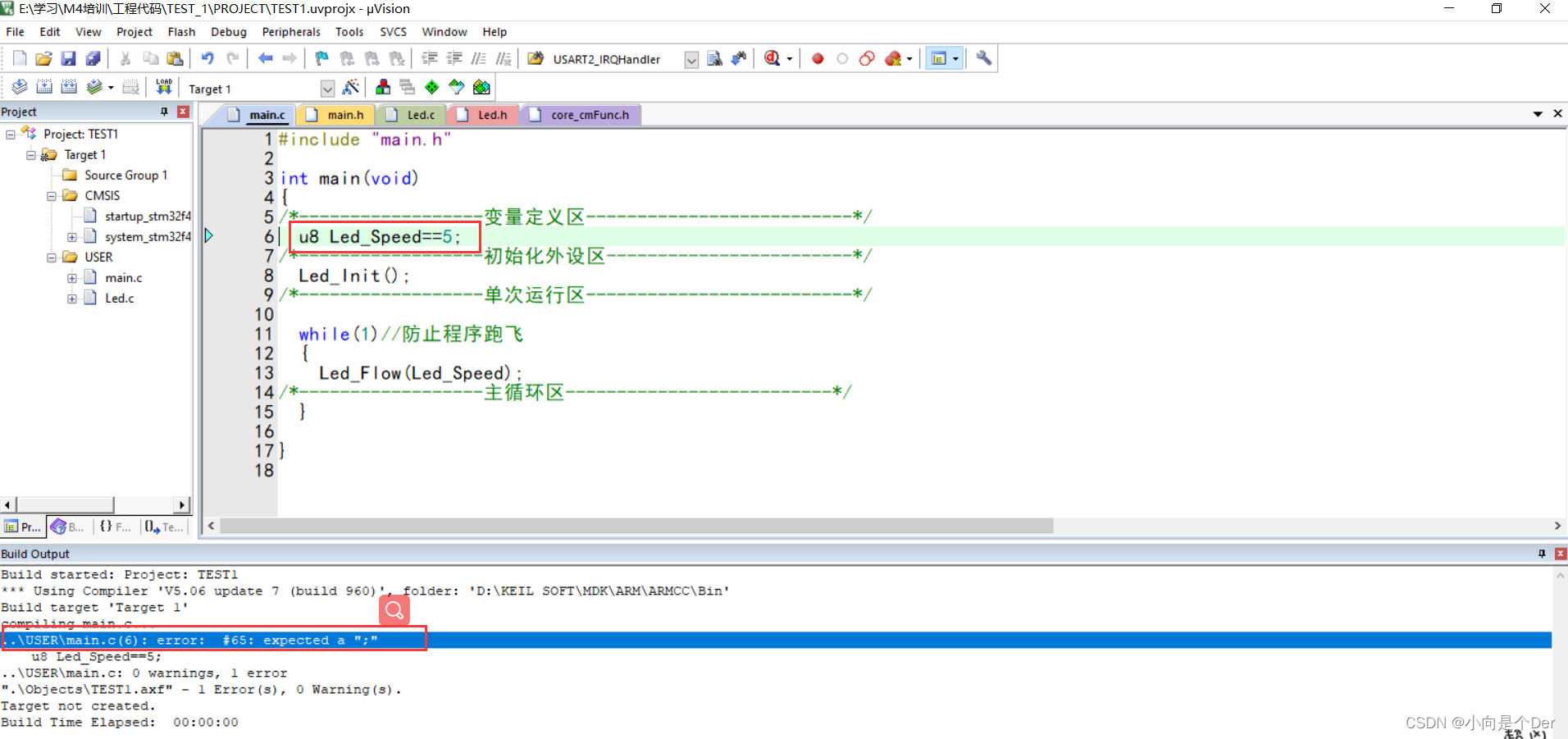
The first category, ...\USER\main.c(6): error: #65: expected a ";" The
prompt below is a small error, this kind of error directly clicks the error and it will jump to the corresponding position, at the jump position Just look for your own grammatical errors carefully. Sometimes the location and the type of error reported are not necessarily accurate, but generally you can search near the location. As shown in the figure below, the error is that there is one missing in the sixth line of main.c The semicolon is actually an extra = sign added to the assignment operator on line 6.
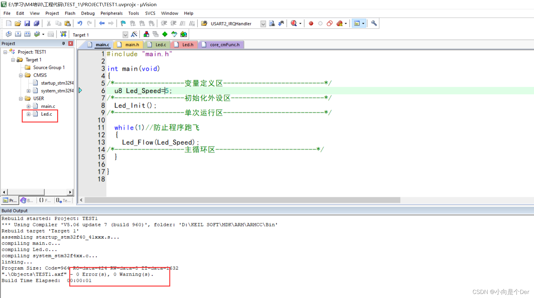
The second category, .\Objects\TEST1.axf: Error: L6218E: Undefined symbol Led_Flow (referred from main.o).
The error is Errors, and E is capitalized. This kind of error is generally undefined, or repeatedly defined, or It is an error caused by not adding the corresponding .c file to the project.
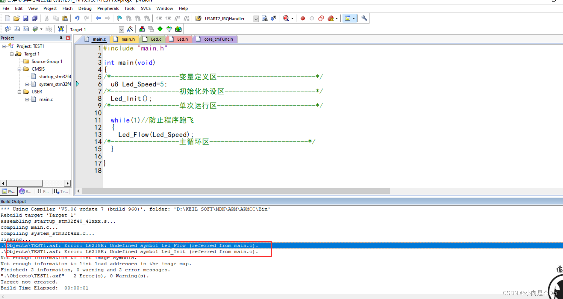
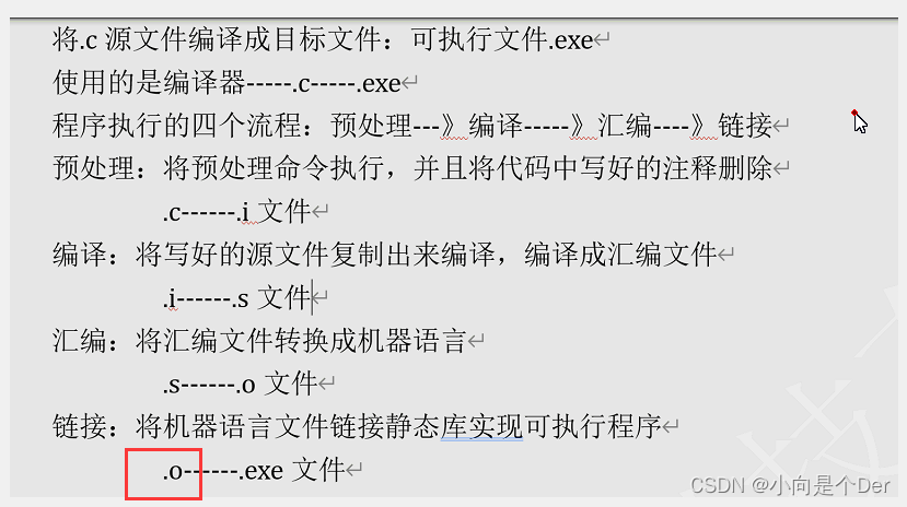
He will also point out the place and the content of the error report. The error report in the figure below means that the function Led_Flow is not found in main.o, and main.o here is actually main.c; the entire .C compilation process is shown in the figure below Note:
After re-adding Led.c into the project, the error can be resolved.