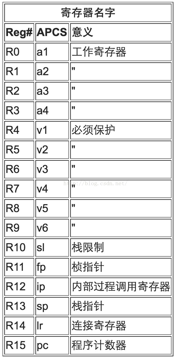
- In the program, we can use 14 of the 16 general registers to save our own data, r13 and r15 are sp and pc registers, we can not use.
- ATPCS specifies that the stack pointer should be 8-byte aligned.
- ATPCS stipulates that the called function must ensure that the contents of r4-r11 remain unchanged before and after execution, that is, the called function must save r4-r11 before starting and restore it before returning. As shown below:
routine_name
                    STMFD sp!, {r4-r12, lr} ; stack saved registers
                    ; body of routine
                    ; the fourteen registers r0-r12 and lr are available
LDMFD sp!, {r4-r12, pc} ; restore registers and return- ATPCS stipulates that during function calls, r0-r3 are used to pass parameters, and more than 4 parameters are saved in the stack. The return value must be stored in r0.
- For multi-register push and pop instructions, such as LDM and STM, the register numbers in the register list must be in ascending order.
- Double-word load and store instructions, LDRD and STRD, operand registers are two adjacent registers, Rd and Rd + 1, and the register number of this Rd must be an even number.
- Use register names rather than physical register numbers when writing assembly routines. This makes it easier to reallocate registers and to maintain the code.
- In order to save registers, we can store some variables with relatively few digits in a register, and then we can take out the corresponding variables through the shift operation. See the example below:
sample = table[index];
index += increment;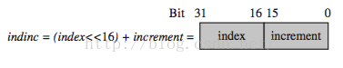
The above C code can be implemented with the following assembly code:
LDRB sample, [table, indinc, LSR#16] ; table[index]
ADD indinc, indinc, indinc, LSL#16 ; index+=increment