PLC shift cycle instruction
One, shift instruction
Shift instructions include unsigned number shift and signed number shift. The unsigned number shift includes the word left shift instruction, the word right shift instruction, the double word left shift instruction and the double word right shift instruction; the signed number shift includes the integer right shift instruction and the double integer right shift instruction.
1. Unsigned number shift instruction
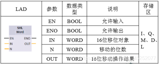
(1) Word left shift instruction When the allowed input EN bit is high level "1", the word left shift instruction will be executed, and the content specified by the IN terminal will be sent to the low word of accumulator 1 , And shift the number of bits specified by the N end to the left, and then write it into the address specified by the OUT end.
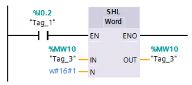
The working principle of the word shift instruction: In
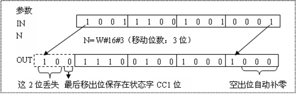
the program shown in the figure, when the state of I0.2 is "1", the data in MW2 is read into the low word of accumulator 1, and the content of the low word of accumulator 1 Shift 1 bit to the left (N=W#16#1), and then write the shifted content into MW10. Note that the content in MW2 has not changed.
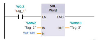
To see the effect of shifting in the same memory word, you can assign the same address to the IN and OUT terminals, that is, store the shifted result back to the shifted
address space.
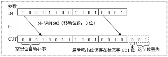
(2) Word right shift instruction
When the state of the allowed input EN is "1", the word right shift instruction will be executed.
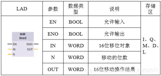
The working principle of the word shift right instruction:
(3) Double word shift left instruction The
double word shift left instruction is the shift object is 32 bits, when the EN terminal is "1", the CPU reads the contents of the IN terminal into the accumulator 1, and The content in the accumulator 1 is shifted to the left by the number of bits specified by the N end as a whole. During the shifting process, follow the principle of "0" when the high bit is missing and the low bit is filled.

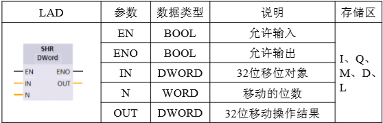
(4) Double word shift
right instruction The target of double word shift right instruction is 32 bits. When the status of EN terminal is "1", CPU will read the content specified by IN terminal into accumulator 1, and add accumulator 1. The overall right shift by the number of bits specified by the N end is carried out in accordance with the principle that the low bit is missing and the high bit is filled with "0".
2. Signed shift instruction
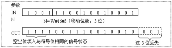
(1) Integer right shift instruction The
integer shift right instruction is different from the word and double word shift instructions. There are only right shift instructions for integers. When shifting, the low bit is lost and the high bit complements the sign bit state. That is, the high bit of positive numbers is filled with "0" and the high bit of negative numbers is filled with "1".
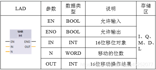
(Working principle of right shift instruction of integer)
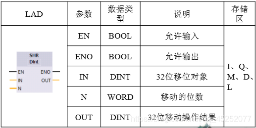
(2) Right shift instruction of double integer
The double integer shift right instruction is similar to the integer right shift instruction. The operation object of the double integer shift instruction is 32 bits.
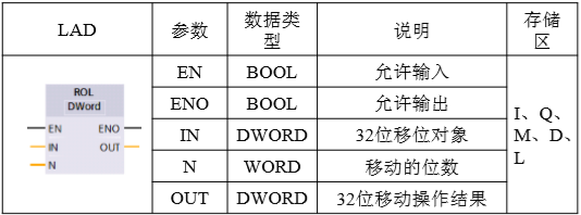
Two, cycle instructions
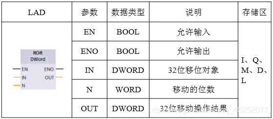
The memory area that can be operated by the cycle instruction and the names of each end are the same as those of the shift instruction. However, the shift instruction can shift the operating object in a single direction, and most of the shifted bits are lost; while the cycle instruction can cause the operating object to perform a circular shift, and the shifted bits will not be lost, but will be placed back on the vacant bits. What needs to pay attention to is the operation object of the cycle instruction, its data type is DWORD type, it is 32-bit content. The cycle instructions include double word left cycle instructions and double word right cycle instructions.
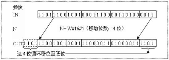
1. Double word left rotation instruction The
double word left rotation instruction has a 32-bit rotation object. When the status of the EN terminal is "1", the instruction will be executed: the CPU reads the content specified by the IN terminal into accumulator 1, and then Circulate the contents of accumulator 1 to the left by the number of bits specified by the N end, and write them into the address specified by the OUT end.
The working principle of double-word left cycle instruction:
2. Double-word right cycle instruction
The double word right rotation instruction is similar to the double word left rotation instruction, except that the operation object is rotated to the right.