The instructions described in this article comply with SIMATIC and IEC1131 instructions, not only for Siemens S7-200PLC , but also for other small PLCs as a reference. Such as the PLC of SMART200 .
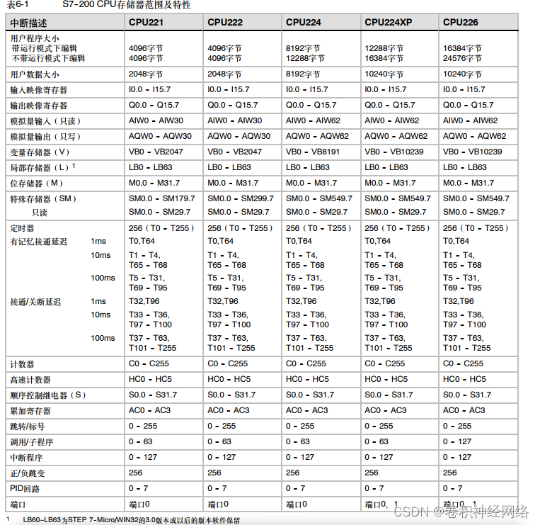
1. S7-200 memory range
As shown in the table below, it is the memory range value of each model PLC of Siemens S7-200.
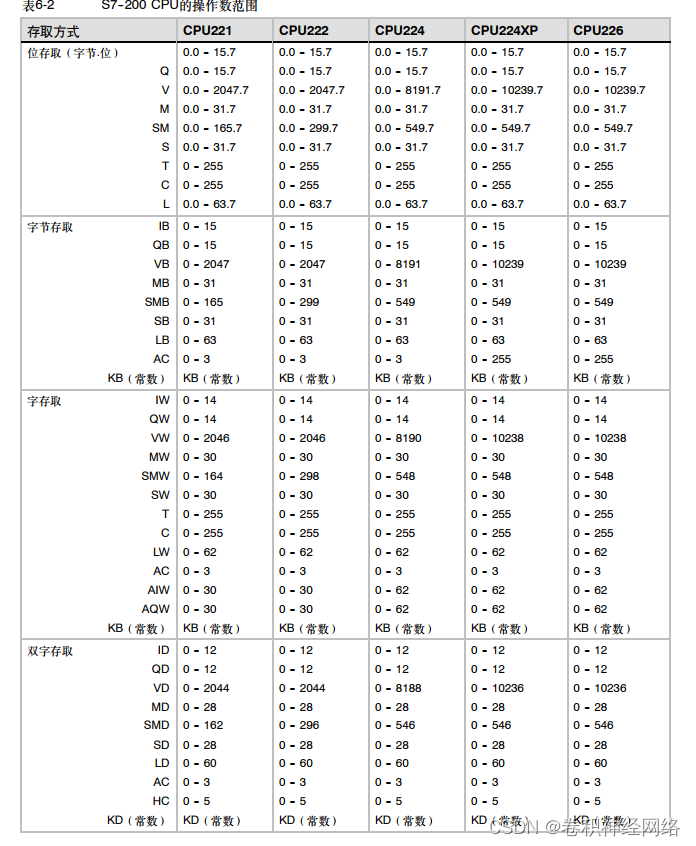
2. S7-200CPU operand range
The figure below shows the CPU operand range
3. Bit Logic Instructions
The bit logic instructions are as shown in the figure below, there are many, let's interpret them one by one .
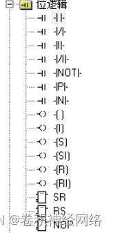
1. Contact command
As shown in the figure below: The contact instruction is divided into normally open contact, normally closed contact, immediate contact, negation instruction, edge detection and other instructions.
Normally closed contact: when the contact value is 1, it is closed or connected, and when the contact value is 0, it is disconnected;
Normally closed contact: opposite to normally open contact;
Immediate contact: directly interact with physical input and output, without going through the input and output image registers, and without scanning and refreshing.
Inversion instruction: Invert the previous calculated value, if the previous value is 1, then the latter will be 0;
Rising edge detection: The input value jumps once from 0 to 1, and the rising edge turns on a PLC scan cycle
Falling edge detection: The input value jumps from 1 to 0 once, then the falling edge turns on a PLC scan cycle
Note: red? It is the bit soft component to be input, that is, the contact value or the input value.

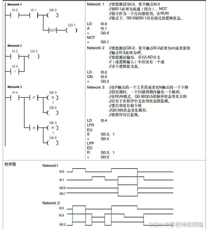
The sample program of the contact instruction is shown in the figure below
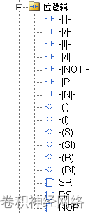
2. Coil command
Coil commands include output coil, immediate output, set command, reset command, immediate set command, immediate reset command, empty command, etc.
Output command: that is, it is 1 when it is connected before, and it is 0 when it is disconnected before;
Immediate output: immediately output to the physical IO point without scanning cycle;
Set command: keep the N soft components starting from the specified address in 1 state;
Reset command: keep the N soft components starting from the specified address in the state of 0
Empty instruction: do nothing

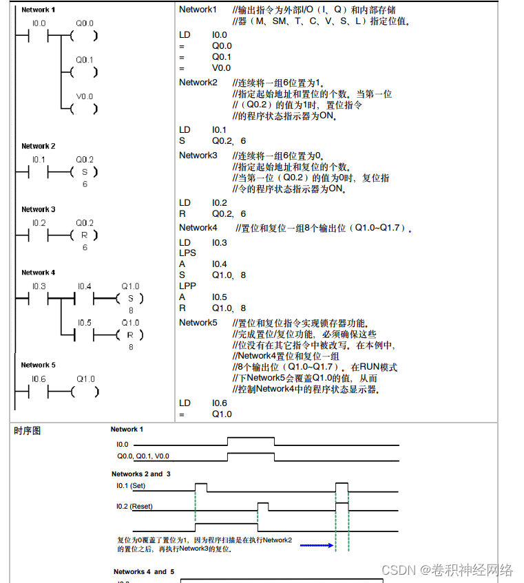
The sample program of the coil instruction is as shown in the figure below
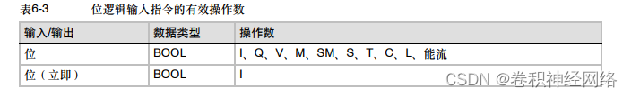
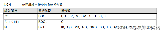
3. Valid soft elements (or operands) of bit logic instructions
The effective device (or operand) of the bit logic instruction is the symbol that can be input at the red? of the value bit logic instruction, and its valid range is as follows: