The function and basic structure of the CPU: The central processing unit (CPU) is composed of arithmetic unit and controller. Among them, the function of the controller is responsible for coordinating and controlling the sequence of instructions of the various components of the computer to execute the program, including fetching instructions, analyzing instructions, and executing instructions; the function of the arithmetic unit is to process data. The specific functions of the CPU include:
(1) Instruction control: complete the operations of fetching instructions, analyzing instructions and executing instructions, that is, sequence control of the program
(2) Operation control: the function of an instruction is often realized by a combination of several operating signals . The CPU manages and produces the operation signal of each instruction fetched from the memory, and sends various operation signals to the corresponding components, thereby controlling these components to act according to the requirements of the instruction.
(3) Time control: Time control of various operations. Time control should provide the necessary control signals for each instruction in chronological order.
(4) Data processing: perform arithmetic and logical operations on data
(5) Interrupt processing: deal with abnormal situations and special requests that occur during computer operation.
In a computer system, the central processing unit is mainly composed of arithmetic units and controllers. Two major components, as shown below
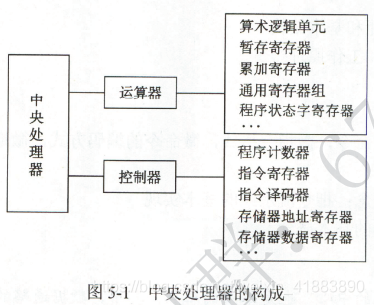
1. The arithmetic unit The
arithmetic unit receives the commands sent from the controller and executes the corresponding actions to process and process the data. The arithmetic unit is the center of the computer processing data. It is mainly composed of arithmetic logic unit (ALU), temporary storage register, accumulating register (ACC), general register group, program status word register (PSW), shifter, counter (CT), etc.
(1) Arithmetic logic unit: The main function is to perform arithmetic/logical operations.
(2) Temporary storage register: Use temporary storage to read data from the main storage. This data cannot be stored in a general-purpose register, otherwise its original content will be destroyed. The temporary storage register is transparent to the application programmer.
(3) Accumulation register: It is a general-purpose register used to temporarily store the result information of ALU operations, and can be used as an input terminal for addition operations.
(4) General register group: such as AX, BX, CX, DX, SP, etc., used to store operands (including source operands, destination operands and intermediate results) and various address information. SP is the stack pointer, used to indicate the address of the top of the stack.
(5) Program status word register: retains various status information established by the results of arithmetic logic operation instructions or test instructions, such as overflow flag (OP), symbol flag (SF), zero flag (ZF), carry flag (CF) ). These bits in the PSW participate in and determine the completion of the micro-operation
(6) Shifter: shift the operand or the result of the operation
(7) Counter: control the number of steps in the multiplication and division operation
2, the controller
controller is the entire system The command center, under the control of the controller, makes the arithmetic unit, memory and input/output equipment and other functional components form an organic whole, and directs the whole machine to coordinate work according to the requirements of the instructions. The basic function of the controller is to execute instructions, and the execution of each instruction is realized by a set of micro-operations issued by the controller.
There are two types of controllers: hard-wired controllers and microcontrollers.
The controller is composed of a program counter (PC), instruction register (IR), instruction decoder, memory address register (MAR), memory data register (MDR), timing system and micro-operation signal generator.
2.1 Program counter: used to point out the storage address of the next instruction in the main memory. The CPU fetches instructions from the main memory according to the content of the PC. Because the instructions in the program are executed sequentially, the PC has an auto-increment function.
2.2 Instruction register: used to save the instruction currently being executed
2.3 Instruction decoder: only decode the opcode field and provide specific operation signals to the controller
2.4 Storage address register: used to store the main memory to be accessed The address of the unit
2.5 stores the data register: used to store the information written to the main memory or the information read from the main memory
2.6 timing system: used to generate various timing signals, they are all obtained by the same clock (CLOCK) frequency division
2.7 Micro-operation signal generator: According to the content of IR (instruction), content of PSW (status information) and timing signals, it generates various control signals needed to control the entire computer system. Its structure has two types: combinational logic and storage logic. .
The working principle of the controller is based on the instruction operation code, the execution steps of the instruction and the condition signal to form the control signals used by the current computer components. The whole computer and hardware Xiyong operate in coordination under the control of these control signals. The
internal registers of the CPU that produce the expected execution results can be roughly divided into two categories: one is the registers visible to the user, which can be programmed, such as the Rongyong register group and the program status word register; the other is the register invisible to the user , It is transparent to users, and it is not possible to program such registers, such as memory address registers, memory data registers, and instruction registers.