Hello everyone, the next will introduce OpenGL ES 3. coordinate system and coordinate transformation.
First, the coordinate system, the coordinate space:
OpenGL is used in a Cartesian right-handed coordinate system.
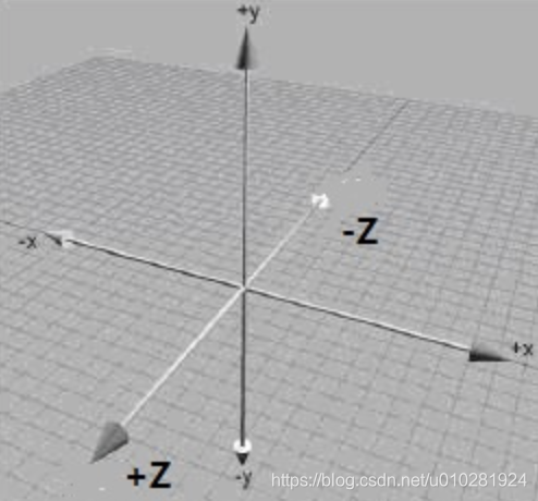
There are five important OpenGL coordinate space:
a: local space (Local Space, referred to as an object or a space (Object Space)).
b: world space (World Space).
c: observation space (View Space, otherwise known as visuospatial (Eye Space)).
d: clip space (Clip Space).
e: screen space (Screen Space).
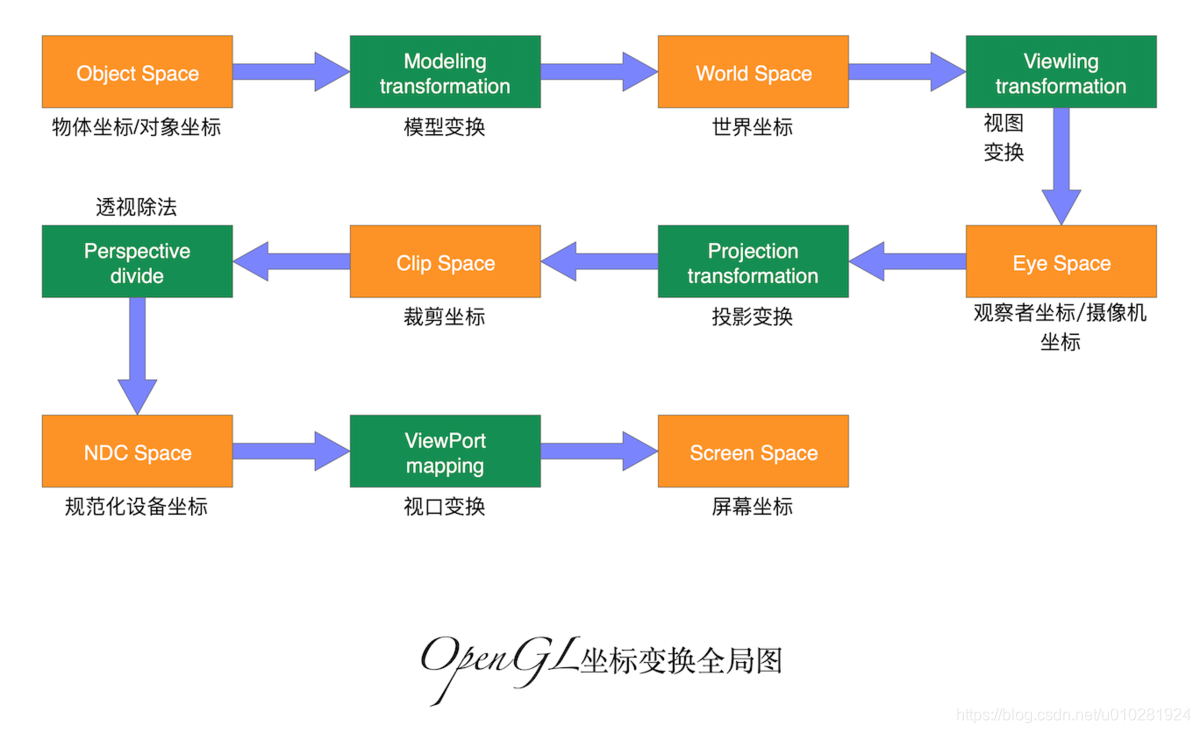
In order to coordinate transformation from one coordinate system to another coordinate system, we need to use several transformation matrix, the most important ones are the model (the Model), observed (View), the projection (Projection) three matrix.
Vertex coordinates of the object and then the initial partial space (Local Space), here called local coordinates (Local Coordinate), after it becomes a world coordinate (world Coordinate), measured coordinate (View Coordinate), clipping coordinates (Clip Coordinate ), and finally end in the form of screen coordinates (screen Corrdinate) of. The picture below illustrates the various processes and transform what to do:

Second, the matrix operation example:
public class MatrixState {
    private static float[] mProjMatrix = new float[16]; //投影矩阵
    private static float[] mVMatrix = new float[16]; //视图矩阵
    private static float[] currMatrix; //模型矩阵

    private static float[] mMVPMatrix;
    public static void setCamera(
        float cx, float cy, float cz,
        float tx, float ty, float tz,
        float upx, float upy, float upz
    ){
        Matrix.setLookAtM(mVMatrix, 0, cx, cy, cz, tx, ty, tz, upx, upy, upz);
    }

    public static void setProjectOrtho(
        float left, float right,
        float bottom, float top,
        float near, float far
    ){
        Matrix.orthoM(mProjMatrix, 0, left, right, bottom, top, near, far);
    }

    public static void setProjectFrustum(
        float left, float right,
        float bottom, float top,
        float near, float far
    ){
        Matrix.frustumM(mProjMatrix, 0, left, right, bottom, top, near, far);
    }

    public static void translate(float x, float y, float z)
    {
        Matrix.translateM(currMatrix, 0, x, y, z);
    }

    public static float[] getFinalMatrix() { //计算产生总变换矩阵的方法
        //摄像机矩阵乘以变换矩阵
        Matrix.multiplyMM(mMVPMatrix, 0, mVMatrix, 0, currMatrix, 0);
        //投影矩阵乘以上一步的结果矩阵
        Matrix.multiplyMM(mMVPMatrix, 0, mProjMatrix, 0, mMVPMatrix,
                          0);
        return mMVPMatrix;
    }


}
Third, the coordinate transformation process is as follows:
Corresponding model transformation matrix is: currMatrix.
View transform matrix is corresponding: mVMatrix.
Projective transformation matrix is corresponding: mProjMatrix.
Four, shader using the example:
#version 330

layout(location = 0) in vec3 position;
layout(location = 1) in vec3 color;
layout(location = 2) in vec2 textCoord;

out vec3 VertColor;
out vec2 TextCoord;

uniform mat4 mvpMatrix;

void main()
{
    gl_Position = mvpMatrix * vec4(position, 1.0);
    VertColor = color;
    TextCoord = textCoord;
}
glUniformMatrix4fv(glGetUniformLocation(shader.programId, "mvpMatrix"),
1, GL_FALSE, MatrixState.getFinalMatrix()); // 传递总的变换矩阵
Finally, we welcome the exchange of learning together: micro letter: liaosy666; QQ: 2209115372 .
