为了满足部分IOT应用对显示的需求,高通DragonBoard 410c IOT平台提供了一个具有四路MIPI-DSI接口的高速扩展口用于提供显示支持,在DragonBoard 410c开发板设计中,通过一个DSI选择器与DSI-HDMI桥进行连接,该选择器搭载在410c上,如图1所示。

图1 MIPI DSI 0口连接示意图
在实际的工作过程中410c只能驱动HDMI和MIPI-DSI接口中的一个用于显示,在具体的实现中,该控制信号是通过一个DSI_SW_SEL_APQ信号来进行控制的,如果该信号设置为0的时候,系统将使能410c的MIPI-DSI接口,同时将DSI选择器接入到DSI-HDMI桥上,进行HDMI转换输出,否则,MIPI-DSI接口将被连接到高速扩展口上,在410c引硬件设计中为了方便用户选择通过一个拨码开关来对该功能进行控制,如图2所示,只要将S6中的开关对应的标有HDMI SET字样的信息的位拨到“ON”端就能够实现对软件控制的覆盖,强迫410c的DSI选择器选择DSI-HDMI上,实现HDMI输出,而拨到OFF端,起可以解除强制覆盖,可以接受软件控制实现DSI选择器连接选择,这种设计方式给开发者非常灵活的选择来定制自己的显示功能需求。

图2 硬件选择HDIM显示输出设置示意图
以上就是410c开发板MIPI-DSI显示的基本原理,在实际的开发和创作过程中,通常最为关键的是如何进行显示驱动的移只,让自己设计的产品能够正常稳定的显示。接着本文将向大家介绍在410c开发板上进行MIPI-DSI显示驱动的移植工作通用方法及流程,包括如何下载驱动、利用DTSI和面板文件确定XML参数以及移植驱动程序的整个流程。
一、相关准备工作
本文在移植的过程中使用的参考显示面板驱动补丁及相关信息库可以通过以下链接进行下载:
添加链接描述https://www.codeaurora.org/cgit/external/thundersoft/ihvjointlab/gcdb-kernel/tree/display/——内核空间支持
同时还可以在下面的链接下载相关的内核驱动代码patch和资料文件:
添加链接描述https://www.codeaurora.org/cgit/external/thundersoft/ihvjointlab/gcdb-user-space/tree/display/——用户空间支持
完成下载后执行以下命令通过打patch方式将驱动信息加入到对应的驱动代码中:
cd $ANDROID_BUILD_TOP/kernel
patch -p1 < 0001-ARM-dts-msm-support-truly-hx8379_a-devicetree.patch
cd $ANDROID_BUILD_TOP/ bootable/bootloader/lk
patch -p1 < 0001-bootloader-lk-add-lcd-truly-hx8379_a.patch
上面的这两种方式是参考的方式,具体执行可能应为代码环境问题,可能会出现patch冲突,这时候用户可以手动patch或者强制patch然后手动解决相关的冲突。
完成上述工作后还需要获取参考面板一些关键信息如下:
a)显示规格参数
b)GPIO引脚信号持续时间信息如RESET/LOVDD等;
c)DSI的指令序列和持续的时间信息;
d)目标帧相关信息;
二、制作内核LK和DTSI文件
1)添加面板的内核LK
a)复制参考面板驱动DTSI文件到kernel/arch/arm64/boot/dts/qcom目录下;
b)复制面板驱动头文件到bootable/bootloader/lk/dev/gcdb/display/include/目录下;
c)在android内核中添加面板;
d)禁用LK display和continuous splash display
首先通过在bootable/bootloader/lk/target/msm8916/rules.mk文件中设置DISPLAY_SPLASH_SCREEN为0,禁用continuous splash display,然后继续添加LK,参考如下方式在bootable/bootloader/lk/target/msm8916/init.c中修改和更新target_cont_splash_screen函数:
	static uint8_t splash_override;
	/* Returns 1 if target supports continuous splash screen. */
	int target_cont_splash_screen()
	{
		uint8_t splash_screen = 0;
		if(!splash_override) {
			switch(board_hardware_id())
			{
			case HW_PLATFORM_MTP:
			case HW_PLATFORM_QRD:
			dprintf(SPEW, "Target_cont_splash=1\n");
			splash_screen = 1; // Change to “0” to disable continous splash screen
			break;
			default:
			dprintf(SPEW, "Target_cont_splash=0\n");
			splash_screen = 0;
			}
		}
		return splash_screen;
	}
	最后通过在msm8xxx-cdp.dts文件中设置禁用continuous splash screen,具体如下:
	&dsi_<vendor>_720p_video{
	// qcom,cont-splash-enabled; // Disable continous splash screen
	}003B
	};
2)在xml文件中输入LCD显示面板的参数
在LCD面板厂商的xml文件中更新相关的参数,具体需要更新的相关参数如下(红色标注的部分):
<!-- Panel configuration -->
<PanelType>0</PanelType> // 0 stands for video mode panel, 1 stands for command mode panel
<PanelFrameRate>60</PanelFrameRate>
<!-- Panel Resolution -->
<PanelWidth>720</PanelWidth>
<PanelHeight>1280</PanelHeight>
<HFrontPorch>140</HFrontPorch>
<HBackPorch>164</HBackPorch>
<HPulseWidth>8</HPulseWidth>
<HSyncSkew>0</HSyncSkew>
<VBackPorch>4</VBackPorch>
<VFrontPorch>8</VFrontPorch>
<VPulseWidth>4</VPulseWidth>
<!-- Panel Color Information -->
<ColorFormat>24</ColorFormat> // 24bpp
<!-- Panel Command information -->
<OnCommand>"0x29, 0x01, 0x00, 0x00, 0x00, 0x00, 0x02, 0xFF, 0xEE,0x29, 0x01, 0x00, 0x00, 0x00, 0x00, 0x02, 0xFB, 0x01,.......
0x29, 0x01, 0x00, 0x00, 0x78, 0x00, 0x02, 0x29, 0x00"
</OnCommand> // add your panel on commands from LCD vendor
<OffCommand>"0x05, 0x01, 0x00, 0x00, 0x32, 0x00, 0x02, 0x28, 0x00,
… … …
0x05, 0x01, 0x00, 0x00, 0x78, 0x00, 0x02, 0x10, 0x00"
</OffCommand> // add your panel off commands from LCD vendor
<OnCommandState>0</OnCommandState> // 0 stands for lp mode
<OffCommandState>1</OffCommandState> // 1 stands for hs mode

<!-- Video mode panel information -->
<HSyncPulse>1</HSyncPulse>
<BLLPEOFPowerMode>1</BLLPEOFPowerMode>
<BLLPPowerMode>1</BLLPPowerMode>
<TrafficMode>2</TrafficMode>
<!-- Panel Reset Sequence -->
<ResetSequence>
<PinState1>1</PinState1>
<PulseWidth1>20</PulseWidth1>
<PinState2>0</PinState2>
<PulseWidth2>2</PulseWidth2>
<PinState3>1</PinState3>
<PulseWidth3>20</PulseWidth3>
</ResetSequence>
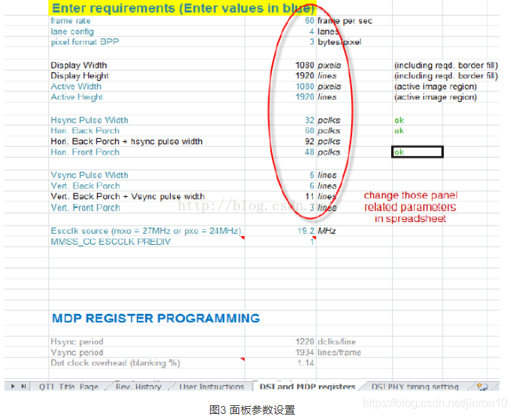
3)计算DSI PHY定时寄存器
在这里可以利用高通提供的D-PHY自动计算表来完成计算,具体的计算表格到DragonBoard 410c高通官网资料库中下载dsi相关资料包DSI_Timing_Parameters.xls文件中,打开该文件,在DSI and MDP registers工作表中输入面板分辨率、FPS、色彩深度等参数信息,如下图3所示。
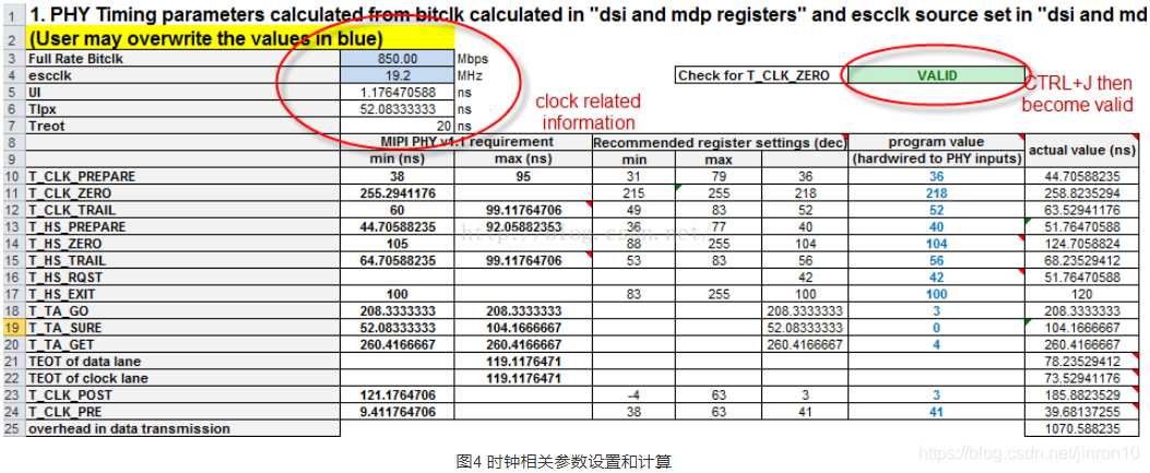
通过DSI PHY可以设置和计算相关的时钟速率,如下图4所示。
最后可以计算得到DSI PHY registers的值,如下图5所示。
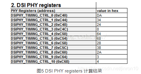
完成计算后,将这些参数值输入到.xml文件中,如下:
<!-- Panel Timing -->
<PanelTimings>"0xDA, 0x34, 0x24, 0x00, 0x64, 0x68,
						0x28, 0x38, 0x2A, 0x03, 0x04, 0x00"</PanelTimings>
<TClkPost>0x03</TClkPost>
<TClkPre>0x41</TClkPre>
三、输入背光控制参数
在驱动中有三个参数可以用于控制LCD背光,具体如下:
	“bl_ctrl_pwm” = Backlight controlled by PWM GPIO
	“bl_ctrl_wled” = Backlight controlled by WLED
	“bl_ctrl_dcs” = Backlight control by DCS commands
其中采用WLED方式来控制背光源,那么在xml文件中输入一下参数:
<!-- Backlight -->
	<BLInterfaceType>1</BLInterfaceType>
	<BLMinLevel>1</BLMinLevel>
	<BLMaxLevel>4095</BLMaxLevel>
	<BLStep>100</BLStep>
	<BLPMICModel>"PMIC_8xxx"</BLPMICModel>
	<BLPMICControlType>1</BLPMICControlType> // 1 stands for Backlight controlled by WLED.
其他两种方式与具体的硬件配置和电路相关,为了简化移植过程在本文不做讨论。
四、设置DSI显示面板相关的GPIO引脚
首先在device/qcom/common/display/tools/platform-8xxx.xml文件中输入相关的GPIO参数,如下:
<PlatformId>"msm8xxx"</PlatformId>
	<!-- GPIO configuration -->
	<ResetGPIO>
		<PinSource>"msmgpio"</PinSource>
		<PinId>25</PinId>
		<PinStrength>3</PinStrength>
		<PinDirection>1</PinDirection>
		<PinPull>0</PinPull>
		<PinState>1</PinState>
	</ResetGPIO>
<EnableGPIO>
	<PinSource>"msmgpio"</PinSource>
	<PinId>32</PinId>
	<PinStrength>3</PinStrength>
	<PinDirection>1</PinDirection>
	<PinPull>0</PinPull>
<PinState>1</PinState>
....
</EnableGPIO>
五、在DTS文件中添加面板设备树
在arch/arm/boot/dts/qcom/下修改msm8xxx-qrd.dts文件增加显示面板驱动树,具体可以参考以下例子:
/include/ "dsi-panel-<vendor>-720p-video.dtsi"
&mdss_mdp {
	qcom,mdss-pref-prim-intf = "dsi";
};
&mdss_pinmux {
	qcom,num-grp-pins = <3>;
	qcom,pins = <&gp 32>, <&gp 25>, <&gp97>;
};
&mdss_dsi0 {
	qcom,dsi-pref-prim-pan = <&dsi_<vendor>_720p_video>;
	pinctrl-names = "default", "sleep";
	pinctrl-0 = <&mdss_dsi_active>;
	pinctrl-1 = <&mdss_dsi_suspend>;
六、增加显示面板驱动头文件和在LK中检测显示面板ID
在bootable/bootloader/lk/target/msm8xxx/oem_panel.c中增加显示面板头文件,如下:
#include "include/panel_toshiba_720p_video.h"
#include "include/panel_nt35590_720p_video.h"
#include "include/panel_nt35590_720p_cmd.h"
#include "include/panel_hx8394a_720p_video.h"
+#include "include/panel_nt35521_720p_video.h"
在enum中增加<vendor>_<resolution>_VIDEO_PANEL 参数,如下:
enum {
	TOSHIBA_720P_VIDEO_PANEL,
	NT35590_720P_CMD_PANEL,
	NT35590_720P_VIDEO_PANEL,
	HX8394A_720P_VIDEO_PANEL,
	+NT35521_720P_VIDEO_PANEL,
	UNKNOWN_PANEL
};
在panel_list_supp_panels结构体中增加<vendor>_<resolution>_VIDEO_PANEL参数:
static struct panel_list supp_panels[] = {
	{"toshiba_720p_video", TOSHIBA_720P_VIDEO_PANEL},
	{"nt35590_720p_cmd", NT35590_720P_CMD_PANEL},
	{"nt35590_720p_video", NT35590_720P_VIDEO_PANEL},
	{"hx8394a_720p_video", HX8394A_720P_VIDEO_PANEL},
	+{"nt35521_720p_video", NT35521_720P_VIDEO_PANEL},
};
在init_panel_data函数中增加<vendor>_<resolution>_VIDEO_PANEL参数:
static void init_panel_data(struct panel_struct *panelstruct,
struct msm_panel_info *pinfo,
struct mdss_dsi_phy_ctrl *phy_db)
{
 switch (panel_id) {
+case NT35521_720P_VIDEO_PANEL:
	+ panelstruct->paneldata = &nt35521_720p_video_panel_data;
	+ panelstruct->panelres = &nt35521_720p_video_panel_res;
	+ panelstruct->color = &nt35521_720p_video_color;
	+ panelstruct->videopanel = &nt35521_720p_video_video_panel;
	+ panelstruct->commandpanel = &nt35521_720p_video_command_panel;
	+ panelstruct->state = &nt35521_720p_video_state;
	+ panelstruct->laneconfig = &nt35521_720p_video_lane_config;
	+ panelstruct->paneltiminginfo
	= &nt35521_720p_video_timing_info;
	+ panelstruct->panelresetseq
	= &nt35521_720p_video_panel_reset_seq;
	+ panelstruct->backlightinfo = &nt35521_720p_video_backlight;
	+ pinfo->mipi.panel_cmds
	= nt35521_720p_video_on_command;
	+ pinfo->mipi.num_of_panel_cmds
	= NT35521_720P_VIDEO_ON_COMMAND;
	+ memcpy(phy_db->timing,
	nt35521_720p_video_timings, TIMING_SIZE);
break;
在oem_panel_select函数中选择面板ID:
enum target_subtype {
	HW_PLATFORM_SUBTYPE_SKUAA = 0,
	HW_PLATFORM_SUBTYPE_SKUF = 1,
	HW_PLATFORM_SUBTYPE_SKUAB = 2,
	HW_PLATFORM_SUBTYPE_SKUG = 3,
	+HW_PLATFORM_SUBTYPE_720P = 5,
};
switch (hw_id) {
	case HW_PLATFORM_MTP:
	case HW_PLATFORM_QRD:
	if (hw_subtype == HW_PLATFORM_SUBTYPE_720P)
	+ panel_id = NT35521_720P_VIDEO_PANEL;
	else
	panel_id = nt35590_panel_id;
	break;
	default:
	dprintf(CRITICAL, "Display not enabled for %d HW type\n", hw_id);
	return false;
七、编译下载images,并通过adb调试
a) 刷新410c设备emmc_appsboot.mbn和boot.img文件,具体刷新方法可以参考链接:
b) 重启410c,确认面板是否点亮,如果没有,依次检查初始化命令、复位序列,同事测量DSI时钟通道和数据通道的序号进行调试。
c)如果没有DSI时钟输出,那么通过如下adb命令查看其相关的时钟信号,进一步确定问题所在。
》adb root
》adb remount
》 adb shell
》#mount –t debugfs none /sys/kernel/debug
》 #cd /sys/kernel/debug/clk/dsi1_byte_clk
》 #cat measure
