本文主要分析TC1.6内核架构下的中断管理方式,包括两种:硬件管理方式和软件管理方式。
本文首先简要介绍TC1.6内核的中断系统,以此为基础便于后面的理解;然后通过对两种中断管理方式对应的代码的分析,分别说明硬件管理和软件管理方式的原理;最后总结两者的特点及二者之间区别。
一、TC1.6系列内核中断系统简介
TC297、TC275、TC397等MCU均以TC1.6(或TC1.6.1)为内核,以下是TC1.6内核的中断系统概述:

其中主要介绍了如下几点:
1.中断服务请求对应的服务提供者可以是CPU,也可以是DMA;
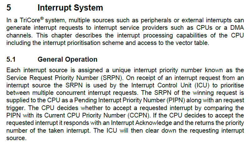
2.中断控制单元(ICU)负责中断优先级的仲裁,胜出者作为挂起中断优先级号(PIPN)提供给CPU;
3.CPU将PIPN与当前正在执行的任务的优先级号(CCPN)进行比较,决定是否切换任务/中断,若PIPN大于CCPN则执行{ CCPN = PIPN }。
以上是从中断服务请求发出到CPU接受请求的过程,我们再来看CPU处理中断服务请求的过程,主要是CPU如何查找并跳转到对应的中断服务函数(或中断向量)的过程,如下所示:

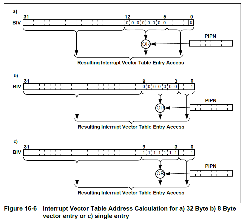
通过以上介绍可知CPU计算中断向量地址主要根据寄存器BIV(The Base of Interrupt Vector Table register)和发生中断的优先级(PIPN),具体计算方式有三种(实际上是两种,通过设置BIV的最低位VSS来选择)。
------------------------------------------------------------------------------------------------------------------------------------------------------------------------------------
二、中断的两种管理方式
按照官方的说法,中断的管理方式有两种:硬件管理和软件管理。以下是官方对两种方式的介绍:
 1 /*Documentation */
 2 /** \addtogroup IfxLld_Cpu_Irq_Usage
 3  * \{
 4  *
 5  * This page describes how to use interrupts with application framework.\n
 6  *
 7  * \section IfxLld_Cpu_Irq_Terminology Interrupts Terminology:
 8  * \subsection IfxLld_Cpu_Irq_HWManaged Hardware Managed Interrupt Mechanism.
 9  *
10  * Hardware managed interrupts have static interrupt vector which are defined for each priority separately.每个优先级对应一个中断向量
11  * These vectors have jump instruction to the interrupt handler.
12  *
13  * Advantages:\n
14  * This mechanism has less interrupt latency time.
15  *
16  * \subsection IfxLld_Cpu_Irq_SWManaged Software Managed Interrupt Mechanism.
17  * Software managed interrupts have single interrupt vector statically defined at vector position 255.
18  * This address is assigned to BIV during startup.\n 启动时将该单个中断向量的地址加载到BIV寄存器中
19  * For Tricore, this vector position is important, because whenever an interrupt occurs, with whichever priority,
20  * the execution control jumps to this vector position. The code at this vector position will:\n
21  * 1) fetch the priority of the targetted interrupt.\n
22  * 2) fetch the interrupt handler defined for this priority (this is done by Interrupt handler installation. Refer
23  * \ref IfxLld_Cpu_Irq_Step4\n
24  * 3) Then call the handler as notmal function call.
25  * 发生中断时,跳转到该中断向量地址,获取中断的优先级进而获取中断服务函数并执行
26  * Advantages:\n
27  * This kind of mechanism is useful when project wants to change the handler for an interrupt during runtime.
28  *
29  * Disadvantages:\n
30  * This mechanism has more interrupt latency time.
31  *
32  * of the interrupt and in tand jumps to the function
33  *
1.首先看硬件管理方式,其特点是:每个优先级都各自对应一个中断向量用于向中断服务函数的跳转,从而组成一个容量为256的中断向量表。这种方式的中断管理代码在HighTec安装目录下的cint_tc29x.c中定义,具体代码如下。(注:为了简洁,删除了关于Trap的内容和部分中断向量的定义)
/*==================================================================== * Project: Board Support Package (BSP) * Function: C interface for TriCore trap and interrupt handlers * * Copyright HighTec EDV-Systeme GmbH 1982-2018 *====================================================================*/ #include <machine/intrinsics.h> #include <machine/wdtcon.h> #include "cint.h" #include "tc_inc_path.h" #include TC_INCLUDE(TCPATH/IfxCpu_reg.h) #include TC_INCLUDE(TCPATH/IfxCpu_bf.h) /* This variable is set to 1 after the vectabs are initialized. */ static int _init_vectab_initialized[3] = {0, 0, 0}; /* This structure describes interrupt handlers and their arguments. */ typedef struct _Hnd_arg { void (*hnd_handler)(int); int hnd_arg; } Hnd_arg;
/* This array holds the functions to be called when an interrupt occurs. */ Hnd_arg Cdisptab[MAX_INTRS]; void __int_handler(int arg);
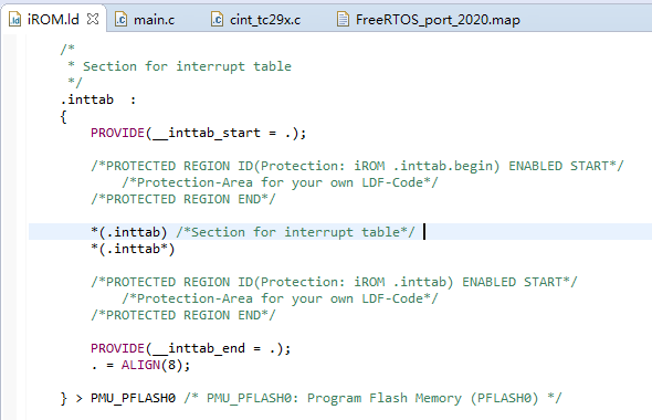
/* This is the default interrupt vector table, which consists of 32 entries, each consisting of eight words (32 bytes). The table must be put into the section ".inttab", must be aligned to a 8 KB boundary, and the entry symbol (virtual interrupt 0) must be called "TriCore_int_table", as it is referenced below in order to program the BIV register. Note: This is only a sample implementation which can handle up to 31 interrupts. If you need more interrupts, you need to expand the table in the obvious way and adjust the alignment as explained in the "TriCore uC-DSP Architecture Manual". */ // section .inttab start __asm ( ".section .inttab, \"ax\", @progbits\n" ".align 13\n" ".global TriCore_int_table\n" "TriCore_int_table:\n" ); // .section .inttab, \"ax\", @progbits (define a section .inttab, @progbits means section contains data) // .global TriCore_int_table (declare TriCore_int_table as global variable, then can be referred by C program) // TriCore_int_table: (define a label here to record the vector table's entry address for BIV register.) // Note: .align 13 means that the 32-bit-address's low 13 bits are all 0, to meet the expected 8KB boundary. // Why 8KB boundary? see the figure 16-6 above "Interrupt Vector Table Address Calculation for 32 Byte". // Based on this configuration, when finding the corresponding interrupt vector's address with the value of "BIV OR PIPN(priority)", // the result is equal to "BIV + PIPN << 5" which is "BIV + prio * 32"(each vector occupies 32 bytes). For example, the interrupt vector table's // base address is 0x80006000, when interrupt with priority 4 occurs, the program will jump to (0x80006000 + 4 << 5 = 0x80006080). __asm ( "debug # int 0\n" ".align 5\n" ); // debug # int 0 (set the respond program of priority 0 and make an align of vector table, .align 5 means that the low 5 bits are all 0 for 32-byte vector space) #define DEFINE_INT(i) \ __asm (".global __interrupt_" #i); \ // Pseudo-instruction which is a direction for compiler __asm ("__interrupt_" #i ":"); \ // Pseudo-instruction which is a direction for compiler __asm ("bisr " #i); \ // valid instruction __asm ("movh.a %a15,hi:Cdisptab+8*"#i); \ // ... __asm ("lea %a15,[%a15]lo:Cdisptab+8*"#i); \ __asm ("ld.a %a14,[%a15+]"); \ __asm ("ld.w %d4,[%a15]"); \ __asm ("calli %a14"); \ __asm ("rslcx"); \ __asm ("rfe"); \ //... __asm (".align 5") // Pseudo-instruction. the low 5 bits are all 0 for 32-byte vector space, this operation is done for the next vector
//.global __interrupt_ (declare global variable, so that it can be used by linker) // __interrupt_: (program label, record current interrupt vector's entry address) // bisr - begin interrupt service routine (Save the lower context, Set the current CPU priority number (ICR.CCPN), and enable interrupts) // movh.a %a15,hi:Cdisptab+8* // lea %a15,[%a15]lo:Cdisptab+8* // (these 2 instructions load array Cdisptab's base address into address register A15. (why +8*i? - the Cdisptab's each element occupies 8 bytes) // disp - dispense, generally means offset address) // ld.a %a14, [%a15+] - load word to address register // ld.w %d4, [%a15] - Load word // (load the ISR Handler's address into a14, then load the handler argument into d4. see also the following definition: ) // typedef struct _Hnd_arg // { // void (*hnd_handler)(int); // int hnd_arg; // } Hnd_arg; // // Hnd_arg Cdisptab[MAX_INTRS]; // calli %a14 - Jump to the address specified by the contents of address register A[a] (call the ISR Handler) // rslcx - Restore lower context // rfe - Return from an interrupt service routine or trap handler to the task // (these 2 instructions are used along with the 'bisr') /*------------------------------------------------------------------------------------------------------------------*/ // The following 255 macros are intermediate small programs stored in the memory as the int vectors(int vector table). // once a interrupt occurs, cpu will find the correspond vector(the small program) according to the priority // and the BIV which stores the vector table's entry: vector0(defined by variable TriCore_int_table). // then the small intermediate program will be executed. // the function of the small program is: // 1. Save the lower context and set the current CPU priority number (ICR.CCPN) to the correspond value(priority) with "bisr" // 2. calculate the location and fetch the isr address from the array Cdisptab(storing 255 interrupt handlers' address // and args), then move the address into address register A15(tmp reg), then load the content of A15 into A14 and D4(data register) // 3. call the interrupt handler(then return here) // 4. restore the context // 5. return // 6. align the address to ensure the 32bytes' space
the expanded macro like this:
// __asm (".global __interrupt_" "3");            \
//     __asm ("__interrupt_" "3" ":");                \
//     __asm ("bisr " "3");                            \
//     __asm ("movh.a %a15,hi:Cdisptab+8*""3");        \
//     __asm ("lea %a15,[%a15]lo:Cdisptab+8*""3");    \
//     __asm ("ld.a %a14,[%a15+]");                \
//     __asm ("ld.w %d4,[%a15]");                    \
//     __asm ("calli %a14");                        \
//     __asm ("rslcx");                            \
//     __asm ("rfe");                                \
//     __asm (".align 5")

DEFINE_INT(1);
DEFINE_INT(2);
DEFINE_INT(3);
DEFINE_INT(4);
..........
DEFINE_INT(253);
DEFINE_INT(254);
DEFINE_INT(255);
#endif
// section .inttab end

__asm (".text");  // the following functions are loaded into .text section


/* The default handler for interrupts.  */

void __int_handler(int arg)
{
    /* Just ignore this interrupt.  */
    (void)arg;
}

/* Install INTHANDLER for interrupt INTNO and remember ARG for later use.  */

int _install_int_handler(int intno, void (*inthandler)(int), int arg)
{
    int CpuId = _mfcr(CPU_CORE_ID) & IFX_CPU_CORE_ID_CORE_ID_MSK;

    if ((intno < 0) || (intno >= MAX_INTRS) || !_init_vectab_initialized[CpuId])
        return 0;

    Cdisptab[intno].hnd_handler = inthandler;  // store inthandler pointer into array Cdisptab
    Cdisptab[intno].hnd_arg = arg;

    return 1;
}

/* This initializes the C interrupt interface.  */

void _init_vectab(void);

extern int TriCore_trap_table[];
extern int TriCore_int_table[];          // refer from the .global defination in asm

void _init_vectab(void)
{
    int CpuId = _mfcr(CPU_CORE_ID) & IFX_CPU_CORE_ID_CORE_ID_MSK;
    register int *vptr;
    int vecno;

    if (_init_vectab_initialized[CpuId])
        return;

    /* Set BTV and BIV registers.  */
    unlock_wdtcon();
    vptr = TriCore_trap_table;
    __asm volatile ("mtcr $btv,%0" : : "d" (vptr));
    vptr = TriCore_int_table;
    __asm volatile ("mtcr $biv,%0" : : "d" (vptr));  // equal to "mtcr $biv, vptr" (%0 here is a placeholder for vptr, vptr is input, and "d" is a register restrain )
    lock_wdtcon();

    /* Initialize the trap handlers.  */
    ......
    /* Initialize the interrupt handlers.  */
    for (vecno = 0; vecno < MAX_INTRS; ++vecno)    // initial vector table with meaningless pointer
    {
        Cdisptab[vecno].hnd_handler = __int_handler;
        Cdisptab[vecno].hnd_arg = vecno;
    }

    _init_vectab_initialized[CpuId] = 1;
}
中断向量表的定义简单来讲包括以下几个方面:
(1)定义256个32字节大小的中断向量空间(或8字节。也可以根据原理自己定义大小),组成中断向量表;
(2)在每个中断向量空间中存储相应的跳转指令,可以跳转到各自的中断服务函数;
(3)将中断向量表的入口地址即0号中断向量的地址存储到BIV寄存器中,以供CPU根据优先级进行地址偏移从而确定对应中断向量的地址;
(4)定义数组,存储256个中断服务函数的指针,供跳转指令查找。
以上这段程序通过定义段.inttab的方式定义中断向量表(在链接脚本中会加载该段,从而将中断向量表载入ROM中),并定义了标签TriCore_int_table来记录入口地址,且该入口地址以.align 13的方式对齐(此处用了汇编的.align 13,即地址能被10 0000 0000 0000 = 8K整除),目的是使用CPU计算中断向量地址的三种方式中的第一种,即32字节的中断向量空间,addr = BIV | (PIPN << 5) ,如图Figure16-6(a)。在中断初始化函数中会将该标签值存储到BIV寄存器中。对齐并记录好向量表的入口地址后,开始进行256个中断向量的定义,每个32字节(通过.align 5伪指令实现),其中0号向量做了特殊处理,因为中断优先级不可以设置为0,这里的定义使用了GCC内嵌汇编语言,这些中断向量实际上是一段跳转程序,其功能为跳转到存放中断服务函数指针的数组Cdisptab中的相应地址,获取并执行中断服务函数。更加详细的注解见以上代码。(注:汇编语言中包括指令和伪指令,伪指令是用来指示编译器的,并不生成实际的机器码,如.section, .align等,有关汇编语言的语法等问题可参考《Using as》,网址为:http://sourceware.org/binutils/docs-2.21/as/index.html)

2.再来看软件管理方式,其特点是:只有一个定义在向量表255号位置的中断向量(所谓255号是对于.lsl文件中预定义的256个段来讲),当中断发生时,无论优先级是多少,都会跳转到这个向量并执行此处的指令,根据优先级查询中断服务函数的地址并执行该函数,在启动代码中该向量的地址被存储到BIV寄存器。相应的软件代码定义在iLLd的IfxCpu_Irq.c中如下:
/**
 * \file IfxCpu_Irq.c
 * \brief This file contains the APIs for Interrupt related functions.
 */

/*******************************************************************************
**                      Includes                                              **
*******************************************************************************/
#include "Cpu/Irq/IfxCpu_Irq.h"
#include "Tricore/Compilers/Compilers.h"
#include "Cpu/Std/IfxCpu_Intrinsics.h"
#include "IfxCpu_reg.h"

/*******************************************************************************
**                      Private macros                                        **
*******************************************************************************/

/*******************************************************************************
**                       Global variables/constants                           **
*******************************************************************************/
#if defined(IFX_USE_SW_MANAGED_INT)

typedef void (*Ifx_Isr)(void);

static Ifx_Isr IfxCpu_Irq_swIntVector[256];

#endif /*defined(IFX_USE_SW_MANAGED_INT) */

/*******************************************************************************
**                      Global Function definitions                          **
*******************************************************************************/
#if defined(IFX_USE_SW_MANAGED_INT)

/** \brief API to install the interrupt service routine for Software Managed Interrupts.
 *
 */
void IfxCpu_Irq_installInterruptHandler(void *isrFuncPointer, uint32 serviceReqPrioNumber)
{
    IfxCpu_Irq_swIntVector[serviceReqPrioNumber] = (Ifx_Isr)isrFuncPointer;
}


/** SW managed Interrupt vector table
 *
 * This is vector table with single entry for Software Managed Interrupts.
 * This function need to be located at boundary 0xXFE0 where (X=1,3,5 and so on). For the software managed
 * interrupts to work correctly, the BIV must be set to address of this function.
 *
 */
IFX_INTERRUPT_INTERNAL(IfxCpu_Irq_intVecTable, 0, 255)
{
    Ifx_CPU_ICR icr;

    icr.U = __mfcr(CPU_ICR);    /*Fetch the ICR value */

    /*Call the ISR */
    IfxCpu_Irq_swIntVector[icr.B.CCPN]();
}

#endif /*defined(IFX_USE_SW_MANAGED_INT) */
其中最主要的代码是IFX_INTERRUPT_INTERNAL(IfxCpu_Irq_intVecTable, 0, 255),由汇编语言宏的方式定义,其展开如下:
__asm__ (".ifndef .intr.entry.include                        \n"\
        ".altmacro                                           \n"\
        ".macro .int_entry.2 intEntryLabel, name # define the section and inttab entry code \n"\
        "    .pushsection .\\intEntryLabel,\"ax\",@progbits   \n"\
        "    __\\intEntryLabel :                              \n"\
        "        svlcx                                        \n"\
        "        movh.a  %a14, hi:\\name                      \n"\
        "        lea     %a14, [%a14]lo:\\name                \n"\
        "        ji      %a14                                 \n"\
        "    .popsection                                      \n"\
        ".endm                                               \n"\
        ".macro .int_entry.1 prio,vectabNum,u,name           \n"\
            ".int_entry.2 intvec_tc\\vectabNum\\u\\prio,(name) # build the unique name \n"\
        ".endm                                               \n"\
        "                                                    \n"\
        ".macro .intr.entry name,vectabNum,prio              \n"\
            ".int_entry.1 %(prio),%(vectabNum),_,name # evaluate the priority and the cpu number \n"\
        ".endm                                               \n"\
        ".intr.entry.include:                                \n"\
        ".endif                                              \n"\
        ".intr.entry ""IfxCpu_Irq_intVecTable"",""0"",""255"               );\
extern void __attribute__ ((interrupt_handler)) IfxCpu_Irq_intVecTable(); \
void IfxCpu_Irq_intVecTable (void)
这里主要使用了汇编中的macro来定义段.intvec_tc0_255(中断向量vector_255),将宏展开如下。其中.intr.entry采用了分层定义,类似于子函数,定义了.int_entry.2和.int_entry.1。
.intr.entry ""IfxCpu_Irq_intVecTable"",""0"",""255"
|
|----.int_entry.1 255,0,_,"IfxCpu_Irq_intVecTable"
      |
      |----.int_entry.2 intvec_tc0_255, IfxCpu_Irq_intVecTable
            |
            |----.pushsection .intvec_tc0_255, "ax", @progbits
                 __intvec_tc0_255 :
                    svlcx
                    movh.a  %a14, hi:IfxCpu_Irq_intVecTable
                    lea        %a14, [%a14]lo:IfxCpu_Irq_intVecTable
                    ji        %a14
                 .popsection
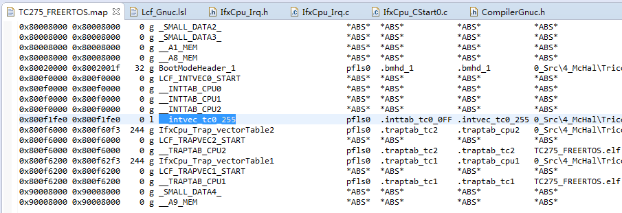
这里所定义的段.intvec_tc0_255,也就是中断向量,在链接的过程中会被加载到ROM,因为在.lsl中预定义了.intvec_tc0_0~255的所有段,该段会被加载到地址0x800F1FE0处,如下图所示。

和硬件管理中断一样,该中断向量中也存储了一段跳转指令,跳转到函数IfxCpu_Irq_intVecTable(),该函数根据CCPN(=PIPN)到IfxCpu_Irq_swIntVector(中断服务函数指针数组)中查找并执行对应的中断服务函数。所谓软件管理中的“软件”指的就是这个函数。
将该中断向量载入到ROM后,如何保证发生中断时一定会跳转到该向量?
——启动代码将该向量的地址存储到了BIV寄存器中,如下图所示。


BIV中存储了该中断向量的地址,但是CPU计算中断向量地址时用式addr = BIV OR (PIPN << n),计算因子中不是还包含PIPN吗,那或的结果不就变成另一个地址了吗?
答案是:不会。因为给该中断向量设置的地址是个“特殊”地址,之所以进行特殊设置,是为了屏蔽PIPN的作用。
中断向量地址的计算有三种方法,如下图所示。

这里说明一点,虽然第三种方式专门用于定义一个中断向量,但是我们并没有使用。我们设置BIV的值为0x800F1FE0(二进制10000000000011110001111111100000),如下图所示,BIV寄存器的最后一位VSS为0,因此实际上使用的是第一种方法:计算时addr = (PIPN << 5) OR BIV。这里没有按照上图中(a)所示,将BIV[12..5]全设为0,而是全设为1,这样就能够屏蔽PIPN的作用,使得无论中断的优先级是多少,都一并跳转到同一地址,即唯一的中断向量的地址。

另外说明一下通过VSS位来设置中断向量空间大小的原理。VSS的值决定了中断向量地址的计算方法,如下图所示。
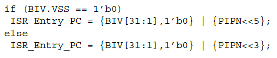
VSS为0时,计算时PIPN左移5位,使得相邻优先级的中断向量的地址之间相差0b100000,即32,也就是说使得每个中断向量拥有32字节大小的空间;当VSS为1时,计算时PIPN左移3位,使得相邻优先级的中断向量的地址之间相差0b1000,即8,然后也是同样的原理。这种设置主要用于硬件管理方式。相比之下,软件管理方式主要通过设置与PIPN做或运算的位段来实现唯一的中断向量地址
--------------------------------------------------------------------------------------------------------------------------------------------------------------------------------
三、两种中断管理方式的特点及两者的区别
两种管理方式最大的区别可归结为: 对BIV的使用方式不同。硬件管理方式用出了严格性与确定性,而软件管理方式则用了出灵活性。
参考文档:(1)TC297 User's Manual;(2)TC_Architecture_vol1_TC161_TCS_TC16P_TC16E