官方固件库中的对应函数为:
void SystemInit (void)
{
  /* Reset the RCC clock configuration to the default reset state(for debug purpose) */
  /* Set HSION bit */
  RCC->CR |= (uint32_t)0x00000001;

  /* Reset SW, HPRE, PPRE1, PPRE2, ADCPRE and MCO bits */
#ifndef STM32F10X_CL
  RCC->CFGR &= (uint32_t)0xF8FF0000;
#else
  RCC->CFGR &= (uint32_t)0xF0FF0000;
#endif /* STM32F10X_CL */

  /* Reset HSEON, CSSON and PLLON bits */
  RCC->CR &= (uint32_t)0xFEF6FFFF;

  /* Reset HSEBYP bit */
  RCC->CR &= (uint32_t)0xFFFBFFFF;

  /* Reset PLLSRC, PLLXTPRE, PLLMUL and USBPRE/OTGFSPRE bits */
  RCC->CFGR &= (uint32_t)0xFF80FFFF;

#ifdef STM32F10X_CL
  /* Reset PLL2ON and PLL3ON bits */
  RCC->CR &= (uint32_t)0xEBFFFFFF;

  /* Disable all interrupts and clear pending bits  */
  RCC->CIR = 0x00FF0000;

  /* Reset CFGR2 register */
  RCC->CFGR2 = 0x00000000;
#elif defined (STM32F10X_LD_VL) || defined (STM32F10X_MD_VL) || (defined STM32F10X_HD_VL)
  /* Disable all interrupts and clear pending bits  */
  RCC->CIR = 0x009F0000;

  /* Reset CFGR2 register */
  RCC->CFGR2 = 0x00000000;
#else
  /* Disable all interrupts and clear pending bits  */
  RCC->CIR = 0x009F0000;
#endif /* STM32F10X_CL */

#if defined (STM32F10X_HD) || (defined STM32F10X_XL) || (defined STM32F10X_HD_VL)
  #ifdef DATA_IN_ExtSRAM
    SystemInit_ExtMemCtl();
  #endif /* DATA_IN_ExtSRAM */
#endif

  /* Configure the System clock frequency, HCLK, PCLK2 and PCLK1 prescalers */
  /* Configure the Flash Latency cycles and enable prefetch buffer */
  SetSysClock();

#ifdef VECT_TAB_SRAM
  SCB->VTOR = SRAM_BASE | VECT_TAB_OFFSET; /* Vector Table Relocation in Internal SRAM. */
#else
  SCB->VTOR = FLASH_BASE | VECT_TAB_OFFSET; /* Vector Table Relocation in Internal FLASH. */
#endif
}

/**
  * @brief  Update SystemCoreClock variable according to Clock Register Values.
  *         The SystemCoreClock variable contains the core clock (HCLK), it can
  *         be used by the user application to setup the SysTick timer or configure
  *         other parameters.
  *
  * @note   Each time the core clock (HCLK) changes, this function must be called
  *         to update SystemCoreClock variable value. Otherwise, any configuration
  *         based on this variable will be incorrect.
  *
  * @note   - The system frequency computed by this function is not the real
  *           frequency in the chip. It is calculated based on the predefined
  *           constant and the selected clock source:
  *
  *           - If SYSCLK source is HSI, SystemCoreClock will contain the HSI_VALUE(*)
  *
  *           - If SYSCLK source is HSE, SystemCoreClock will contain the HSE_VALUE(**)
  *
  *           - If SYSCLK source is PLL, SystemCoreClock will contain the HSE_VALUE(**)
  *             or HSI_VALUE(*) multiplied by the PLL factors.
  *
  *         (*) HSI_VALUE is a constant defined in stm32f1xx.h file (default value
  *             8 MHz) but the real value may vary depending on the variations
  *             in voltage and temperature.
  *
  *         (**) HSE_VALUE is a constant defined in stm32f1xx.h file (default value
  *              8 MHz or 25 MHz, depedning on the product used), user has to ensure
  *              that HSE_VALUE is same as the real frequency of the crystal used.
  *              Otherwise, this function may have wrong result.
  *
  *         - The result of this function could be not correct when using fractional
  *           value for HSE crystal.
  * @param  None
  * @retval None
  */
首先第一眼就可以看到函数体中几乎全是条件编译。
(1.)先看第一行代码:RCC->CR |= (uint32_t)0x00000001;显然这是给CR寄存器的最低一位赋值为1.官方寄存器配置详解截图:


(2.)
#ifndef STM32F10X_CL
  RCC->CFGR &= (uint32_t)0xF8FF0000;
#else
  RCC->CFGR &= (uint32_t)0xF0FF0000;
#endif /* STM32F10X_CL */
这个条件编译是根据芯片容量不同默认初始化CFGR寄存器(Reset SW, HPRE, PPRE1, PPRE2, ADCPRE and MCO bits )。官方寄存器配置截图(各个位的信息太长,没有截取):

(3.)
 RCC->CR &= (uint32_t)0xFEF6FFFF;
 RCC->CR &= (uint32_t)0xFFFBFFFF;
显然是把CR寄存器的某些位赋值,其作用为:Reset HSEON, CSSON and PLLON ,HSEBYPbits即将HSEON,CSSON,PLLON,HSEBYP位置为零。
(4.)
/* Reset PLLSRC, PLLXTPRE, PLLMUL and USBPRE/OTGFSPRE bits */
  RCC->CFGR &= (uint32_t)0xFF80FFFF;
作用为把CFGR寄存器的PLLSRC, PLLXTPRE, PLLMUL and USBPRE/OTGFSPRE位置0
(5.)
#ifdef STM32F10X_CL
  /* Reset PLL2ON and PLL3ON bits */
  RCC->CR &= (uint32_t)0xEBFFFFFF;

  /* Disable all interrupts and clear pending bits  */
  RCC->CIR = 0x00FF0000;

  /* Reset CFGR2 register */
  RCC->CFGR2 = 0x00000000;
#elif defined (STM32F10X_LD_VL) || defined (STM32F10X_MD_VL) || (defined STM32F10X_HD_VL)
  /* Disable all interrupts and clear pending bits  */
  RCC->CIR = 0x009F0000;

  /* Reset CFGR2 register */
  RCC->CFGR2 = 0x00000000;
#else
  /* Disable all interrupts and clear pending bits  */
  RCC->CIR = 0x009F0000;
#endif /* STM32F10X_CL */
这个条件编译块的作用为根据芯片容量初始化中断位(关闭中断位)
(6.)
#if defined (STM32F10X_HD) || (defined STM32F10X_XL) || (defined STM32F10X_HD_VL)
  #ifdef DATA_IN_ExtSRAM
    SystemInit_ExtMemCtl();
  #endif /* DATA_IN_ExtSRAM */
#endif
这个条件编译块的作用为初始化Memory控制
(7.)
SetSysClock();
这里调用了一个函数,该函数为:
static void SetSysClock(void)
{
#ifdef SYSCLK_FREQ_HSE
  SetSysClockToHSE();
#elif defined SYSCLK_FREQ_24MHz
  SetSysClockTo24();
#elif defined SYSCLK_FREQ_36MHz
  SetSysClockTo36();
#elif defined SYSCLK_FREQ_48MHz
  SetSysClockTo48();
#elif defined SYSCLK_FREQ_56MHz
  SetSysClockTo56();
#elif defined SYSCLK_FREQ_72MHz
  SetSysClockTo72();
#endif

 /* If none of the define above is enabled, the HSI is used as System clock
    source (default after reset) */
}
我们可以看到该函数就是通过判断定义了哪个宏定义标志符而调用不同的设置sys时钟频率的函数,官方固件库默认定义了SYSCLK_FREQ_72MHz,所以会调用SetSysClockTo72这个函数。
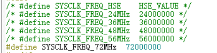
如果要使用其它频率,那就解开相应注释(只保留一个不被注释)。
SetSysClockTo72函数如下:
static void SetSysClockTo72(void)
{
  __IO uint32_t StartUpCounter = 0, HSEStatus = 0;

  /* SYSCLK, HCLK, PCLK2 and PCLK1 configuration ---------------------------*/
  /* Enable HSE */
  RCC->CR |= ((uint32_t)RCC_CR_HSEON);

  /* Wait till HSE is ready and if Time out is reached exit */
  do
  {
    HSEStatus = RCC->CR & RCC_CR_HSERDY;
    StartUpCounter++;
  } while((HSEStatus == 0) && (StartUpCounter != HSE_STARTUP_TIMEOUT));

  if ((RCC->CR & RCC_CR_HSERDY) != RESET)
  {
    HSEStatus = (uint32_t)0x01;
  }
  else
  {
    HSEStatus = (uint32_t)0x00;
  }

  if (HSEStatus == (uint32_t)0x01)
  {
    /* Enable Prefetch Buffer */
    FLASH->ACR |= FLASH_ACR_PRFTBE;

    /* Flash 2 wait state */
    FLASH->ACR &= (uint32_t)((uint32_t)~FLASH_ACR_LATENCY);
    FLASH->ACR |= (uint32_t)FLASH_ACR_LATENCY_2;


    /* HCLK = SYSCLK */
    RCC->CFGR |= (uint32_t)RCC_CFGR_HPRE_DIV1;

    /* PCLK2 = HCLK */
    RCC->CFGR |= (uint32_t)RCC_CFGR_PPRE2_DIV1;

    /* PCLK1 = HCLK */
    RCC->CFGR |= (uint32_t)RCC_CFGR_PPRE1_DIV2;

#ifdef STM32F10X_CL
    /* Configure PLLs ------------------------------------------------------*/
    /* PLL2 configuration: PLL2CLK = (HSE / 5) * 8 = 40 MHz */
    /* PREDIV1 configuration: PREDIV1CLK = PLL2 / 5 = 8 MHz */

    RCC->CFGR2 &= (uint32_t)~(RCC_CFGR2_PREDIV2 | RCC_CFGR2_PLL2MUL |
                              RCC_CFGR2_PREDIV1 | RCC_CFGR2_PREDIV1SRC);
    RCC->CFGR2 |= (uint32_t)(RCC_CFGR2_PREDIV2_DIV5 | RCC_CFGR2_PLL2MUL8 |
                             RCC_CFGR2_PREDIV1SRC_PLL2 | RCC_CFGR2_PREDIV1_DIV5);

    /* Enable PLL2 */
    RCC->CR |= RCC_CR_PLL2ON;
    /* Wait till PLL2 is ready */
    while((RCC->CR & RCC_CR_PLL2RDY) == 0)
    {
    }


    /* PLL configuration: PLLCLK = PREDIV1 * 9 = 72 MHz */
    RCC->CFGR &= (uint32_t)~(RCC_CFGR_PLLXTPRE | RCC_CFGR_PLLSRC | RCC_CFGR_PLLMULL);
    RCC->CFGR |= (uint32_t)(RCC_CFGR_PLLXTPRE_PREDIV1 | RCC_CFGR_PLLSRC_PREDIV1 |
                            RCC_CFGR_PLLMULL9);
#else
    /*  PLL configuration: PLLCLK = HSE * 9 = 72 MHz */
    RCC->CFGR &= (uint32_t)((uint32_t)~(RCC_CFGR_PLLSRC | RCC_CFGR_PLLXTPRE |
                                        RCC_CFGR_PLLMULL));
    RCC->CFGR |= (uint32_t)(RCC_CFGR_PLLSRC_HSE | RCC_CFGR_PLLMULL9);
#endif /* STM32F10X_CL */

    /* Enable PLL */
    RCC->CR |= RCC_CR_PLLON;

    /* Wait till PLL is ready */
    while((RCC->CR & RCC_CR_PLLRDY) == 0)
    {
    }

    /* Select PLL as system clock source */
    RCC->CFGR &= (uint32_t)((uint32_t)~(RCC_CFGR_SW));
    RCC->CFGR |= (uint32_t)RCC_CFGR_SW_PLL;

    /* Wait till PLL is used as system clock source */
    while ((RCC->CFGR & (uint32_t)RCC_CFGR_SWS) != (uint32_t)0x08)
    {
    }
  }
  else
  { /* If HSE fails to start-up, the application will have wrong clock
         configuration. User can add here some code to deal with this error */
  }
}
这个函数体比较长,但仔细看会发现这个函数就是在配置CR,CFGR,ACR(设置FLASH)寄存器的某些位(使能,判断是否就绪,设置相应位,设置FLASH,设置AHB,APB预分频系数,设置HCLK,PCLK等等外设时钟,设置PLL锁相环倍频系数最终确定系统时钟),结合官方注释和官方寄存器的说明很容易理解。
ps:
/* PCLK1 = HCLK */
    RCC->CFGR |= (uint32_t)RCC_CFGR_PPRE1_DIV2;
请注意官方备注有误,应备注为PCLK1 = HCLK/2
至此,SystemInit函数就能大概理解了。但是还有一个问题需要注意:那就是虽然我们在main函数中并没有调用SystemInit函数,但它在start up启动文件中被调用了:
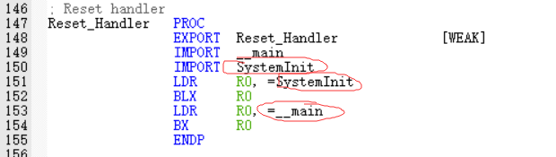
可以看到SystemInit函数是在main函数之前执行的,要是像自定义自己的SystemInit函数,那这里也要修改名称
