网络互联期末复习题
1.3.4.2 动态路由
R2路由器
cisco
enable
class
configure terminal
router rip
network 192.168.2.0
network 192.168.3.0
network 192.168.7.0
end
R3路由器
cisco
enable
class
configure terminal
router rip
network 192.168.3.0
network 192.168.4.0
network 192.168.5.0
exit
ip route 192.168.1.0 255.255.255.0 FastEthernet 0/0
R4路由器
cisco
enable
class
configure terminal
router rip
network 192.168.5.0
network 192.168.6.0
network 192.168.7.0
end
2.8.2.2 静态路由配置练习
因为要每个子网支持60台主机,所以至少需要6位作为主机位,共可以划分4个子网,分别为:
192.168.2.0/26
192.168.2.64/26
192.168.2.128/26
192.168.2.192/26
下面为拓扑网分配子网地址,题目要求为:
- 将子网 1 分配给连接到 HQ 的 LAN
- 将子网 2 分配给 HQ 和 BRANCH 之间的 WAN 链路
- 将子网 3 分配给连接到 BRANCH 的 LAN
- 子网 0 用于供将来扩展
为设备接口分配适当的地址。 - 将子网 1 中第一个有效主机地址分配给 HQ 上的 LAN 接口。
- 将子网 1 中最后一个有效主机地址分配给 PC2。
- 将子网 2 中第一个有效主机地址分配给 BRANCH 上的 WAN 接口。
- 将子网 2 中第二个有效主机地址分配给 HQ 上的 WAN 接口。
- 将子网 3 中第一个有效主机地址分配给 BRANCH 上的 LAN 接口。
- 将子网 3 中最后一个有效主机地址分配给 PC1。
| 设备 | 接口 | IP地址 | 子网掩码 | 默认网关 |
|---|---|---|---|---|
| BRANCH | Fa0/0 | 192.168.2.193 | 255.255.255.192 | N/A |
| BRANCH | S0/0/0 | 192.168.2.129 | 255.255.255.192 | N/A |
| HQ | Fa0/0 | 192.168.2.65 | 255.255.255.192 | N/A |
| HQ | S0/0/0 | 192.168.2.130 | 255.255.255.192 | N/A |
| HQ | S0/0/1 | 209.165.201.2 | 255.255.255.252 | N/A |
| ISP | Fa0/0 | 209.165.200.225 | 255.255.255.224 | N/A |
| ISP | S0/0/0 | 209.165.201.1 | 255.255.255.252 | N/A |
| PC1 | 网卡 | 192.168.2.254 | 255.255.255.192 | 192.168.2.193 |
| PC2 | 网卡 | 192.168.2.126 | 255.255.255.192 | 192.168.2.65 |
| Web服务器 | 网卡 | 209.165.200.254 | 255.255.255.224 | 209.165.200.225 |
按照上表中给各个设备设置IP地址、子网掩码以及默认网关,这里就不放过程了,直接配置就可以,对端口配置完IP后别忘了开启端口。配置完成后进行下一步
根据以下说明对 BRANCH、HQ 和 ISP 路由器进行基本配置:
- 配置路由器主机名
- 禁用 DNS 查找
- 配置执行模式口令
- 配置当天消息标题
- 为控制台连接配置口令
- 为 VTY 连接配置口令
HQ路由器:
enable
configure terminal
hostname HQ
no ip domain-lookup
enable password class
banner motd $
this is banner!$
line console 0
password cisco
login
exit
line vty 0 4
password cisco
Branch路由器
enable
configure terminal
hostname Branch
no ip domain-lookup
enable password class
banner motd $
this is banner!$
line console 0
password cisco
login
exit
line vty 0 4
password cisco
ISP路由器
enable
configure terminal
hostname ISP
no ip domain-lookup
enable password class
banner motd $
this is banner!$
line console 0
password cisco
login
exit
line vty 0 4
password cisco
下面配置静态路由:
Branch:
ip route 0.0.0.0 0.0.0.0 s0/0/0
HQ:
ip route 0.0.0.0 0.0.0.0 209.165.201.1
ip route 192.168.2.192 255.255.255.192 s0/0/0
ISP:
ip route 192.168.2.0 255.255.255.0 s0/0/0
7.5.2.2 RIPv2 练习配置实验(83/84)
任务 1:对地址空间划分子网。
步骤 1- 研究网络要求。
此网络的编址方案应满足以下要求:
-
ISP LAN 使用 209.165.200.224/27 网络。
-
ISP 和 HQ 之间的链路使用 209.165.202.128/27 网络。
-
必须使用 VLSM 对 192.168.40.0/24 网络划分子网,以供其它链路使用。
-
HQ LAN 1 需要 50 个主机 IP 地址。
-
HQ LAN 2 需要 50 个主机 IP 地址。
-
BRANCH LAN 1 需要 30 个主机 IP 地址。
-
BRANCH LAN 2 需要 12 个主机 IP 地址。
-
HQ 和 BRANCH 之间的链路两端各需要一个 IP 地址。
Step 2- 创建网络设计时请思考以下问题:
需要为 192.168.40.0/24 网络创建多少个子网?
5个
总共需要从 192.168.40.0/24 网络获得多少个 IP 地址?
100+30+12+2 = 144个
HQ LAN1 子网将使用什么子网掩码?
255.255.255.192
该子网可以使用的主机地址最多有多少个?
62个 192.168.40.1/26 ~ 192.168.40.62/26
HQ LAN2 子网将使用什么子网掩码?
255.255.255.192
该子网可以使用的主机地址最多有多少个?
62个 192.168.40.65/26 ~ 192.168.40.126/26
BRANCH LAN1 子网将使用什么子网掩码?
255.255.255.224
该子网可以使用的主机地址最多有多少个?
30个 192.168.40.129/27 ~ 192.168.40.158/27
BRANCH LAN2 子网将使用什么子网掩码?
255.255.255.240
该子网可以使用的主机地址最多有多少个?
14个 192.168.40.161/28 ~ 192.168.40.174/28
HQ 和 BRANCH 路由器之间的链路将使用什么子网掩码?
255.255.255.252
该子网可以使用的主机地址最多有多少个?
2个 192.168.40.177/30 ~ 192.168.40.178/30
任务 2:确定接口地址。
步骤 1- 为设备接口分配适当的地址
将 209.165.200.224/27 网络中的第一个有效主机地址分配给 ISP 路由器上的 LAN 接口。
209.165.200.225/27
将 209.165.200.224/27 网络中的最后一个有效主机地址分配给 PC5
209.165.200.254/27
将 209.165.202.128/27 网络中的第一个有效主机地址分配给 ISP 的 WAN 接口。
209.165.202.129/27
将 209.165.202.128/27 网络中的最后一个有效主机地址分配给 HQ 的 Serial 0/0/1 接口。
209.165.202.158/24
将 HQ LAN1 网络中的第一个有效主机地址分配给 HQ 的 LAN1 接口。
192.168.40.1/26
将 HQ LAN1 网络中的最后一个有效主机地址分配给 PC3。
192.168.40.62/26
将 HQ LAN2 网络中的第一个有效主机地址分配给 HQ 的 LAN2 接口。
192.168.40.65/26
将 HQ LAN2 网络中的最后一个有效主机地址分配给 PC 4。
192.168.40.126/26
将 HQ/BRANCH WAN 链路中的第一个有效主机地址分配给 HQ 的 Serial 0/0/0 接口。
192.168.40.177/30
将 HQ/BRANCH WAN 链路中的最后一个有效主机地址分配给 BRANCH 的 Serial 0/0/0 接口。
192.168.40.178/30
将 BRANCH LAN1 网络中的第一个有效主机地址分配给 BRANCH 的 LAN1 接口。
192.168.40.129/27
将 BRANCH LAN1 网络中的最后一个有效主机地址分配给 PC1。
192.168.40.174/28
将 BRANCH LAN2 网络中的第一个有效主机地址分配给 BRANCH 的 LAN2 接口。
192.168.40.161/28
将 BRANCH LAN2 网络中的最后一个有效主机地址分配给 PC 2
分配IP地址
192.168.40.158/27
任务 3:准备网络
步骤 1- 使用本练习中的图表和现有设备进行网络布线。
拓补图为:
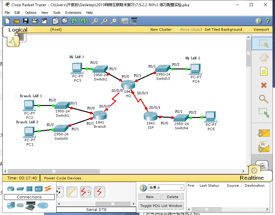
任务 4:执行基本路由器配置。
-
根据以下说明对 BRANCH、HQ 和 ISP 路由器进行基本配置:
-
配置路由器主机名。
-
禁用 DNS 查找。
-
配置执行模式口令。
-
配置当日消息标语。
-
配置控制台连接的口令。
-
配置 VTY 连接的口令。
HQ路由器:
enable
configure terminal
hostname Branch
no ip domain-lookup
enable password class
banner motd $
this is banner!$
line console 0
password cisco
login
exit
line vty 0 4
password cisco
Branch路由器
enable
configure terminal
hostname Branch
no ip domain-lookup
enable password class
banner motd $
this is banner!$
line console 0
password cisco
login
exit
line vty 0 4
password cisco
ISP路由器
enable
configure terminal
hostname ISP
no ip domain-lookup
enable password class
banner motd $
this is banner!$
line console 0
password cisco
login
exit
line vty 0 4
password cisco
任务 5:配置并激活串行地址和以太网地址。
步骤 1 - 配置 BRANCH、HQ 和 ISP 路由器。
使用拓扑图下方地址表中的 IP 地址配置 BRANCH、HQ 和 ISP 上的接口。
完成后,务必将运行配置保存到路由器的 NVRAM 中。
步骤 2 - 配置 PC1、PC2、PC3、PC4 和 PC5 的以太网接口。
使用拓扑图下方地址表中的 IP 地址配置 PC1、PC2、PC3、PC4 和 PC5 的以太网接口。
各设备IP地址为:
| 设备 | 接口 | IP地址 | 子网掩码 | 默认网关 |
|---|---|---|---|---|
| ISP | F0/0 | 209.165.200.225 | 255.255.255.224 | N/A |
| ISP | S0/0/1 | 209.165.202.129 | 255.255.255.224 | N/A |
| HQ | F0/0 | 192.168.40.1 | 255.255.255.192 | N/A |
| HQ | F0/1 | 192.168.40.65 | 255.255.255.192 | N/A |
| HQ | S0/0/0 | 192.168.40.177 | 255.255.255.252 | N/A |
| HQ | S0/0/1 | 209.165.202.158 | 255.255.255.0 | N/A |
| Branch | F0/0 | 192.168.40.129 | 255.255.255.224 | N/A |
| Branch | F0/1 | 192.168.40.161 | 255.255.255.240 | N/A |
| Branch | S0/0/0 | 192.168.40.178 | 255.255.255.252 | N/A |
| PC1 | 网卡 | 192.168.40.174 | 255.255.255.240 | 192.168.40.161 |
| PC2 | 网卡 | 192.168.40.158 | 255.255.255.224 | 192.168.40.129 |
| PC3 | 网卡 | 192.168.40.62 | 255.255.255.192 | 192.168.40.1 |
| PC4 | 网卡 | 192.168.40.126 | 255.255.255.192 | 192.168.40.65 |
| PC5 | 网卡 | 209.165.200.254 | 255.255.255.224 | 209.165.200.225 |
Branch、HQ、ISP的时钟配置:
interface serial 0/0/0
clock rate 56000
exit
interface serial 0/0/1
clock rate 56000
exit
任务 7:在 BRANCH 路由器上配置 RIPv2 路由。
router rip
version 2
no auto-summary
network 192.168.40.128
network 192.168.40.160
network 192.168.40.176
passive-interface fastEthernet 0/0
passive-interface fastEthernet 0/1
任务 8:在 HQ 上配置 RIPv2 和静态路由。
ip route 0.0.0.0 0.0.0.0 serial 0/0/1
router rip
version 2
no auto-summary
network 192.168.40.0
network 192.168.40.64
network 192.168.40.128
network 192.168.40.160
network 192.168.40.176
network 209.165.202.128
passive-interface fastEthernet 0/0
passive-interface fastEthernet 0/1
default-information originate
任务 9:在 ISP 路由器上配置静态路由。
ip route 192.168.40.0 255.255.255.0 serial 0/0/1
练习 3.5.2.2 VLAN 配置练习(73/74)
地址表
| 设设备 | 接口 | IP 地址 | 子网掩码 | 默认网关 |
|---|---|---|---|---|
| S1 | VLAN | 56 192.168.56.11 | 255.255.255.0 | 不适用 |
| S2 | VLAN | 56 192.168.56.12 | 255.255.255.0 | 不适用 |
| S3 | VLAN | 56 192.168.56.13 | 255.255.255.0 | 不适用 |
| PC1 | 网卡 | 192.168.10.21 | 255.255.255.0 | 192.168.10.1 |
| PC2 | 网卡 | 192.168.20.22 | 255.255.255.0 | 192.168.20.1 |
| PC3 | 网卡 | 192.168.30.23 | 255.255.255.0 | 192.168.30.1 |
| PC4 | 网卡 | 192.168.10.24 | 255.255.255.0 | 192.168.10.1 |
| PC5 | 网卡 | 192.168.20.25 | 255.255.255.0 | 192.168.20.1 |
| PC6 | 网卡 | 192.168.30.26 | 255.255.255.0 | 192.168.30.1 |
端口分配(交换机 2 和 3)
| 端口 | 分配 | 网络 |
|---|---|---|
| Fa0/1-0/5 | VLAN 56 - Management&Native | 192.168.56.0 /24 |
| Fa0/6-0/10 | VLAN 30 - Guest(Default) | 192.168.30.0 /24 |
| Fa0/11 - 0/17 | VLAN 10 - Faculty/Staff | 192.168.10.0 /24 |
| Fa0/18 - 0/24 | VLAN 20 - Students | 192.168.20.0 /24 |
任务 1:执行基本交换机配置
根据以下指导原则配置交换机。Packet Tracer 只对主机名评分。
配置交换机主机名。
禁用 DNS 查找。
将执行模式口令配置为 class。
为控制台连接配置口令 cisco。
为 vty 连接配置口令 cisco。
S1:
enable
configure terminal
hostname S1
no ip domain-lookup
enable secret class
banner motd $
this is banner!$
line console 0
password cisco
login
exit
line vty 0 4
password cisco
S2:
enable
configure terminal
hostname S2
no ip domain-lookup
enable secret class
banner motd $
this is banner!$
line console 0
password cisco
login
exit
line vty 0 4
password cisco
S3:
enable
configure terminal
hostname S3
no ip domain-lookup
enable secret class
banner motd $
this is banner!$
line console 0
password cisco
login
exit
line vty 0 4
password cisco
任务 2:配置并激活以太网接口
步骤 1. 配置 PC。
使用本练习开头部分地址表中的 IP 地址和默认网关配置六台 PC 的以太网接口。现在 PC1 的 IP 地址会评定为错误。您将在稍后的练习中更改 PC1 的地址。
步骤 2. 在 S2 和 S3 上启用提供访问的用户端口。
任务 3:在交换机上配置 VLAN
步骤 1. 在交换机 S1 上创建 VLAN。
VLAN ID 和名称列在本练习开头部分的端口分配表中。
步骤 2. 检验在 S1 上创建的 VLAN。
步骤 3. 在交换机 S2 和 S3 上配置、命名和检验 VLAN。
步骤 4. 在 S2 和 S3 上将交换机端口分配给 VLAN。
注意:S2 Fa0/11 端口现在会被评为错误,并且 Packet Tracer 将只对每个 VLAN 的第一个端口分配评分。
步骤 5. 确定 S2 的哪些端口已添加到 VLAN 10。
步骤 6. 在每台交换机上配置管理 VLAN 56。
步骤1 - 6:
S1
vlan 56
name Management&Native
exit
vlan 30
name Guest(Default)
exit
vlan 10
name Faculty/Staff
exit
vlan 20
name Students
exit
interface range fastEthernet 0/1 -5
switchport access vlan 56
exit
interface range fastEthernet 0/6 -10
switchport access vlan 30
exit
interface range fastEthernet 0/11 -17
switchport access vlan 10
exit
interface range fastEthernet 0/18 -24
switchport access vlan 20
exit
interface vlan 56
ip address 192.168.56.11 255.255.255.0
S2:
vlan 56
name Management&Native
exit
vlan 30
name Guest(Default)
exit
vlan 10
name Faculty/Staff
exit
vlan 20
name Students
exit
interface range fastEthernet 0/1 -5
switchport access vlan 56
exit
interface range fastEthernet 0/6 -10
switchport access vlan 30
exit
interface range fastEthernet 0/11 -17
switchport access vlan 10
exit
interface range fastEthernet 0/18 -24
switchport access vlan 20
exit
interface vlan 56
ip address 192.168.56.12 255.255.255.0
S3:
vlan 56
name Management&Native
exit
vlan 30
name Guest(Default)
exit
vlan 10
name Faculty/Staff
exit
vlan 20
name Students
exit
interface range fastEthernet 0/1 -5
switchport access vlan 56
exit
interface range fastEthernet 0/6 -10
switchport access vlan 30
exit
interface range fastEthernet 0/11 -17
switchport access vlan 10
exit
interface range fastEthernet 0/18 -24
switchport access vlan 20
exit
interface vlan 56
ip address 192.168.56.13 255.255.255.0
步骤 7. 为所有三台交换机上的中继端口配置中继和本征 VLAN。检验中继配置情况。
S1:
interface fastEthernet 0/1
switchport mode trunk
switchport trunk native vlan 56
exit
interface fastEthernet 0/2
switchport mode trunk
switchport trunk native vlan 56
exit
S2:
interface fastEthernet 0/1
switchport mode trunk
switchport trunk native vlan 56
exit
interface fastEthernet 0/11
switchport mode access
exit
interface fastEthernet 0/18
switchport mode access
exit
interface fastEthernet 0/6
switchport mode access
exit
S3:
interface fastEthernet 0/2
switchport mode trunk
switchport trunk native vlan 56
exit
interface fastEthernet 0/11
switchport mode access
exit
interface fastEthernet 0/18
switchport mode access
exit
interface fastEthernet 0/6
switchport mode access
exit
步骤 8. 检验 S1、S2 和 S3 是否能够通信。
步骤 9. 从 PC2 ping 其它主机。结果是什么?
步骤 10. 将 PC1 移到与 PC2 相同的 VLAN 中。PC1 是否能 ping 通 PC2?
步骤 11. 将 PC1 的 IP 地址更改为 192.168.20.21。PC1 是否能 ping 通 PC2?
练习 4.4.2:VTP 配置(117/120)
地址表
| 设备 | 接口 | IP 地址 | 子网掩码 |
|---|---|---|---|
| S1 | VLAN 99 | 172.31.99.11 | 255.255.255.0 |
| S2 | VLAN 99 | 172.31.99.12 | 255.255.255.0 |
| S3 | VLAN 99 | 172.31.99.13 | 255.255.255.0 |
| PC1 | 网卡 | 172.31.10.1 | 255.255.255.0 |
| PC2 | 网卡 | 172.31.20.1 | 255.255.255.0 |
| PC3 | 网卡 | 172.31.30.1 | 255.255.255.0 |
| PC4 | 网卡 | 172.31.10.2 | 255.255.255.0 |
| PC5 | 网卡 | 172.31.20.2 | 255.255.255.0 |
| PC6 | 网卡 | 172.31.30.2 | 255.255.255.0 |
端口分配(S2 和 S3)
| 端口 | 分配 | 网络 |
|---|---|---|
| Fa0/1 - 0/5 | 802.1q 中继 | |
| Fa0/6 - 0/10 | VLAN 30 - Administration | 172.31.30.0 /24 |
| Fa0/11 - 0/17 | VLAN 10 - Engineering | 172.31.10.0 /24 |
| Fa0/18 - 0/24 | VLAN 20 - Sales | 172.31.20.0 /24 |
| 无 | VLAN 99 - Network Mgmt | 172.31.99.0 /24 |
任务 1:执行基本交换机配置
根据以下原则配置交换机 S1、S2 和 S3 并保存配置:
按照拓扑所示配置交换机主机名。
禁用 DNS 查找。
将执行模式口令配置为 class。
将控制台和 vty 连接口令配置为 cisco。
S1:
enable
configure terminal
hostname S1
no ip domain-lookup
enable secret class
banner motd $
this is banner!$
line console 0
password cisco
login
exit
line vty 0 4
password cisco
S2:
enable
configure terminal
hostname S2
no ip domain-lookup
enable secret class
banner motd $
this is banner!$
line console 0
password cisco
login
exit
line vty 0 4
password cisco
S3:
enable
configure terminal
hostname S3
no ip domain-lookup
enable secret class
banner motd $
this is banner!$
line console 0
password cisco
login
exit
line vty 0 4
password cisco
任务 2:配置主机 PC 上的以太网接口
使用地址表中的 IP 地址配置 PC1、PC2、PC3、PC4、PC5 和 PC6 的以太网接口。本练习无需配置默认网关。
按照IP地址配置即可
任务 3:在交换机上配置 VTP
VTP 可让网络管理员通过创建 VTP 域来控制网络上的 VLAN 实例。在每个 VTP 域中,可以将一台或多台交换机配置为 VTP 服务器。然后可以在 VTP 服务器上创建 VLAN,并将这些 VLAN 传送给域中的其它交换机。常见的 VTP 配置任务是设置工作模式、域和口令。在本实验中,您将把 S1 配置为 VTP 服务器,并将 S2 和 S3 配置为 VTP 客户端。
步骤 1. 检查三台交换机上的当前 VTP 配置。
步骤 2. 在所有三台交换机上配置工作模式、域名和 VTP 口令。
在三台交换机上,全部将 VTP 域名设置为 access,VTP 口令设置为 lab4。将 S1 配置为服务器模式,S2 配置为客户端模式,S3 配置为透明模式。Packet Tracer 开始时会将 S3 的模式评定为不正确。您需要在本练习的后面部分对此加以更正。
注意:客户端交换机可从服务器交换机处获知 VTP 域名,但前提是客户端交换机的域为空。如果客户端交换机已设置有域名,则不会获知新的域名。因此,最好是在所有交换机上手动配置域名,以确保域名配置正确。位于不同 VTP 域中的交换机不会交换 VLAN 信息。
步骤1-2:
S1:
configure terminal
vtp mode server
vtp domain access
vtp password lab4
S2:
configure terminal
vtp mode client
vtp domain access
vtp password lab4
S3:
configure terminal
vtp mode transparent
vtp domain access
vtp password lab4
步骤 3. 为所有三台交换机上的中继端口配置中继和本征 VLAN。
在所有交换机上,为 FastEthernet 接口 0/1-5 配置中继和本征 VLAN。
S1:
S1(config)#interface range fastEthernet 0/1-5
S1(config-if-range)#switchport mode trunk
S1(config-if)#switchport trunk native vlan 99
S1(config-if)#no shutdown
S2:
interface range fastEthernet 0/1-5
switchport mode trunk
switchport trunk native vlan 99
no shutdown
S3:
interface range fastEthernet 0/1-5
switchport mode trunk
switchport trunk native vlan 99
no shutdown
步骤 4. 在 S2 和 S3 接入层交换机上配置端口安全功能。
配置 S2 和 S3 上的端口 fa0/6、fa0/11 和 fa0/18,使它们最多允许两台主机连接到这些端口上,并使它们能动态获知主机的 MAC 地址。
S2:
S2(config)#interface range fastEthernet 0/6,fa0/11,fa0/18
S2(config-if-range)#switchport port-security maximum 2
S2(config-if-range)#switchport port-security mac-address sticky
S2(config-if-range)#switchport port-security violation shutdown
S3:
interface range fastEthernet 0/6,fa0/11,fa0/18
switchport port-security maximum 2
switchport port-security mac-address sticky
switchport port-security violation shutdown
步骤 5. 在 VTP 服务器上配置 VLAN。
本实验需要四个 VLAN:
VLAN 99 management
VLAN 10 engineering
VLAN 20 sales
VLAN 30 administration
在 VTP 服务器上配置这些 VLAN。
完成后,检验 S1 上是否创建了所有四个 VLAN。
S1:
VLAN 99
name management
exit
VLAN 10
name engineering
exit
VLAN 20
name sales
exit
VLAN 30
name administration
exit
(如果S2,S3最后没获取到,可以手动设置)
步骤 6. 检查 S1 上创建的 VLAN 是否已分发给 S2 和 S3。
在 S2 和 S3 上使用 show vlan brief 命令检查 VTP 服务器是否已将其 VLAN 配置传送给所有的交换机。
所有交换机上配置的 VLAN 都相同吗?
为什么 S2 和 S3 具有不同的 VLAN 配置?
步骤 7. 在所有三台交换机上配置管理接口地址。
在继续操作之前,先将 S3 上的 VTP 模式更改为客户端。然后检验 S3 是否已通过 VTP 收到来自 S1 的 VLAN 配置。
使用本练习开头部分提供的地址表中的 IP 地址配置所有三台交换机。将这些地址分配给网络管理 VLAN (VLAN 99)。
在交换机之间执行 ping 操作,检查这些交换机是否都已得到正确配置。从 S1 ping S2 和 S3 的管理接口。从 S2 ping S3 的管理接口。
ping 是否成功?若不成功,则找出交换机配置问题并解决。
S1:
interface vlan 99
ip address 172.31.99.11 255.255.255.0
no shutdown
S2:
interface vlan 99
ip address 172.31.99.12 255.255.255.0
no shutdown
S3:
interface vlan 99
ip address 172.31.99.13 255.255.255.0
no shutdown
步骤 8. 分配交换机端口给 VLAN。
请参阅本实验开头的端口分配表,将端口分配给 VLAN。请注意,端口分配不是通过 VTP 配置的。请记住,交换机 S2 和 S3 的配置方法相似。完成后保存配置。
S2、S3:
interface range fastEthernet 0/6-10
switchport mode access
switchport access vlan 30
exit
interface range fastEthernet 0/11 -17
switchport mode access
switchport access vlan 10
exit
interface range fastEthernet 0/18-24
switchport mode access
switchport access vlan 20
exit
步骤 9. 检验中继是否工作正常。
在 PC1 上 ping PC4、PC5 和 PC6。
有成功的 ping 操作吗?
为什么有些 ping 失败了?
可以从 PC3 到达哪些主机?
练习 6.2.2.5 配置单臂路由器 VLAN 间路由
地址表
| 设备 | 接口 | IP 地址 | 子网掩码 | 默认网关 |
|---|---|---|---|---|
| R1 | Fa0/1.10 | 172.17.10.1 | 255.255.255.0 | 不适用 |
| Fa0/1.30 | 172.17.30.1 | 255.255.255.0 | 不适用 | |
| PC1 | 网卡 | 172.17.10.10 | 255.255.255.0 | 172.17.10.1 |
| PC2 | 网卡 | 172.17.30.10 | 255.255.255.0 | 172.17.30.1 |
任务 1:测试不使用 VLAN 间路由时的连通性
步骤 1. 在 PC1 和 PC3 之间执行 Ping 操作。
等待交换机收敛。在连接到 PC1 和 PC3 的交换机上,链路灯从琥珀色变为绿色。当链路灯呈绿色时,在 PC1 和 PC3之间执行 ping 操作。由于两台计算机位于不同网络中而且尚未配置路由器,因此它们无法相互通信,ping 操作会失败。
步骤 2. 切换到模拟模式监控 ping 操作。
单击 Simulation(模拟) 选项卡或按 Shift+S,切换到模拟模式。
单击 Capture/Forward(捕获/转发),观看 ping 操作在 PC1 和 PC3 之间采取的步骤。
请留意,ping 甚至无法经过交换机。
完成比例应为 0%。
任务 2:添加 VLAN
步骤 1. 在 S1 上创建 VLAN。
在 S1 上创建 VLAN 10 和 VLAN 30。PC1 属于 VLAN 10,PC3 属于 VLAN 30。 要创建 VLAN,请在全局配置模式下发出命令 vlan 10 和 vlan 30。
S1#configure terminal
S1(config)#vlan 10
S1(config-vlan)#vlan 30
要检查是否已创建 VLAN,请在特权执行提示符后发出 show vlan brief 命令。
步骤 2. 为端口分配 VLAN。
将交换机上的每个端口分配到 VLAN 以实现 VLAN 间通信。 Fa0/11 接口属于 VLAN 10,Fa0/6 接口属于 VLAN 30。
要为端口分配 VLAN,需进入接口配置模式。Fa0/11 的命令是 interface fa0/11。switchport mode access 命令可将该端口设置为接入模式。switchport access vlan 10 命令用于将 VLAN 10 分配给该端口。
S1(config)#interface fa0/11
S1(config-if)#switchport mode access
S1(config-if)#switchport access vlan 10
对 VLAN 30 的 Fa0/6 接口重复上述步骤。
S1(config)#interface fa0/6
S1(config-if)#switchport mode access
S1(config-if)#switchport access vlan 30
将 S1 的 Fa0/5 端口设置为中继端口,使其传输来自 VLAN 10 和 VLAN 30 的流量。 从 Fa0/5 接口发出 switchport mode trunk 命令,将该端口设置为中继端口。
Packet Tracer 不对此命令评分,但配置 VLAN 间路由时需要使用此命令。
S1(config)#interface fa0/5
S1(config-if)#switchport mode trunk
步骤 3. 测试 PC1 和 PC3之间的连通性。
现在,请在 PC1 和 PC3之间发出 ping 命令。ping 仍应失败。
步骤 4. 检查结果。
完成比例应为 27%。如果并非如此,请单击 Check Results(检查结果)查看尚未完成哪些必要部分
任务 3:配置 IP 地址
步骤 1. 使用 802.1Q 封装配置子接口。
在 R1 上创建两个子接口:Fa0/1.10 和 Fa0/1.30。将这两个子接口分配到不同的 VLAN。要创建第一个子接口,请发出 interface fa0/1.10 命令进入 Fa0/1.10 的子接口配置模式。请留意,路由器的命令提示符会更改。
在子接口配置模式下发出 encapsulation dot1Q 10 命令,将封装类型设置为 802.1Q 并将 VLAN 10 分配给该虚拟接口。
为端口分配正确的 IP 地址。Fa0/1.10 的 IP 地址应为 172.17.10.1,子网掩码为 255.255.255.0。使用正确的 IP 地址和 VLAN ID 对 Fa0/1.30 接口重复上述步骤。
R1(config)#interface fa0/1.10
R1(config-subif)#encapsulation dot1Q 10
R1(config-subif)#ip address 172.17.10.1 255.255.255.0
R1(config)#interface fa0/1.30
R1(config-subif)#encapsulation dot1Q 30
R1(config-subif)#ip address 172.17.30.1 255.255.255.0
步骤 2. 检查结果。
完成比例应为 100%。如果并非如此,请单击 Check Results(检查结果)查看尚未完成哪些必要部分。
任务 4:再次测试连通性
步骤 1. 在 PC1 和 PC3 之间执行 Ping 操作。
从 PC1 ping PC3。ping 应该会成功。
步骤 2. 切换到模拟模式监控 ping 操作。
单击 Simulation(模拟) 选项卡或按 Shift+S,切换到模拟模式。
单击 Capture/Forward(捕获/转发),观看 ping 操作在 PC1 和 PC3 之间采取的步骤。
观察 ping 如何从 PC1 首先到 S1,然后到 R1,再返回 S1,最终返回 PC3。
练习 5.2.8:配置标准 ACL
练习 5.2.8:配置标准 ACL
任务 2:评估网络策略并规划 ACL 实施
步骤 1. 评估 R1 LAN 的策略。
允许 192.168.10.0/24 网络访问除 192.168.11.0/24 网络外的所有位置。
允许 192.168.11.0/24 网络访问所有目的地址,连接到 ISP 的所有网络除外。
步骤 2. 为 R1 LAN 规划 ACL 实施。
用两个 ACL 可完全实施 R1 LAN 的安全策略。
在 R1 上配置第一个 ACL,拒绝从 192.168.10.0/24 网络发往 192.168.11.0/24 网络的流量,但允许所有其它流量。
此 ACL 应用于 R1 Fa0/1 接口的出站流量,监控发往 192.168.11.0 网络的所有流量。
在 R2 上配置第二个 ACL,拒绝 192.168.11.0/24 网络访问 ISP,但允许所有其它流量。
控制 R2 S0/1/0 接口的出站流量。
ACL 语句的顺序应该从最具体到最概括。拒绝网络流量访问其它网络的语句应在允许所有其它流量的语句之前。
S1:
access-list 10 deny 192.168.10.0 0.0.0.255
access-list 10 permit any
interface fastEthernet 0/1
ip access-group 10 out
S2:
access-list 11 deny 192.168.11.0 0.0.0.255
access-list 11 permit any
interface serial 0/1/0
ip access-group 11 out
步骤 3. 评估 R3 LAN 的策略。
允许 192.168.30.0/10 网络访问所有目的地址。
拒绝主机 192.168.30.128 访问 LAN 以外的地址。
步骤 4. 为 R3 LAN 规划 ACL 实施。
一个 ACL 即可完全实施 R3 LAN 的安全策略。
在 R3 上配置该 ACL,拒绝 192.168.30.128 主机访问 LAN 以外的地址,但允许 LAN 中的所有其它主机发出的流量。
此 ACL 将应用于 Fa0/0 接口的入站流量,监控尝试离开 192.168.30.0/10 网络的所有流量。
ACL 语句的顺序应该从最具体到最概括。拒绝 192.168.30.128 主机访问的语句应在允许所有其它流量的语句之前。
R3:
ip access-list standard NO_ACCESS
deny host 192.168.30.128
permit any
exit
interface fastEthernet 0/0
ip access-group NO_ACCESS in
