华为设备BGP路由技术
说明:
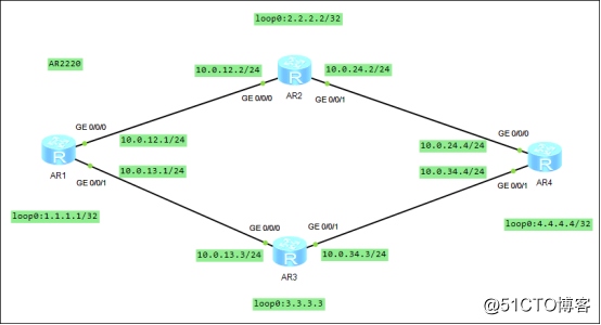
1:R1为运营商的路由器,R2、R3、R4为公司网络,所有路由器运行BGP路由协议
2:R1和R2之间、R1和R3之间都建立EBGP连接
3:R2、R3、R4之间建立IBGP全连接
4:运营商网络为AS100,公司网络为AS200
5:在AS200内,使用IGP协议来计算路由(IGB使用OSPF协议)
要求:
1:实现两个AS之间的互通
2:通过修改BGP属性实现业务需求的路径从R2切换到R3
实验步骤:
一:基础配置
1:配置各个设备的ip地址
(1)R1
<Huawei>sys
[Huawei]sysname R1
[R1]int g0/0/0
[R1-GigabitEthernet0/0/0]ip add 10.0.12.1 24
[R1-GigabitEthernet0/0/0]undo shut
[R1-GigabitEthernet0/0/0]int g0/0/1
[R1-GigabitEthernet0/0/1]ip add 10.0.13.1 24
[R1-GigabitEthernet0/0/1]undo shut
[R1-GigabitEthernet0/0/1]int loop0
[R1-LoopBack0]ip add 1.1.1.1 32
[R1-LoopBack0]quit
[R1]
(2)R2
<Huawei>sys
[Huawei]sysname R2
[R2]int g0/0/0
[R2-GigabitEthernet0/0/0]ip add 10.0.12.2 24
[R2-GigabitEthernet0/0/0]int g0/0/1
[R2-GigabitEthernet0/0/1]ip add 10.0.24.2 24
[R2-GigabitEthernet0/0/1]int loop0
[R2-LoopBack0]ip add 2.2.2.2 32
[R2-LoopBack0]quit
[R2]
(3)R3
<Huawei>sys
[Huawei]sysname R3
[R3]int g0/0/0
[R3-GigabitEthernet0/0/0]ip add 10.0.13.3 24
[R3-GigabitEthernet0/0/0]int g0/0/1
[R3-GigabitEthernet0/0/1]ip add 10.0.34.3 24
[R3-GigabitEthernet0/0/1]int loop0
[R3-LoopBack0]ip add 3.3.3.3 32
[R3-LoopBack0]quit
[R3]
(4)R4
<Huawei>sys
[Huawei]sysname R4
[R4]int g0/0/0
[R4-GigabitEthernet0/0/0]ip add 10.0.24.4 24
[R4-GigabitEthernet0/0/0]undo shut
[R4-GigabitEthernet0/0/0]int g0/0/1
[R4-GigabitEthernet0/0/1]ip add 10.0.34.4 24
[R4-GigabitEthernet0/0/1]undo shut
[R4-GigabitEthernet0/0/1]int loop0
[R4-LoopBack0]ip add 4.4.4.4 32
[R4-LoopBack0]quit
[R4]
二:配置公司网络的OSPF协议,使公司内网可以互访
1:R2
[R2]ospf 1
[R2-ospf-1]area 0
[R2-ospf-1-area-0.0.0.0]network 10.0.24.0 0.0.0.255
[R2-ospf-1-area-0.0.0.0]network 2.2.2.2 0.0.0.0
[R2-ospf-1-area-0.0.0.0]quit
[R2-ospf-1]quit
2:R3
[R3]ospf 1
[R3-ospf-1]area 0
[R3-ospf-1-area-0.0.0.0]network 10.0.34.0 0.0.0.255
[R3-ospf-1-area-0.0.0.0]network 3.3.3.3 0.0.0.0
[R3-ospf-1-area-0.0.0.0]quit
[R3-ospf-1]quit
3:R4
[R4]ospf 1
[R4-ospf-1]area 0
[R4-ospf-1-area-0.0.0.0]network 10.0.24.0 0.0.0.255
[R4-ospf-1-area-0.0.0.0]network 10.0.34.0 0.0.0.255
[R4-ospf-1-area-0.0.0.0]network 4.4.4.4 0.0.0.0
[R4-ospf-1-area-0.0.0.0]quit
[R4-ospf-1]quit
4:测试
R2、R3、R4互相ping以下他们的loopback地址,要能ping通
三:配置R1和R2、R1和R3之间的邻接关系,使他们之间能通过EBGP相互传递路由,在R2、R3和R4上配置IBGP邻接关系,使R2、R3、R4之间可以通过IBGP互相传递路由。
1:R1的配置
<R1>sys
[R1]bgp 100
[R1-bgp]router-id 1.1.1.1
[R1-bgp]peer 10.0.12.2 as-number 200
[R1-bgp]peer 10.0.13.3 as-number 200
[R1-bgp]network 1.1.1.1 32
2:R2的配置
[R2]bgp 200
[R2-bgp]router-id 2.2.2.2
[R2-bgp]peer 10.0.12.1 as-number 100
[R2-bgp]peer 10.0.24.4 as-number 200
[R2-bgp]peer 10.0.24.4 next-hop-local
[R3-bgp]import-route ospf 1
3:R3的配置
[R3]bgp 200
[R3-bgp]router-id 3.3.3.3
[R3-bgp]peer 10.0.13.1 as-number 100
[R3-bgp]peer 10.0.34.4 as-number 200
[R3-bgp]peer 10.0.34.4 next-hop-local
[R3-bgp]import-route ospf 1
4:R4的配置
<R4>sys
[R4]bgp 200
[R4-bgp]router-id 4.4.4.4
[R4-bgp]peer 10.0.24.2 as-number 200
[R4-bgp]peer 10.0.34.3 as-number 200
[R4-bgp]network 4.4.4.4 32
[R4-bgp]quit
[R4]
5:查看BGP路由
(1)R1的路由表
[R1]dis bgp routing-table
> 1.1.1.1/32 0.0.0.0 0 0 i
> 4.4.4.4/32 10.0.12.2 0 200i
- 10.0.13.3 0 200i
(2)R4的路由表
[R4]dis bgp routing-table
*>i 1.1.1.1/32 10.0.24.2 0 100 0 100i
- i 10.0.34.3 0 100 0 100i
*> 4.4.4.4/32 0.0.0.0 0 0 i
注释:
*:表示有效的路径
:表示最好的路径
从上述结果可以看出,R4到R1之间的通信是通过R2来传递的
四:使用BGP各种属性控制选路
方法1:修改优先级参数,使R4到R1的通信通过R3来传递
本地优先级(local-preference属性)的默认值为100,越大越有先,取值范围0-4294967295
想走谁,就将谁的local-preference值设置的大些
(1)在R3上修改优先级:
[R3]route-policy lop permit node 10
[R3-route-policy]apply local-preference 222
[R3-route-policy]quit
[R3]bgp 200
[R3-bgp]peer 10.0.34.4 route-policy lop export
[R3-bgp]quit
[R3]quit
<R3>reset bgp all
(2)在R4上查看路由表
R4的路由表
[R4]dis bgp routing-table
*>i 1.1.1.1/32 10.0.34.3 0 100 0 100i
- i 10.0.24.2 0 100 0 100i
*> 4.4.4.4/32 0.0.0.0 0 0 i
方法2:使用AS-path属性控制选路,使得R4到R1的通信是通过R2来传递的
不想走谁,就增加谁的as-path路径值
(1)先在R3上先删除前面配置的local-preference属性所对应的路由策略
<R3>sys
[R3]bgp 200
[R3-bgp]undo peer 10.0.34.4 route-policy lop export
[R3-bgp]quit
(2)在R2上修改AS-PATH属性,增加R2的路径,使得R4在选路的时候优先选择R3
<R2>sys
[R2]route-policy as permit node 10
[R2-route-policy]apply as-path 123 123 123 additive
[R2-route-policy]quit
[R2]bgp 200
[R2-bgp]peer 10.0.24.4 route-policy as export
[R2-bgp]quit
[R2]quit
<R2>reset bgp all
(3)在R4上查看路由表
<R4>dis bgp routing-table
Total Number of Routes: 13
Network NextHop MED LocPrf PrefVal Path/Ogn
*>i 1.1.1.1/32 10.0.34.3 0 100 0 100i
- i 10.0.24.2 0 100 0 123 123 123 100i
注意:方法1和方法2都是从R4到R1的通信,任选一个即可;方法3是从R1到R4的通信
方法3:通过MED属性控制选路,使得R1到R4的通信是通过R3来传递的
不想走谁,就把谁的MED设置的大些
(1)修改MED属性,增加R2路由器的MED值
[R2]route-policy med permit node 10
[R2-route-policy]apply cost + 500
[R2-route-policy]quit
[R2]bgp 200
[R2-bgp]peer 10.0.12.1 route-policy med export
[R2-bgp]quit
[R2]quit
<R2>reset bgp all
<R2>
(2)在R1上查看路由表
<R1>dis bgp routing-table
*> 4.4.4.4/32 10.0.13.3 1 0 200?
- 10.0.12.2 501 0 200?