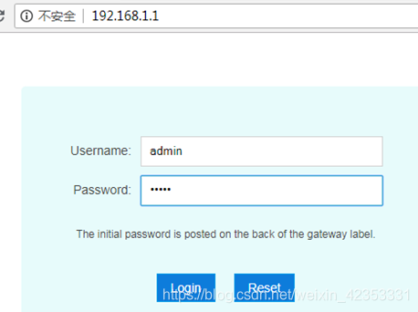
1 Web Login
Login URL:http://192.168.1.1
Supper user login account:XXX; password:XXX
Normal user login account:XXX ; password:XXX
After entering the username and password correctly, click Login button to enter the web management interface.
2 WAN Connection Create
Create multiple WAN connections (PPPOE, TR069 (DHCP), VOIP (DHCP), IPTV):
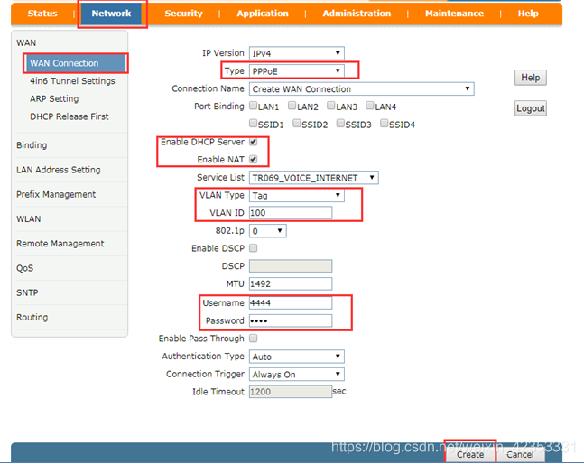
2.1 Create PPPOE WAN connection configuration
Enter the Network---->WAN—>WAN Connection interface, configure the relevant information, and click the Create button.
Type : select PPPoE
Service List :selects INTERNET or TR069_INTERNET or TR069_VOIP_INTERNET
VLAN Type: tag
VLANID: INTERNET service vlan;
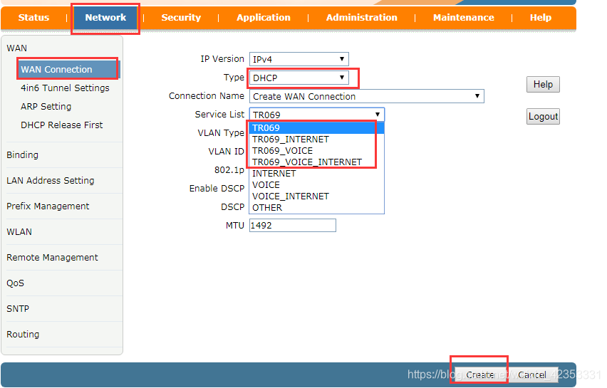
2.2 Create TR069 WAN connection
Create a tr069 (DHCP) WAN connection configuration:
Type : select DHCP
Service List : selects TR069 or TR069_INTERNET or TR069_VOIP or TR069_VOIP_INTERNET
VLAN Type:tag
VLANID: tr069 service vlan;
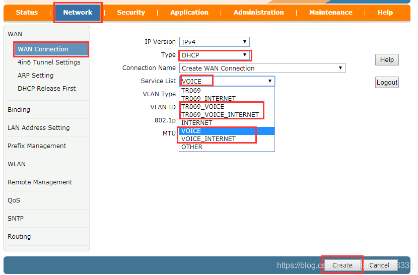
2.3 Create VOIP WAN Connection
Create a VOIP WAN connection configuration:
Type: Select DHCP
Service List: selects VOIP or VOIP_INTERNET
VLAN Type:tag
VLAN ID: Voice Service VLAN ID
2.4 Create IPTV WAN Connection
Create a IPTV WAN connection configuration:
Type: Select Bridge
Service List : selection INTERNET
Port Binding: Bind the specified LAN port
VLAN Type: tag
VLANID: Multicast vlanID

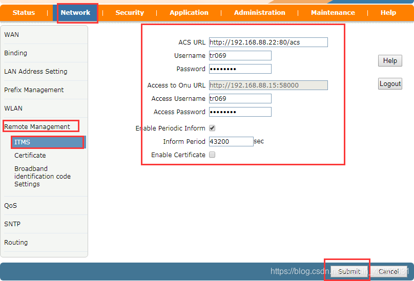
3 Remote management configuration(TR069)
Remote management configuration prerequisite: WAN connection with tr069 service must exist;
TR069 configuration: Network—>Remote Management---->ITMS interface:
Username:tr069 Password:tr069
Fill in the correct ITMS server address, username, password and other information (login and password are configured on the ITMS platform server)
Click the Submit button
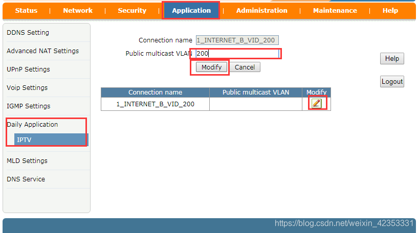
4 IPTV Configuration
Multicast configuration: Application---->Daily Application---->IPTV interface:
First find the Modify column, click the modify button for the IPTV WAN connection;
Public multicast VLAN: Set the multicast vlan;
5 VOIP Configuration
5.1 Config SIP Server
VOIP configuration: Application—>Voip Settings—>SIP page:
Sip Protocol: Select Soft Switching SIP or other
Primary Register Server: Write the correct SIP server address
Click the Submit button 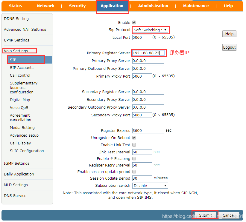
5.2 Config SIP Accounts
Application---->Voip Settings---->SIP Accounts page:
In the SIP number display column, modify the column and click the button;
Enable check;
Sip Account: Voice account;
Password: Voice Password;
Auth User name: Authentication username number;
Click the Modify button to take effect.

6 LAN interface configuration
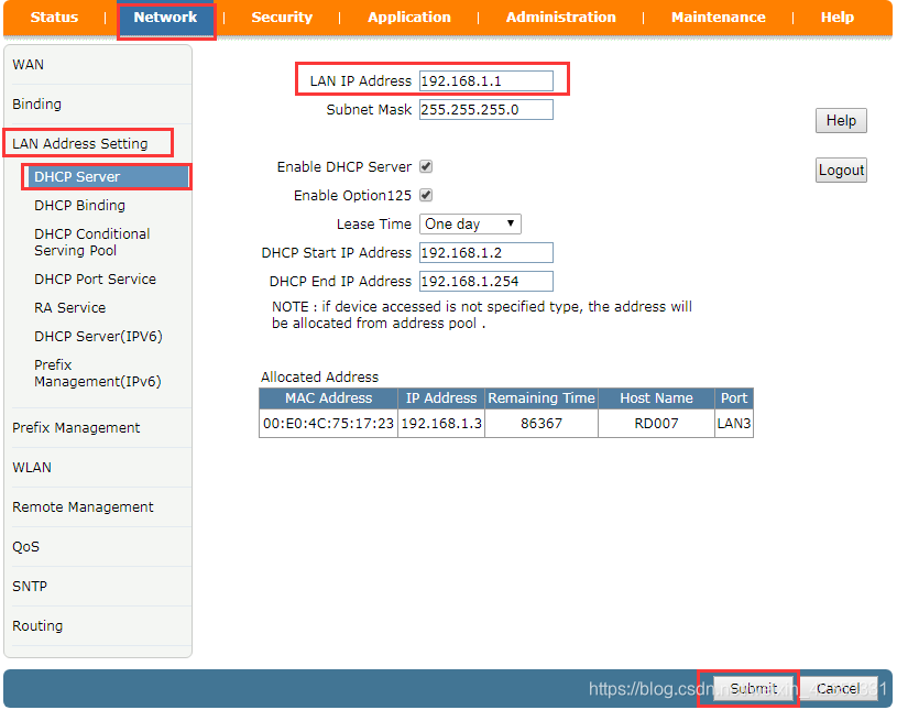
6.1 LAN IP Setting
LAN interface modification LAN_IP address configuration: Network—>LAN Address Setting—>DHCP Server interface:
LAN IP Address: LAN_IP address (can be modified)
Click the Submit button, the device will restart automatically, and it will take effect after restarting.
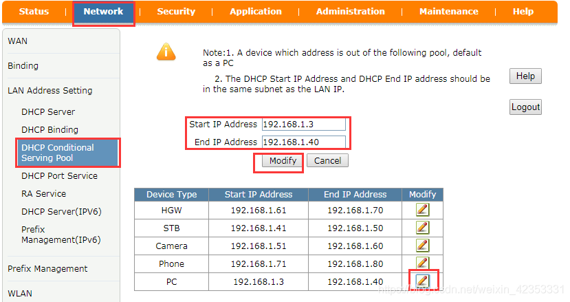
6.2 Modify LAN IP Address Pool
Modify LAN IP address pool configuration: Network—>LAN Address Setting—>DHCP Conditional Serving Pool page:
Click the Modify button after the list of IP address pools corresponding to the device properties.
Start IP Address: Start Address
End IP Address: End Address
Click the Modify button
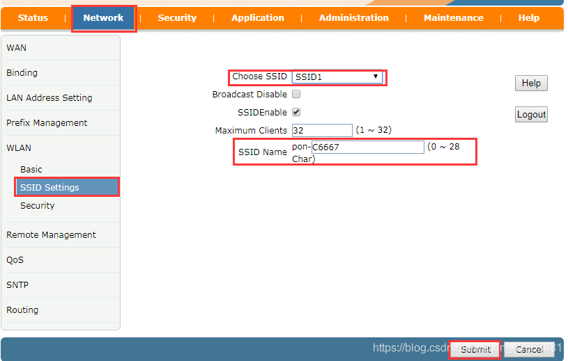
7 WIFI Configuration
7.1 WIFI SSID Configuration
Modify WIFI SSIDConfiguration:Network—>WLAN—>SSID Settings interface:
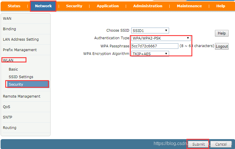
7.2 WIFI Security Configuration
Modify WIFI password and encryption mode configuration: Network—>WLAN—>Security interface.
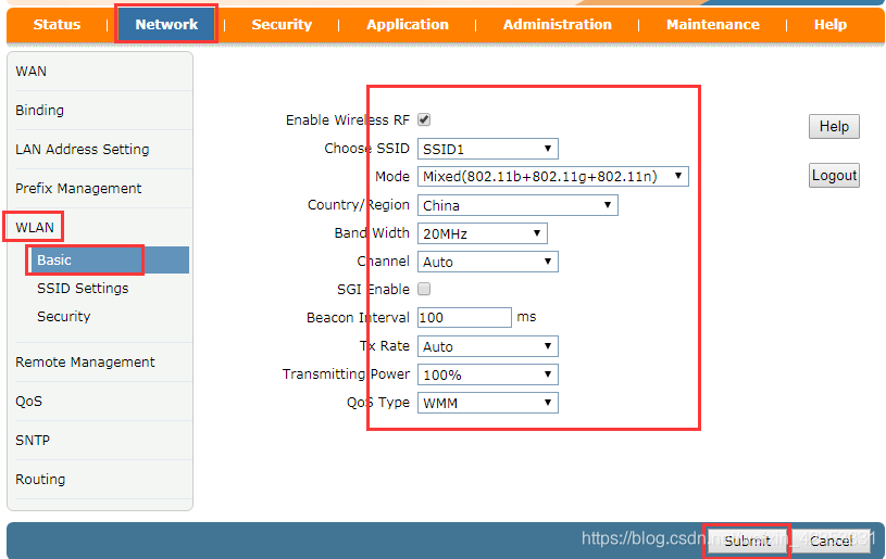
7.3 WIFI Basic Configuration
Modify the WIFI Basic page configuration: Network—>WLAN—>Basic interface
8 SoftWare Upgrade
8.1 WEB page upgrade guide
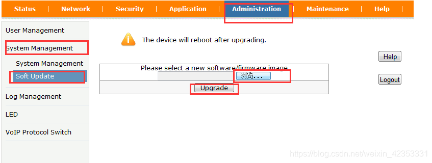
First, hide the upgrade page by logging in as an administrator user:
Website: http://192.168.1.1/getpage.gch?pid=1001&hidden=upgrade
Click Administration—>System Mansgement---->Soft Updata interface, click the “Browse” button, select the suffix name .bin upgrade file, and then click the Upgrade button. Wait 3-4 minutes, the device will restart automatically after the upgrade is completed.
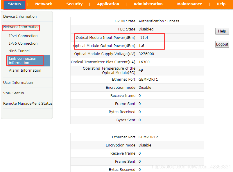
9 Optical power information inquiry
View Optical Power: Status—>Network Information—>Link connection information interface
Can view TX, RX information
10 ONU Debug
10.1 LAN SideTelnet opening Method
10.1.1 Hidden page to open telnet service
Hide telnet Open page URL: http://192.168.1.1/getpage.gch?pid=1001&hidden=telnet;
Log in through the administrator login: account: XXX password: XXXX;
Check Enable Telnet and Enable LAN Telnet to enable the LAN side Telnet service. Remove the check is disable the Telnet service.
Click the Submit button to take effect.

10.1.2The command line open the telnet service
When the telnet function is disabled, you can open the telnet service by entering the serial port.
Serial port baud rate: 115200; Account: XXX ; Password: XXXX
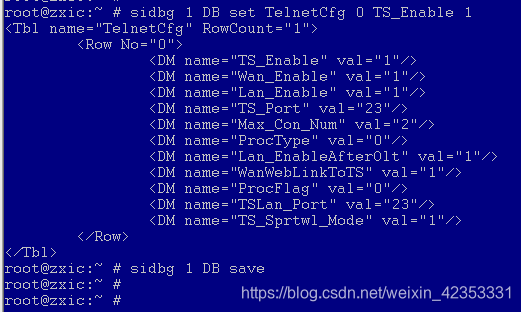
Enable the LAN side telnet function command:
Sidbg1 DB set TelnetCfg 0 TS_Enable 1 or sidbg 1 DB set TelnetCfg 0 Lan_enable 1;
Sidbg1 DB save
Restart takes effect.
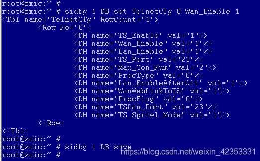
10.2 WAN Side telnet opening Method
Enable WAN side telnet function:the commandline is as follows:
sidbg 1 DB set TelnetCfg 0 Wan_enable 1;
sidbg 1 DB save
Restart takes effect.
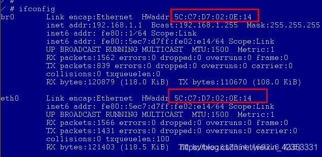
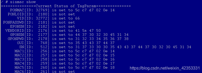
10.3 Query MAC,SN and other Informat
Telnet Enter the command line and view the MAC information by using the command: ifconfig or sismac show.
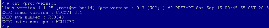
10.4 Query CPU version Information
View the CPU version information:cat /proc/version,
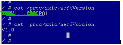
10.5 Query software and hardware version information
View the software version information:: cat /proc/zxic/softVersion
View the hardware version information:: cat /proc/zxic/hardVersion
10.6 GPON OMCI Debugg
Purpose: Grab OMCI messages
Method 1: Enter the device through telnet Command line
10.6.1 Enable serial port redirection
redir add
redir printf

10.6.2 Enable OMCI debug command
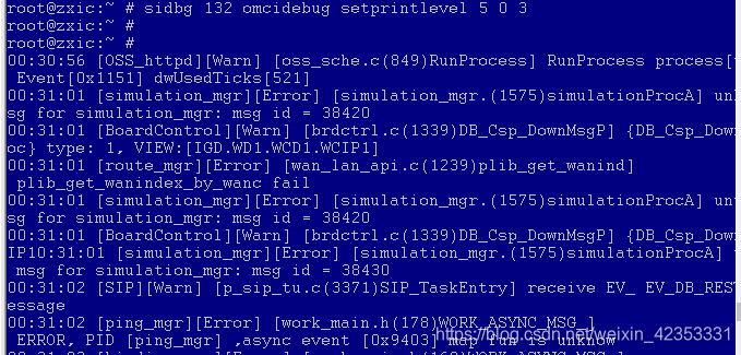
sidbg 132 omcidebug setprintlevel 5 0 3
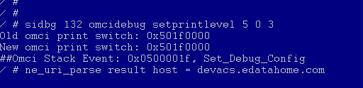
Method 2: Serial port login
Open the OMCI command:sidbg 132 omcidebug setprintlevel 5 0 3
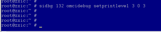
10.6.3 Disable OMCI debug commands
Disable omci debug commands:sidbg 132 omcidebug setprintlevel 3 0 3
10.7 EPON OAM Debug
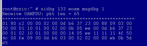
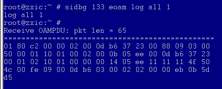
10.7.1 Enable OAM Debug
sidbg 133 eoam msgdbg 1
sidbg 133 eoam log all 1
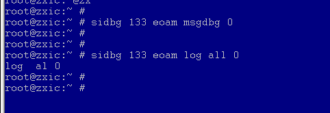
10.7.2Disable OAM Debug
sidbg 133 eoam msgdbg 0
sidbg 133 eoam log all 0
10.8 Port mirror Configuration
Purpose: Copy the data frames received or sent by the PON port to the LAN port exactly the same;
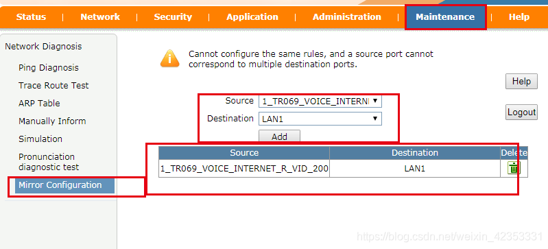
Method 1: WEB Page Add Mirror Configuration:
Enter the WEB page: Maintenance—>Mirror Configuration page:
Souce (mirror source port): Select the WAN interface to be mirrored
Destination (mirror destination port): Select the LAN port
Open the packet capture tool wireshark to grab the lan port data package.
Method 2: Enter the command line to enable mirroring: ifconfig mirror add pon0 eth0 (eth0 corresponds to LAN1 port)