Arduino例程解读与实验(1.用串口读取模拟口数据)
一、例程解读:
/*
AnalogReadSerial
//用串口通讯读取模拟口数据
Reads an analog input on pin 0, prints the result to the Serial Monitor.
//读取A0脚的模拟输入,结果显示在串口监视窗口中
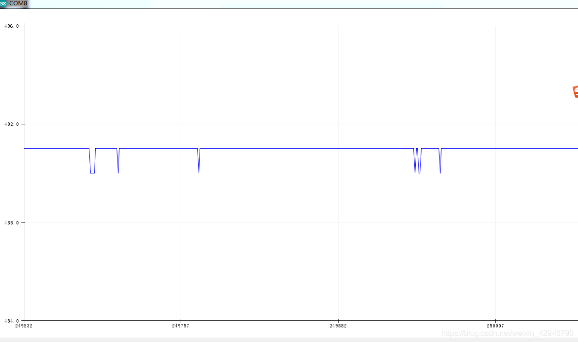
Graphical representation is available using Serial Plotter (Tools > Serial Plotter menu).
//通过设置编译器中工具>串口绘图器可以把结果以图形的形式显示在串口绘图器中。
Attach the center pin of a potentiometer to pin A0, and the outside pins to +5V and ground.//把电位器中间管脚与A0连接,两边两个管脚与电源正负极连接。
This example code is in the public domain.
例程可到下面的公共链接下载。
http://www.arduino.cc/en/Tutorial/AnalogReadSerial
*/
// the setup routine runs once when you press reset:
//按下复位键后setup()只运行一次
void setup() {
// initialize serial communication at 9600 bits per second:
//以9600 波特率初始化串口通讯
Serial.begin(9600);
}
// the loop routine runs over and over again forever:
//loop()为无限循环
void loop() {
// read the input on analog pin 0:
//读取A0脚输入值大小(0-5V对应0~1023)
int sensorValue = analogRead(A0);
// print out the value you read:
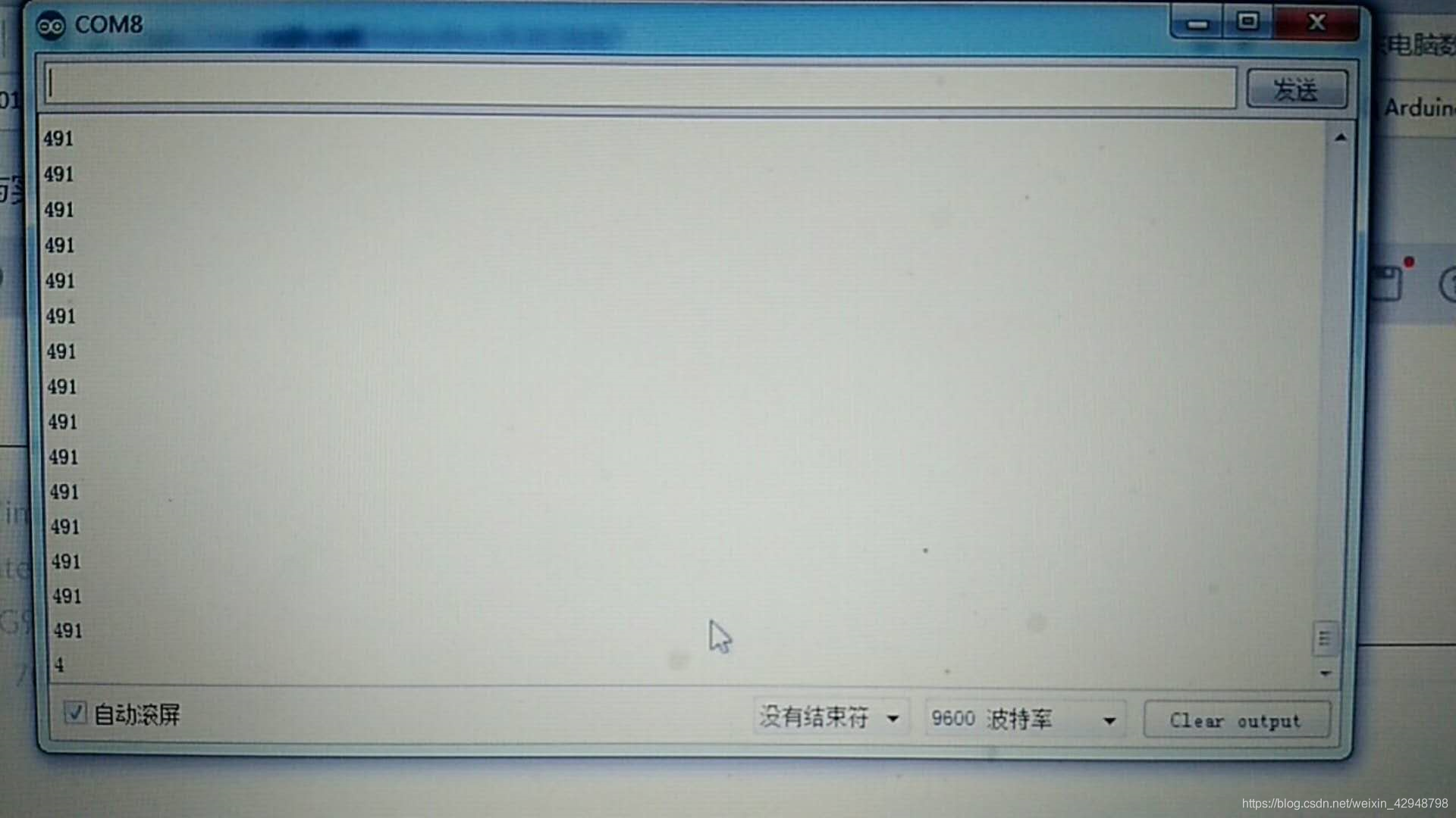
//在串口监视器上显示结果
Serial.println(sensorValue);
delay(1); // delay in between reads for stability
//在两次读数中间设置延迟1毫秒以便获得稳定的结果
}
二、实验
1.下载例程到arduino开发板
2.接线
旋钮电位器
左脚-----Arduino的5V电源
右脚------Arduino的GND
中脚-----Arduino的A0

实验结果