版权声明:本文为博主原创文章,未经博主允许不得转载。 https://blog.csdn.net/XiaoCaiDaYong/article/details/81953193
上一个博客:ESP8266 WIFI模块学习之路(1)是关于对串口连接的,简单验证ESP8266是怎么样连接及其功能验证,下面将通过单片机连接,和手机进行远程操作。
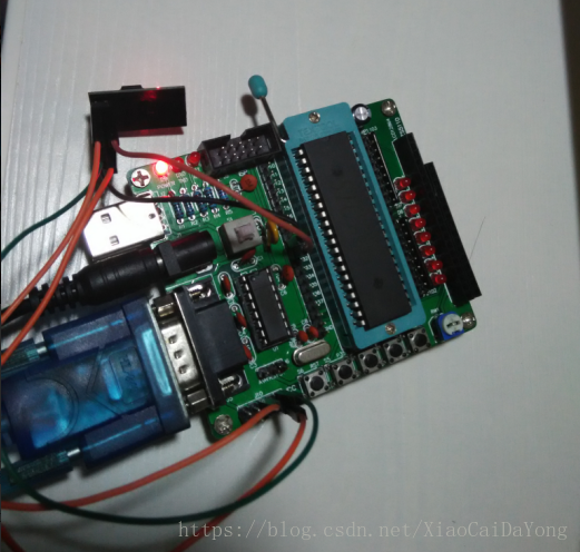
ESP8266和单片机的连接,我这里的单片机型号为:STC12C5A60S2
| ESP8266 | 单片机 |
| VCC | VCC(最好选择3.3V) |
| CH_PD | VCC(最好选择3.3V) |
| GND | GND |
| URXD | TXD |
| UTXD | RXD |
然后手机上要按照网络调试助手,这里我提供两个:
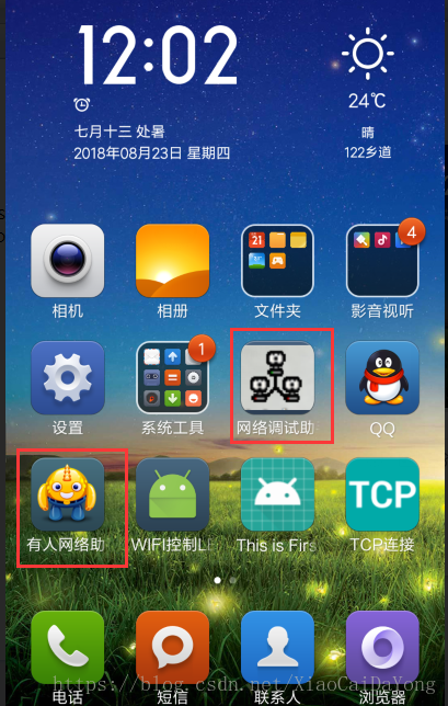
我将会上传到我的资源里,请各位需要的下载尝试。注明:我的是Android版本的。
现在我要完成的是控制P20口的LED灯亮灭,代码如下:
#include <reg52.h>
#include <string.h>
#include <stdio.h>

sbit P20_LED=P2^0;


char Recive_table[20]="";  //接收缓冲,最大20个字节
char Recive_state = 0;   //接收完成标志
void WIFI_Init(void);
void Uart_Init(void);
void ms_delay(int t);
void LED(void);

int main (void)
{
	/********************功能初始化***********************/
	Uart_Init();//串口初始化,波特率为9600
	ms_delay(1000) ;
	WIFI_Init(); //wifi初始化
	/****************************************************/
	/**********************主循环************************/
	for(;;)
	{
		ms_delay(10) ;
		if(Recive_state == 1)
		{
			ES=0;  //清空接收标志位
			if((Recive_table[0]=='+')&&(Recive_table[1]=='I')&&(Recive_table[2]=='P'))//接收到的字符串形式为+IPD,x,x:y
			{
			    if((Recive_table[3]=='D')&&(Recive_table[6]==','))
			    {
			        if(Recive_table[9]=='0')
					P20_LED = 0;
					if(Recive_table[9]=='1')
					P20_LED = 1;
				}
			}
			memset(Recive_table,'\0',20);
			Recive_state = 0;
			ES=1;  //打开接收标志位
		}
	}
	/****************************************************/

}

/******************************************************************
函 数: void Uart_Interrupt() interrupt 4
功 能: 串口中断函数,将收到的字符存到Recive_table[]数组中
参 数: 无
返回值: 无
*******************************************************************/
void Uart_Interrupt() interrupt 4
{
	static char i=0;  //因为是一位一位接收,所以用static
	if(RI==1)
	{
		ES = 0;
		RI=0;
		Recive_table[i]=SBUF;
		i++;
		if((Recive_table[i-1] == '\n'))
		{
			Recive_table[i]='\0';
			i=0;
			Recive_state = 1;
		}
		ES = 1;
	}
	else
	TI = 0;
}

/******************************************************************
函 数: void Uart_Init(void)
功 能: 串口初始化,波特率为9600(这个不会,上网百度)
参 数: 无
返回值: 无
*******************************************************************/
void Uart_Init(void)
{
	TMOD=0x20;
	TH1=0xfD;
	TL1=0xfD;
	TR1=1;
	REN=1;
	SM0=0;
	SM1=1;
	EA=1;
	ES=1;
}

/******************************************************************
函 数: void ms_delay(int t)
功 能: 毫秒级延时
参 数: 无
返回值: 无
*******************************************************************/
void ms_delay(int t)
{
	int i,j;
	for(i=t;i>0;i--)
		for(j=110;j>0;j--);
}

/******************************************************************
函 数: void LED(void)
功 能: 发送完命令后显示用的函数
参 数: 无
返回值: 无
*******************************************************************/
void LED(void)
{
	P2 = 0;
	ms_delay(100);
	P2 = 0xff;
	ms_delay(100);
}


/******************************************************************
函 数: void WIFI_Init(void)
功 能: wifi初始化
参 数: 无
返回值: 无
*******************************************************************/
void WIFI_Init(void)
{
	ES = 0;
	TI = 1;
	printf("AT+RST\r\n");
	LED();
	ms_delay(1000) ;
	printf("AT+CWMODE=3\r\n");
	LED();
	ms_delay(1000) ;
	printf("AT+CIPMUX=1\r\n");
	LED();
	ms_delay(1000) ;
	printf("AT+CIPSERVER=1,8080\r\n");
	LED();
	ms_delay(1000) ;
    printf("AT+CIOBAUD=9600\r\n");   // 设置与单片机一致的波特率
	LED();
	ms_delay(1000) ;
	while(!TI);
	TI = 0;
	ES = 1;
}
将HEX文件加载到单片机中验证效果。
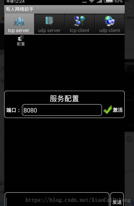
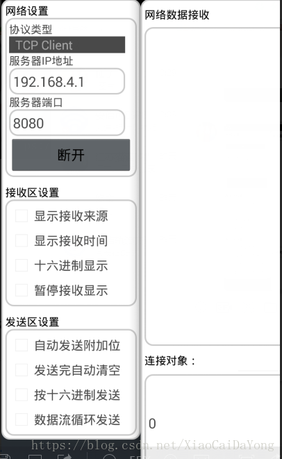
我们先用如图调试助手进行操作:

调试之前需要先连接到正确的WIFI上,我的esp8266模块的WIFI名称为:AI-THINKER_7C5C0F
TCP server端配置正确的端口号,这个端口号是自己设置的
然后在client端配置正确的IP,这个IP必须
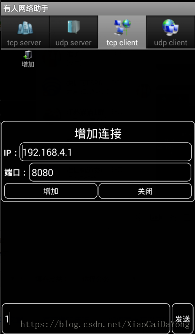
如果正确会提示连接成功,然后就可以输入0或者1进行对LED灯亮灭操作。
如图:

最后使用

同样可以完成相应的效果,配置如下图:
到此就结束了,希望大家指正,共同探讨。