本文是该系列的第11篇。从前面的设计中可以看出,System Generator最适合的是完成DSP系统的设计,可以大大提高设计效率,而其它设计任务通常仍需要使用HDL模型来设计。
但是System Generator提供了一个特性:可以通过black box这个block将其它HDL文件以黑盒的形式封装到System Generator设计中,在仿真时使用Simulink+Vivado Simulator(或ModelSim)协同仿真的方法,在Simulink环境中完成设计的仿真测试。
在本系列的第2篇中,我们用Digital FIR Filter这个block完成了数字滤波器的设计。本文设计将把其中的滤波模块改为由HDL实现,借此介绍上述功能。
本设计使用到的block
1.Xilinx block:
- Black Box(->Basic Elements):调用HDL文件
2.其它block:
- Step(Simulink->Sources):生成阶跃信号
这里给出了设计中用到的所有block在库中的路径,后文不再提及(前文用过的block没有给出;同一block会包含在多个库中,为了方便只列出一个路径)。
System Generator设计流程
本设计在第2篇设计的基础上进行修改,系统设置相同:20MHz FPGA时钟、20MHz系统采样率;对1Mhz+9Mhz的叠加信号滤波,滤除高频分量,得到1MHz频率分量。
1.完成HDL代码设计
设计的FIR低通滤波器频率响应如下图所示:
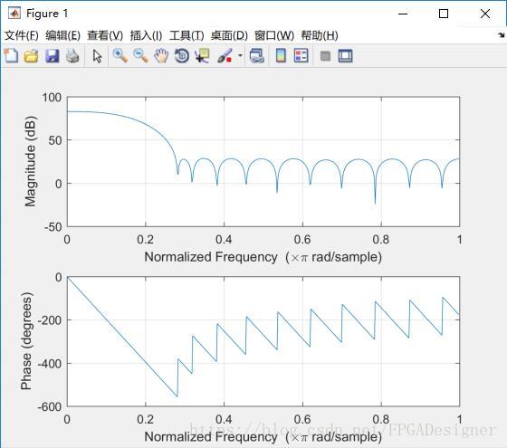
使用HDL代码实现该滤波器,具体可参考博主的《FPGA数字信号处理》系列。本设计这里使用Xilinx公司提供的一个转置型FIR滤波器设计文件,采用VHDL实现。顶层文件transpose_fir_vhd代码清单如下:
library IEEE;
use IEEE.STD_LOGIC_1164.ALL;
use IEEE.STD_LOGIC_ARITH.ALL;
use IEEE.STD_LOGIC_SIGNED.ALL;

entity transpose_fir is
    Port ( din : in std_logic_vector(11 downto 0);
           clk : in std_logic;
           ce : in std_logic;
           rst : in std_logic_vector(0 downto 0);
           dout : out std_logic_vector(25 downto 0));
end transpose_fir;

architecture Behavioral of transpose_fir is

component mac
    generic (
         coef_value : integer := 0
    );

    port(
         din : in std_logic_vector(11 downto 0);
      cin : in std_logic_vector(25 downto 0);
         clk : in std_logic;
      ce : in std_logic;
          rst : in std_logic;
      dout : out std_logic_vector(25 downto 0));
end component;

constant N : integer := 23;                     -- Number of Coefficients
type coef_array is array (0 to N-1) of integer;   -- Coefficient Values
constant coefficient : coef_array := (-38, -74, -109, -109, -37, 140, 435, 827, 1262, 1663, 1945, 2047, 1945, 1663, 1262, 827, 435, 140, -37, -109, -109, -74, -38);

signal cin_temp : std_logic_vector(26*N downto 0) := CONV_STD_LOGIC_VECTOR (0, 26*N+1);

begin

   G0: for I in 0 to N-1 generate

        G_first: if I = 0 generate

        M0: MAC
            generic map (
                coef_value => coefficient(I)
            )
            port map (
              din => din,
                 cin => "00000000000000000000000000",
              clk => clk,
               ce => ce,
                  rst => rst(0),
                 dout => cin_temp(25 downto 0));
            end generate;

    GX: if (I >= 1 and I < N-1) generate
        M1: MAC
            generic map (
                 coef_value => coefficient(I)
            )
            port map (
               din => din,
                 cin => cin_temp(I*25+(I-1) downto ((I-1)*26)),
               clk => clk,
                 ce => ce,
                  rst => rst(0),
                 dout => cin_temp((I+1)*25+I downto I*26));
            end generate;

    G_last: if I = N-1 generate
        M2: MAC
            generic map(
                 coef_value => coefficient(I)
            )
            port map (
              din => din,
                 cin => cin_temp(I*25+(I-1) downto ((I-1)*26)),
              clk => clk,
                ce => ce,
                  rst => rst(0),
                dout => dout);
            end generate;
   end generate;

end Behavioral;
其中调用的乘累加MAC单元mac.vhd的代码清单如下:
library IEEE;
use IEEE.STD_LOGIC_1164.ALL;
use IEEE.STD_LOGIC_ARITH.ALL;
use IEEE.STD_LOGIC_SIGNED.ALL;

entity mac is
   generic(
       coef_value : integer := 0
    );

    port(
         din : in std_logic_vector(11 downto 0);
      cin : in std_logic_vector(25 downto 0);
         clk : in std_logic;
      ce : in std_logic;
          rst : in std_logic;
      dout : out std_logic_vector(25 downto 0));
end mac;

architecture Behavioral of mac is

signal coef : std_logic_vector(11 downto 0);
signal product : std_logic_vector(23 downto 0);
signal addition : std_logic_vector(25 downto 0);

begin
    coef <= CONV_STD_LOGIC_VECTOR (coef_value, 12);
    process(clk, ce, din, coef)
    begin

        if clk'event and clk='1' then
            if (ce='1') then

                product <= din * coef;

            end if;
        end if;

    end process;

    -- Addition chain
    addition <= product + cin;

    -- Register result
    process(clk, ce, addition, rst)
    begin

        if (rst = '0') then

            dout <= "00000000000000000000000000";

        elsif (clk'event and clk='1') then
            if (ce='1') then

                dout <= addition;

            end if;
        end if;

    end process;

end Behavioral;
2.添加HDL代码到模型中
将两个VHDL文件放在slx文件所在路径下。添加一个Black Box到model中,会自动弹出一个窗口,选择transpose_fir.vhd文件。初始化完毕后,软件会自动生成一个transpose_fir_config.m的MATLAB配置文件,这个文件与设置的VHDL文件相对应,配置了HDL文件在Simulink环境中的具体信息。
关闭后,Black Box会根据MATLAB配置文件中的内容,自动更新block的管脚信息。有人会注意到:VHDL中定义了时钟信号clk和时钟使能信号ce,然而在Black Box上确没有显示。这是因为时钟信号clk、时钟使能信号ce会被特殊对待,在System Generator中会用设置的Simulink采样率来驱动时钟信号。具体信息可以参考本系列的第12篇。
双击打开该block:
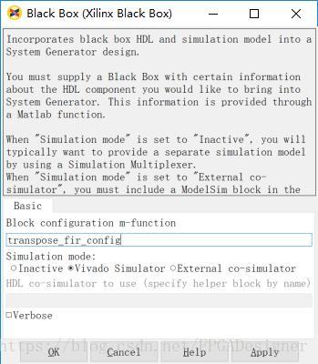
“Block configuration m-function”显示了与该block绑定的MATLAB配置文件。由于HDL文件不能直接在Simulink进行仿真,需要配置协同仿真模式,可选的Simulaion mode有三种:
- Inactive:不仿真Black Box模块,该模块的输出全为0;
- Vivado Simulator:使用Vivado自带的仿真工具进行协同仿真;
- External co-simulator:使用其它协同仿真工具(如ModelSim)。
当使用其它协同仿真工具时,还需要添加其它的block来搭建仿真源。这里为了方便,选择使用“Vivado Simulator”来仿真HDL模型。
添加一个Step到model中,设置如下:
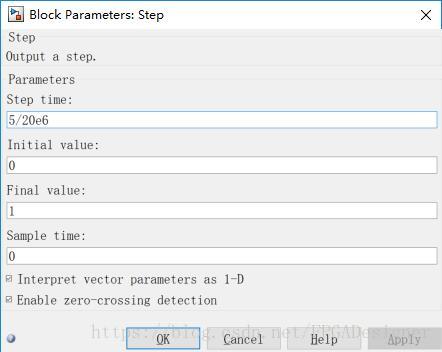
产生一个阶跃信号作为VHDL的复位信号rst。HDL代码中设计为低电平有效复位,因此这里设置“Initial value”为0,“Finial value”为1,“Step time”设置为5/20e6,即维持5个系统时钟周期的复位状态。
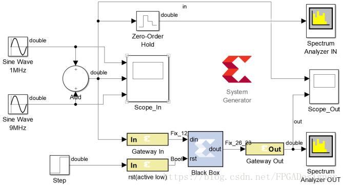
再添加一个Gateway In block,设置20Mhz采样率,复位信号为单比特,因此数据类型设置为Boolean。输入信号的Gateway In block数据格式改为Fix_12_10,与VHDL模型对应。连接系统,完整model如下:
3.修改MATLAB配置文件
系统自动生成的MATLAB配置文件只包含了软件能读取到的信息,其它信息还需我们自己设置。本设计需要修改以下两点:
- VHDL设计中采用的是带符号定点数,因此将第26行的 “dout_port.setType(‘UFix_26_0’);”改为“dout_port.setType(‘Fix_26_23’);”,否则在Simulink环境中用示波器无法正确显示block的输出。
- 该block只关联了transpose_fir.vhd文件,而该文件还调用了子模块mac.vhd文件。在第64行将注释改为“this_block.addFile(‘mac.vhd’);”,添加该文件,否则仿真时不能正确运行。
4.运行仿真
运行仿真,仿真时间设置为“2000/20e6”,滤波前后频谱图对比如下:
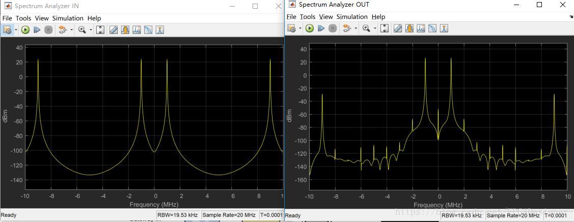
可以看到经过滤波后,9MHz频率分量的信号有明显衰减。示波器波形如下:
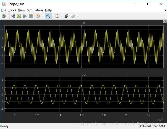
明显看到1MHz+9Mhz的叠加信号经过滤波后只剩下1Mhz的正弦波。
本文以Black Box导入HDL文件的形式重新设计了第2篇中的数字滤波器,并使用Simulink+Vivado Simulator进行了协同仿真。关于Black Box的具体特性即MATLAB配置文件的更多内容可以参考ug958文档,或本系列的第12篇。