The motion system positions the probe relative to the product in 4 degrees of freedom. The product is mounted on an air bearing spindle (), and the probe is positioned over it in radial (r), vertical (z) and inclination (ψ) direction by the R-stage, Z-stage and Ψ-axis, respectively. The motion system should provide a sub-m repeatable plane of motion to the probe. The Z-stage is hereto aligned to a vertical plane of the granite base using three air bearings, to obtain a parallel bearing stage configuration. To minimize distortions and hysteresis, the stages have separate position and preload frames. Direct drive motors and high resolution optical scales and encoders are used for positioning. Mechanical brakes are applied while measuring a track.
Measurements have been performed on the noise level, eigenfrequencies and stage tilt. Frequency responses have been measured to design robust motion controllers.
3.1 Concept
3.1.1 Requirements
The motion system positions the probe relative to the product by moving the probe in r, z and ψ-direction, and rotating the product in -direction. The required stroke is 400 mm, 150 mm and 165° in r, z and ψ-direction, respectively (see section 2.2). It should provide a high-accuracy plane of motion to the probe, preferably with sub-m repeatability in the out-of-plane directions (y, ϕ and θ). In principle, repeatable
behaviour in r and z-direction is not required due to the separate metrology system. The interferometers measure the probe position at the Ψ-axis centre, so the probe length causes an Abbe error for ψ-rotation. Besides the out-of-plane directions, the ψrotation of the probe should thus also be highly repeatable.
The machine will mostly be operated in circular measurement mode, during which the probe is positioned on a circular track and all stages are clamped using mechanical brakes. The stages thus move step-wise in this mode. In some cases, however, the probe may also be scanned over the surface, with or without a rotating product. This would give a spiral and radial scan respectively. A radial scan is for instance applied for drift compensation in section 7.2.3. For convex and concave surfaces, these scans require smooth and continuous motion of all stages. For this scanning mode, friction should thus be minimized for repeatability in the r and z-direction.
Since the measurement spot of the probe is only a few micrometers, high resolution scans on a small area may deliver valuable information on the surface mid-spatial frequencies. High-resolution positioning capabilities are hereto desired of the stages.
3.1.2 Basic components and principles used
Several basic components and principles are applied throughout the machine and are therefore explained first. These mainly concern the air bearings and their preloading, the actuators, the optical scales and encoders and the brakes.
Air bearings and cardanic hinges
The Z-stage is to be directly aligned to a vertical base plane, resulting in 2 DOF (r,z) relative motion. Air bearings are particularly suitable for this. They provide high stiffness and long range of motion. Due to the buffer effect they also have relatively high damping. The absence of Coulomb friction allows for infinite positioning resolution. The accuracy of the guiding surfaces can be (sub-)micrometer level. Gap height stability is only as good as its air supply, so care must be taken to avoid pressure variations, for instance by applying a pressure vessel. Gap height stability can be in the order of nanometers this way, with good straightness of motion and repeatability. Clean, dry air generally is available in metrology laboratories and workshops. Considering the above, air bearings are very suitable for application in this instrument.
Several air bearing types have been developed in the past, such as parallel gap, conical gap, and infinite stiffness membrane compensated bearings (Holster, 1967; Vermeulen, J., 1999; Vermeulen, M., 1999; Van Beek, 2006). Porous graphite air bearings are increasingly applied for their high load capacity, robustness to dry running and their commercial availability. Figure 3.1 (left) shows a photograph of a porous graphite air bearing.
Bearings of ∅150 mm, ∅125 mm and ∅100 mm are applied in the machine. Load capacity and stiffness were tested before installing the bearings in the machine. The load was applied by varying the pressure inside an air piston, while measuring the gap height using three LVDT gauges around the bearing (Figure 3.1, right).

Figure 3.2 shows the test results as well as the load characteristic from the supplier, both at 5.5 bar supply pressure. The bearings do achieve their specified load capacity, but at a smaller air gap than specified. For robustness to dust and scratches, the bearings are chosen to operate at a minimum gap height of 10 m. This provides a stiffness of about 2.8⋅108 N/m at 2000 N preload for the ∅150 mm bearings, 2⋅108 N/m at 1500 N preload for the ∅125 mm bearings and 1.4⋅108 N/m at 1000 N preload for the ∅100 mm bearings.

Figure 3.2: Air bearing test results at 5.5 bar
To enable the bearings to adjust themselves parallel to the guiding surfaces, elastic cardanic hinges are applied (Figure 3.3), similar to (Vermeulen, J., 1999 and Vermeulen, M., 1999). These provide 2 rotational degrees of freedom with intersecting axes of rotation, high axial stiffness and no friction and hysteresis.
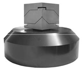
Figure 3.3: Cardanic hinge for bearing self-alignment
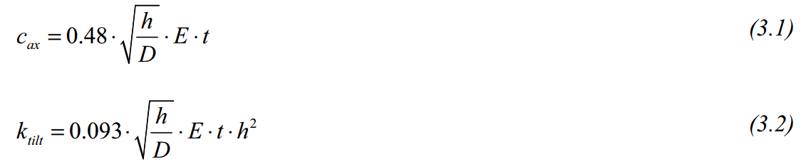
The cardanic elements are manufactured from 34CrNiMo6 steel with a yield strength of 900 N/mm2. The hinges have a hinge thickness h of 0.5 mm, width t of 2x30 mm and diameter D of 3 mm, giving a rotational stiffness of 114 Nm/rad (3.1) and an axial stiffness of 2.4⋅109 N/m (3.2). FEM calculations show an axial stiffness of 5.3⋅108 N/m for the middle body including the stiffening strips, giving a total axial stiffness of 3.7⋅108 N/m for the cardanic element.
Bearing and cardanic hinge assemblies as shown in Figure 3.3 are used throughout the machine for the position determining bearings. The combined stiffness of these elements is 1.6⋅108 N/m for ∅150 mm, 1.3⋅108 N/m for ∅125 mm and 1⋅108 N/m for the ∅100 mm bearings. These values will be used for calculating the rigid body modes of the stages in this chapter.
Force closed preload
The preload forces are 2000 N, 1500 N and 1000 N for the ∅150 mm, ∅125 mm and ∅100 mm bearings, respectively. This force can be applied by mass, vacuum or an opposing bearing. In some cases, the attraction force of an iron core linear motor is utilized for the preload (Slocum et al., 2003). Preloading by mass may lead to pneumatic hammering (Holster, 1967; Vermeulen, M., 1999) and deteriorates dynamic behaviour. At 5.5 bar supply pressure, preloading by vacuum requires at least 5.5 times more vacuum area as bearing area, and is vulnerable to fluctuations in vacuum pressure. Preloading with an opposing bearing is therefore preferred. Force closed preloading with an air piston is applied, which is less sensitive to guidance parallelism and temperature fluctuations compared to form closed preloading. This therefore has better repeatability.
Figure 3.4 shows a preload piston as applied for all preload bearings in the machine. It consists of a cup and a disc, separated by an O-ring. The diameter has been chosen such that the desired preload force is obtained at 5.5 bar, such that all bearings and pistons operate on the same supply pressure.
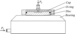
Figure 3.4: Air bearing with preload piston
The opposing bearing can generally be applied in three configurations, as shown in Figure 3.5. A strip-on-edge C-yoke can be applied around the guiding surface (Figure 3.5A). Each bearing thus has an individual yoke, and the preload bearings become individual mass-spring systems attached to the main stage structure. Especially when motion in two directions is intended, the yoke must leave space for this, requiring a relatively long horizontal part (1).
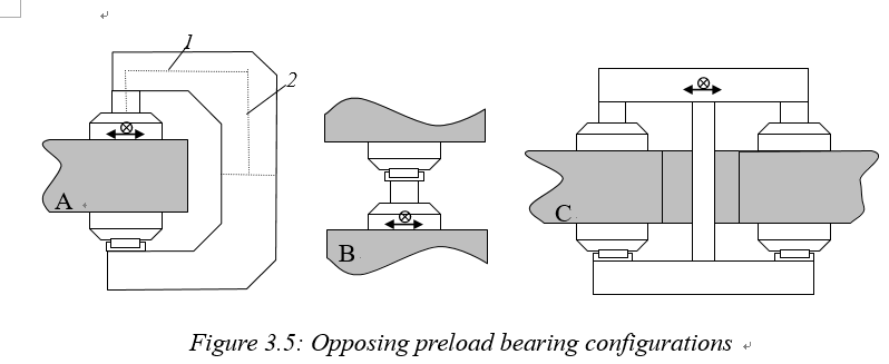
The total deflection δ for a C-yoke consists of deflection of the horizontal part (δ1) and the rotation ϕ2at the end of the vertical part times the length of the horizontal part (l1), and can be approximated by (3.3). This means that when I1 ≈ I2 and l1 ≈ l2, 75% of the deflection is caused by bending of the vertical part.

Applying two bearings between two guiding surfaces (Figure 3.5B), does not require the yoke, but the base structure is now loaded with bending and tension instead of compression.
By pairing 2 or 3 bearings, pure tension is obtained in the centre pull rod and symmetrical bending in the connecting beams (Figure 3.5C), similar to (Van Seggelen, 2007). The deflection is now a function of the 3rd power of the length of the horizontal beam. More height is generally available here to create more bending stiffness. Since the bearings are spaced some distance apart to obtain tilting stiffness, the space in between can be used for the pull rod. This avoids large c-yokes extending from the machine to enable 2D motion. For 2D motion, this paired setup is therefore preferred.
Separate position and preload frames
The large preload forces required for high-stiffness air bearings also give rise to large stresses and deformation in the stage structure. To minimize hysteresis due to varying preload forces, for instance when turning the supply pressure on and off, the function of position and preload frame can be separated. Figure 3.6 shows this for the paired bearing setup. The c-yoke configuration of Figure 3.5A is also a separate preload frame.
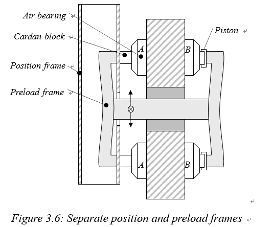
These frames take the preload force, to minimize stress in the position frames. Hysteresis will thus occur in the preload frame, but with the critical components attached to the position frame this will hardly affect the measurement uncertainty.
Principally, the preload frame only has to take the force required to preload the position determining bearings (A) and can thus be designed for strength rather than stiffness. The preload frame and preload bearings (B) are, however, also part of the dynamic behaviour of the stage, and resonances in this frame do influence the position accuracy of the critical components on the position frame. The preload frame thus has to achieve similarly high eigenfrequencies in order not to interfere with the position frame. This basically means that two full stage structures have to be integrated into one.
Direct drive brushless motors
For actuating the linear and rotary stages, brushless direct drive motors are applied. These motors are frameless and can thus directly be mounted to the stages. Since there are no brushes and bearings, there is no wear, friction or play, allowing for high resolution positioning and high bandwidth.
For the stages, Tecnotion UL series ironless linear motors (www21) have been selected (Figure 3.7, left). This motor has the highest motor constant (km) that fits within the available design volume, to minimize heat generation. The motors consist of a U-shaped steel magnet carrier and an epoxy coil carrier. The absence of iron in the windings eliminates attraction forces and cogging, but also reduces the efficiency compared to iron core motors. The U-shaped magnet setup limits the amount of leak flux. Commutation of the three motor phases is done electronically by the amplifier. This specific motor type has no Hall sensors for commutation. The magnet orientation is detected at amplifier power up by an automated ‘wake-and-shake’ procedure, after which a linear scale signal is required for high resolution commutation interpolation.
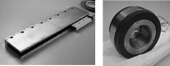
Figure 3.7: Linear ironless motor (www21) and DC brushless motor (www2)
For the Ψ-axis and spindle, rotating frameless brushless direct drive motors are applied (Figure 3.7, right). These motors have the same advantages as the linear motors. This specific motor has Hall sensors so commutation is detected instantly at amplifier power up. The commutation is interpolated by the amplifiers using the available encoder.
Optical linear scales and encoders
For the R- and Z-stages, interferometers are already available to measure the stage position. These are incremental, so they do not provide an absolute ‘home’ position.
This signal may easily be interrupted if the beam is accidentally blocked. Further, the interferometry system is one of the last modules to be assembled to the machine. To have a robust position feedback for the stages and motor commutation, high resolution optical scales and encoders are added. Heidenhain LIP481R scales have been selected (Figure 3.8, left), which have a 4 m line pitch, outputting a 1 VPP/2 m. This allows for 5 nm resolution after 400-fold interpolation. One reference mark is present in the middle of the range.
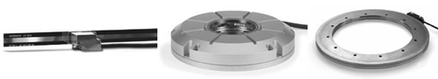
Figure 3.8: Linear scale and angular encoders (www8)
For the spindle, the highest accuracy angular encoder with a central hole available, the Heidenhain ERP880 (Figure 3.8, middle), was selected. This encoder operates with the interferential scanning principle and has 90.000 lines (180.000 signal periods) and one reference mark, giving 0.17 rad resolution after 200-fold interpolation. The data acquisition electronics can sample up to 500 kHz, allowing for 2.7 rev/s.
The Ψ-axis requires a large central hole. An Heidenhain ERA4280 ring encoder is applied here (Figure 3.8, right). This encoder has 20.000 lines and has distance coded reference marks. The angular resolution is 1.6 rad resolution after 200-fold interpolation.
Brakes
The stages will be mechanically clamped after positioning the probe on a circular track. Better stability is obtained compared to servo-controlling the stages, especially for high frequency disturbances which are more difficult to measure and compensate for. This is partially because the mechanical clamp can have higher stiffness than the controller, and partially because scale, encoder and amplifier noise are not fed back into the motors. On the other hand, dominant frequencies may be notched by a controller, which is not possible with a mechanical brake.
The design[1] of the R and Z-stage and spindle brake is more or less similar, consisting of a monolithic elastic clamp which is normally closed by a preloaded spring and opened by an air piston (Figure 3.9). Two cylindrical Tungsten Carbide contacts clamp a strip that is attached to the stages. The two hinges (hinge 1) allow the clamp to adjust to sideways misalignment of the brake strip, while the hinges behind the contact points (hinge 2) allow the line contact to adjust to the orientation of the brake strip.
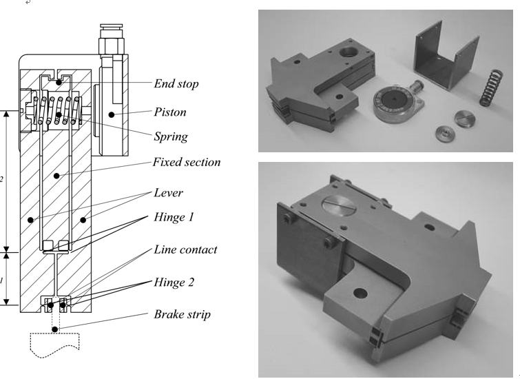
Figure 3.9: Brake design and realization
The brake stiffness and hysteresis calculations and test results are shown in Appendix C. The calculated stiffness of the brake is 2.4⋅108 N/m. Tests however showed a much lower stiffness, mainly due to limited stiffness of the supposedly ‘rigid’ world. Since this is difficult to improve, the measured stiffness of 5⋅107 N/m (Aerts, 2007) will be used for further calculations in the coming sections.
3.1.3 Motion system concept
The concept was shown schematically in Figure 2.6. The product is placed on a spindle since it is more or less rotationally symmetric. Together with the long range optical probe, this allows for high scanning speeds with minimal system dynamics. Since the products may weigh up to 50 kg, a vertical spindle setup provides the best accessibility for mounting and aligning products. An axially loaded spindle further provides the best error motion properties. A vertical spindle, however, also requires the r, z and ψ motion to take place in a vertical plane, which requires extra measures to overcome gravity. The advantages for the operator are considered more important.
A plane of motion is to be provided to the probe with sub-micrometer uncertainty. Initially, it was considered to align the probe directly to a vertical plane using a single air bearing, since this allows for 3 degrees of freedom: the r and z-translation and the ψ-rotation. This was found not to be practical due to the large required range of motion in ψ-direction (-45° to +90°). Next best is to perform the ψ-rotation with a separate bearing stacked on top of the Z-stage, such that the Z-stage only has to perform the r and z-translations. The Z-stage can be aligned to a vertical base plane using three air-bearings. This is expected to improve the stiffness (especially in direction) and guidance accuracy compared to a stacked pinole stage design. The vertical moving mass however also increases. The following section briefly describes the evolution of the stage design.
Z-stage bearing layout
From a dynamics point of view, the Z-stage main tube should be directly above the probe and Ψ-axis, to have the probe reaction forces in the same plane as the bearings that guide the sides of the Z-tube. The probe and Ψ-axis are, however, moving underneath the horizontal beam of the metrology frame. The main tube of the Z-stage is therefore positioned directly behind this beam. This means that reaction forces of the probe servo system cause a moment around the length direction of the tube. This is an extra argument to align the Z-stage with 3 bearings to a vertical plane since this provides better rotational stiffness. The vertical base plane is positioned directly behind the edge of the mounting table, at 320 mm from the spindle centre line. The main tube of the Z-stage is aligned with two bearings at the bottom and one at the top. In section 3.1.2 it was shown that force closed preloading with opposing bearings is preferred. These preload bearings of the vertical stage can basically be configured in three ways: with individual c-yokes, with a common c-yoke and with a central pull rod through a gap in the base plate.
Figure 3.10 shows the preload configuration with three c-yokes (1), dimensioned for the required range of motion. This requires the lower two ∅100 mm bearings (2) to be spaced 1040 mm apart to allow for 400 mm range of motion in r-direction for the top bearing. This is relatively far, requiring a high bending stiffness of the bridge (3) between the lower bearings. Further, the yokes must provide sufficient z-range which results in large deflections and low stiffness for constraining the in-plane degrees of freedom of the preload bearings (4).

Figure 3.10: Z-stage preload with c-yokes
Figure 3.11 shows a preload configuration using one large central preload bearing (1). This bearing can be better constrained, for instance by using a tubular preload frame with large cross-section (2). Using a ∅150 mm bearing at the top and two ∅100 mm bearings at the bottom, results in the centre of force at half height between the bearings. A single ∅200 mm bearing provides enough load capacity to preload the three front bearings. The lower bearings can now be spaced closer together (~350 mm), which still provides plenty of rotation stiffness in -direction. The separate tubular preload frame (2) can be inside the Z-tube and built around the base in a big C-yoke to close the force loop. The required preload force is 4000 N, which results in millimeter order deflection in the tubular frame. Further, a bending moment is introduced in the vertical base plate (3) which decreases the flatness of the plane of motion.
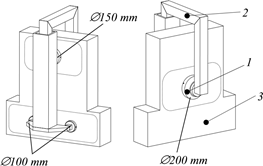
Figure 3.11: Z-stage preload using one central bearing
Using a central gap (1 in Figure 3.12) in the base with a pull tube (2) allows for a stiffer preload body that connects all the bearings. Since the forces are balanced, only tension is present in the pull tube which significantly reduces the total deflection. By using three preload bearings (3), the bending moment on the base is also removed. The attainable eigenfrequency for this preload frame is probably also higher than for the tubular C-frame of Figure 3.11.

Figure 3.12: Z-stage preload with paired bearings through a central gap
The required range of motion in r is relatively large compared to z: 400 and 150 mm, respectively. The properties of Figure 3.10 are limited by the bending stiffness of the bridge. For smaller, squarer ranges of motion the configuration with the three C-yokes of Figure 3.10 may result in less moving mass and higher eigenfrequencies compared to Figure 3.11 and Figure 3.12.
Two main concepts have evolved, one in which a single preload bearing is applied (based on Figure 3.11) and one in which a central gap is applied (based on Figure 3.12). This choice has consequences for the R-stage design and preload, the base shape and the metrology frame connection.
Concept 1
The first concept (Figure 3.13 and Figure 3.14) has a single preload bearing for the Zstage, as shown in Figure 3.11, and is adapted from the concept developed in (Henselmans, 2003). In this concept, the base is built from two flat plates (1 and 2) that make the vertical and horizontal guidance plane. The horizontal plate contains a hole in which the spindle (3) is mounted via a flange.
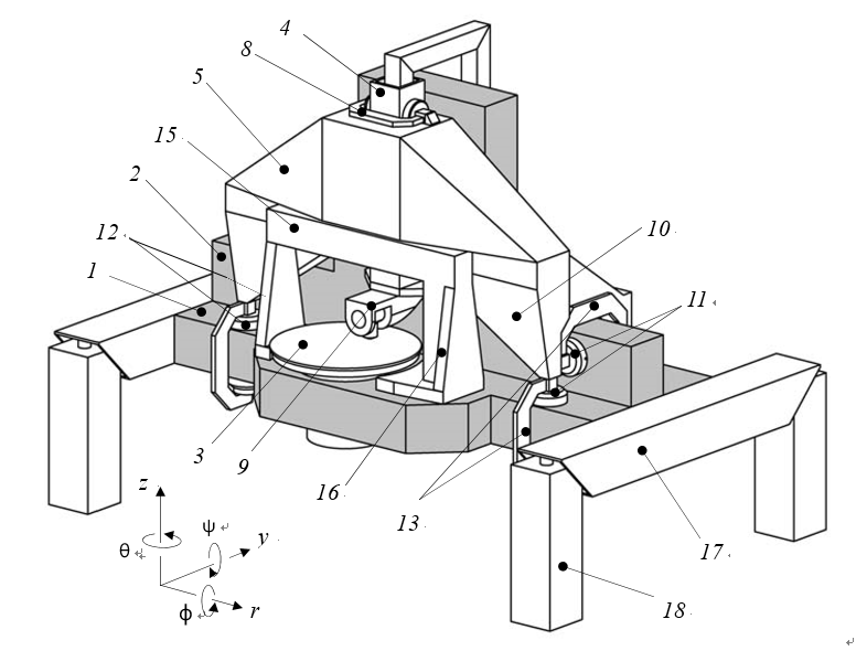
Figure 3.13: Machine concept 1, based on Z-stage with one central preload bearing
The r and ψ-direction of the Z-stage (4) are constrained relative to the R-stage (5) by two fixed (6 in Figure 3.14) and two preload bearings (7 in Figure 3.14) on the sides of the Z-stage main tube. Separate yokes (8 in Figure 3.13) keep the preload forces separated from the R-stage position frame. The dimensions of the probe and Ψ-axis (9) determine the minimal vertical position of the Z-stage, to maintain enough clearance from the measurement volume. The top position of the Z-stage determines the position of the bearings (6 and 7) that guide its tube and with that the vertical dimension of the R-stage is set. These bearings are to be supported towards the horizontal guidance plane. The box structure of the R-stage hereto has two legs (10) extending towards two pairs of horizontal and vertical bearings (11 and 12) that are preloaded by c-yokes (13).

Figure 3.14: Machine concept 1, front and back view
With the y, z, ψ and -direction of the R-stage constrained, only the ϕ-direction remains. This can be constrained with a 3rd bearing high on the vertical plane, or with a 3rd bearing on the horizontal plane at the backside of the base. Since vertical stiffness is more important, the last option is chosen here (14).
The volume of the metrology frame (15) is also shown. Since the R-stage moves behind this frame, a direct support towards the vertical base plane to provide out-ofplane stiffness can not be made. Two flanges (16) are therefore added.
To support the base, two beams (17) are bolted to the sides of the horizontal base plate. These beams extend to the front and backside of the machine to the vibration isolators (18).
Some concerns remain with this concept. Since the probe and Ψ-axis require the Zstage to be positioned quite high above the product, the R-stage is also high. This causes its centre of gravity to be far away from the bearings, in horizontal as well as vertical direction. The front c-yokes and preload bearings prevent the base frame beams from being closer together, which causes the large rectangular footprint of the machine of 2.6 x 1.7 m. The centre of gravity of the machine is also high above the isolators, which may cause tilting stability issues in the ϕ-direction. All c-yokes form individual mass-spring systems, giving a large number of eigenmodes at a relatively low frequency. The bearing configuration in this concept prevents out-of-plane stiffness to be provided from the vertical base plane to the metrology frame. Consequently, the metrology frame mounting stiffness is limited.
Concept 2
The second machine concept (Figure 3.15 and Figure 3.16) is based on the central gap in the vertical base plate of Figure 3.12 for preloading the Z-stage (1). The base now consists of three pieces (2, 3 and 4). The spindle (5) is mounted in a hole in the bottom block, again via a flange.
The Z-stage is guided relative to the R-stage (6), again by two fixed (7) and two preload bearings (8), shown in Figure 3.16. The dimensions of the Ψ-axis and probe (9) have not changed, so the position of the Z-stage relative to the product has also remained the same as in concept 1.
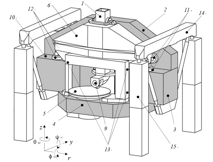
Figure 3.15: Machine concept 2, based on Z-stage with paired bearings through a central gap in the base
The horizontal guidance plane (10) has been raised to the same level as the gap in the vertical plane. This also raises the horizontal and vertical bearing pairs (11 and 12) of the R-stage, and thus lowers the centre of gravity of the R-stage relative to its bearings. Raising the horizontal guidance plane level further creates support points
(13) for the metrology frame in out-of-plane direction. It also requires the vertical guidance plane to consist of two pieces (2 and 3), which reduces the achievable flatness (see section 3.2.1). The preloading of the R and Z-stage is further explained with Figure 3.17.
To support the base block, it is mounted onto two triangular frames (14). With the two struts intersecting below the centre of gravity of the machine, almost pure tension and compression is present in the beams. With the isolators (15) raised towards the end points of the triangles, the centre of gravity of the machine is now below the mounting points. This assures tilting stability when the mass of the stages moves from side to side, and reduces the footprint compared to concept 1 to a more square 2.1 x 1.85 m. It may however also amplify lateral vibrations of the floor if the isolators are not sufficiently compliant in lateral direction.
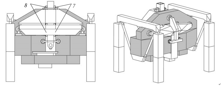
Figure 3.16: Machine concept 2, front and back view
Figure 3.17 shows a close up of the backside of the machine with a section of the base cut out, and the R-stage preload frame coloured gray for clarity. Just as the first concept, the R-stage has two horizontal (1) and two vertical (2) bearings at the front. The R-stage extends backwards through the gap in the base. To constrain this stage in ϕ-direction, one central horizontal bearing at the backside would be sufficient. The pull tube (3) of the Z-stage preload frame, however, drops to the level of the horizontal plane (4), to keep the overall dimensions minimal. This leaves no space for a single bearing. Two horizontal bearings (5) are therefore positioned left and right of the preload tube. To avoid over-constraining the R-stage, the stage structure has been given a torsional degree of freedom.
Preloading the two horizontal bearings (1) at the front of the R-stage with c-yokes would require very high yokes now. Preloading the vertical bearings with yokes around the vertical base plate has also become difficult because base material is required left and right of the central gap. An R-stage preload frame (gray) has therefore been designed that also makes use of the same central gap. A horizontal beam (6) is connected at the front side of the R-stage position frame (at 7), directly above the two bearing pairs. A tube (8) extends backwards from this beam. From this tube, two arms (9, left one blanked) extend to the two vertical preload bearings (10). This forms an H-shape in the horizontal plane that connects the vertical position determining and preload bearings. Because there is plenty of room to create a large box structure, the deflection of this large frame can be kept below a few tenths of a millimeter.

Figure 3.17: Concept 2 cross-section showing preload frame structure
To preload the four horizontal bearings (2 and 5), two plates (11 and 12) extend downwards from the central preload frame tube (8). The bottom base block (13) is connected to the middle block (14) such that it leaves a slit (15), through which the front plate (11) extends. Between the front and back plate, a box (16) is attached that carries two horizontal preload bearings (17). Together with the stage mass, these bearings provide the required preload force in the centre of force between the four horizontal bearings. The large height of the middle base block should provide enough bending stiffness against the bending moment that is introduced this way. To constrain the parallelogram motion of this part of the preload frame, a small extra support bearing has been added, as will be further explained in section 3.5.2.
Comparison
The vertically moving mass is approximately similar in both concepts. The mass of the R-stage will probably also not be very different, be it that most of the mass is concentrated in the position frame in concept 1, and spread over position and preload frame in concept 2. The total moving mass is thus very similar. All bearings have similar dimensions, so the static stiffness is also similar. The fourth horizontal bearing gives concept 2 slightly higher vertical stiffness. Since most moving mass is high above the R-stage bearings in concept 1, the dynamic behaviour and eigenfrequencies are expected to be better for concept 2. Furthermore concept 2 has a lower centre of gravity relative to the isolator mounting points, and therefore has better tilting stability when the stages are moving in the r-direction. The bearing preload frame of concept 2 allows for three mounting points from the base to the metrology frame in the out-of-plane direction. Concept 1 has bending in the vertical base plate, directly influencing the flatness of the plane of motion, but this will be repeatable. Concept 2 has no bending in the vertical plane, giving a better plane of motion. It does have some bending in the stiff horizontal base plate, causing (repeatable) tilting of the Rstage in ψ-direction. The footprint of concept 1 is 2.6 x 1.7, where the footprint of concept two is smaller and squarer with 2.1 x 1.85 m.
Considering the above, concept 2 is chosen. This comes at the cost of a more intricate and complex design, but the identified improvements in performance justify the added level of complexity.
3.1.4 Dynamic analysis
To estimate the dynamic behaviour of concept 1, a multi-body dynamic analysis was done. Hereto a model was made using Matlab SimMechanics (Figure 3.18), with which spindle unbalance, floor vibrations, excitation of the probe objective and moving of the stages were simulated. The resulting relative motion between probe tip and spindle is calculated this way. Some of this motion is compensated for by the metrology system, giving an estimate of the remaining measurement error due to machine dynamics. Although the final stage mass and stiffness of concept 1 and 2 are somewhat different from this model, it can still be used for an estimate of the errors to be expected from machine rigid body dynamics.
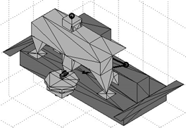
Figure 3.18: Multi-body dynamical simulation model of concept 1
From these simulations, it was concluded that spindle unbalance for typical eccentricities (smaller than 0.1 mm) does not result in significant relative motion, and thus also negligible measurement errors. Floor vibrations may result in several tens of nanometers of relative motion, but most of this is corrected for by the metrology system. No significant errors are thus expected from floor vibrations.
In the above model, a single sided Ψ-axis bearing was applied, as further discussed in section 3.6.1. Probe objective motion caused quite large tilts of the Ψ-axis rotor, and thus a considerable second order errors for this setup. A symmetric bearing should therefore be applied for the Ψ-axis.
Estimates of the dynamic behaviour will be made throughout the next sections with the mass and stiffness of the actual design. Where possible, the flexible body behaviour of the stages will also be taken into account.
3.1.5 Design overview
The following sections treat the design details of the main sub-systems of the motion system (Figure 3.19). The base will be explained first in section 3.2, followed by the spindle in section 3.3. Next, the Z-stage (section 3.4) and R-stage (section 3.5) will be shown, and the Ψ-axis will be explained last in section 3.6. The motion system assembly and experimental results will be discussed in section 3.7 and 3.8. The motion control will be discussed in section 3.9.
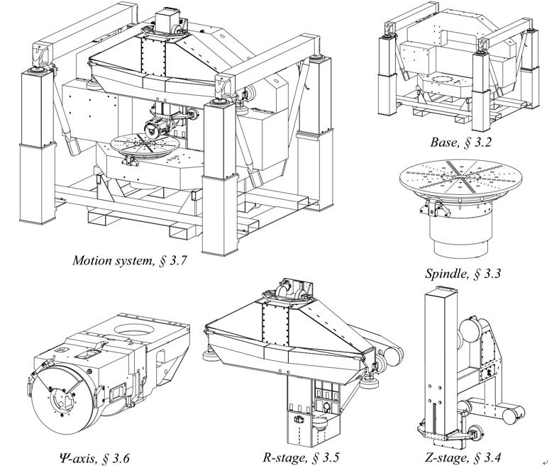
Figure 3.19: Motion system main sub-systems
3.2 Base
The base assembly consists of a granite block assembly, to which the spindle and metrology frame are mounted and that provides the guidance surfaces for the air bearings of the R- and Z-stage. This block is suspended on vibration isolators via two triangular frames. Transportation of the machine is possible by a forklift frame underneath the base block.
3.2.1 Base block
The granite base block (Figure 3.20) is built from three pieces: the bottom (1), middle (2) and top (3) block. It was designed in close collaboration with manufacturer Botech BV (www6). The bearing surfaces are shown dotted.
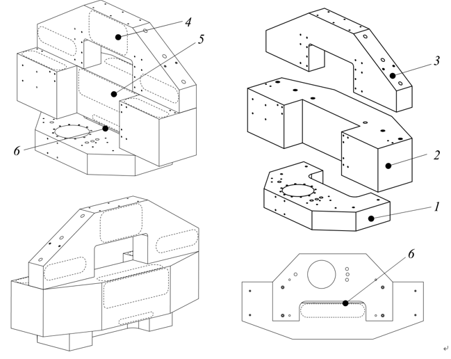
Figure 3.20: Base block assembly
The top and bottom block are bolted to inserts in the middle block using M20 bolts. After alignment was approved, capillary adhesive was applied around the seams to permanently fix the blocks. The bearing surfaces visible in the front view are all for fixed bearings, the surfaces visible in the back and bottom view are preload surfaces. The surfaces for the fixed bearings were ground and lapped flat to within 2 m and the preload faces to 5 m. The bearing surfaces for the Z-stage (4 and 5) were measured to be parallel within 1 m. Steel inserts are applied for attaching various components. The slit for the R-stage preload frame is also shown (6).
The total mass of the assembly is 2150 kg and the first resonance is a bending mode at 336 Hz (Figure 3.21). The second resonance is a torsional mode at 342 Hz. The base block assembly is modelled as a single body, and the mass of the spindle and mounting table (215 kg) has been taken into account in this calculation.

Figure 3.21: Base block eigenmodes
The maximum deflection due to gravity is approximately 4.6 m at the front of the bottom base block (Figure 3.22, left). The maximum deflection of the horizontal guiding surfaces of the R-stage is 1.5 m, giving 1.8 rad of tilt per side. During lapping, the middle block is supported on its final mounting points so most of this deflection is lapped out during manufacturing. The added mass of the bottom and top block still cause some deflection.
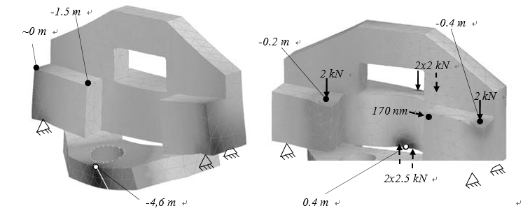
Figure 3.22: Base deformation from gravity (left) and R-stage bearing preload (right)
The R-stage bearing layout causes a 3 point bending moment on the base. When the stages move from left to right, the load also shifts, causing the R- and Z-stage to tilt in mainly the ψ-direction. The deflection for 2 kN on the fixed bearings and 2.5 kN on the preload bearings is shown in Figure 3.22, right. The difference between the left and right bearing is 0.2 m over 1.4 m bearing spacing, or a tilt of 0.14 rad in ψdirection. This is well within the requirements for the interferometry system alignment, and probably even also highly repeatable. Having a central preload bearing is thus not a problem in this case, due to the large height of the middle block.
A plate will constrain the upper metrology frame in r-direction relative to the base (see section 4.3.4). The mounting point of this plate shifts about 170 nm when the Rstage moves from left to right. This shift will be eliminated from the metrology loop by a compensation mechanism.
Figure 3.23 shows the base block under construction at Botech BV, and the completed block just after delivery to the TU/e GTD workshop.
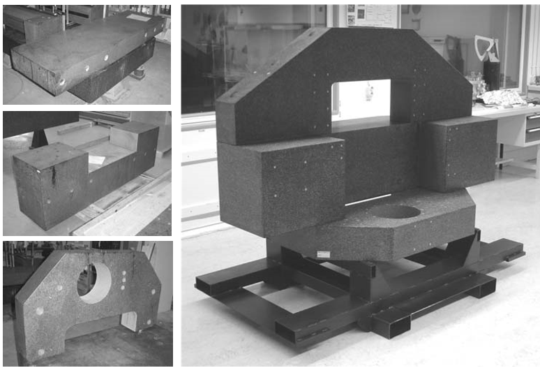
Figure 3.23: Base block
3.2.2 Vibration isolation
The base block is suspended onto four Newport I-2000S passive vibration isolators (1 in Figure 3.24). These isolators consist of a vertical air-spring with damping via a porous restriction, and horizontal isolation via an oil-damped pendulum. Mechanical levelling valves increase or decrease the pressure inside the air volume to adapt to shifting of the load due to moving of the stages. Each isolator is rated up to 900 kg, so with a total suspended mass of around 3000 kg, four are required. This also gives more tilting stability compared to three. The block is hanging in two triangular frames (2), with two plates (3) attaching the block to the top beams of these frames to constrain the sideways swinging degree of freedom. A rubber layer (4) is applied in this connection to provide damping between the steel beams and the block. This prevents acoustic vibrations in the low-damped steel triangles to propagate into the base block.
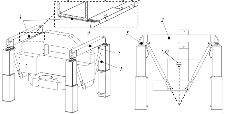
Figure 3.24: Base vibration isolation
The two struts cross below the centre of gravity of the machine (CG), resulting in almost pure tension and compression in the beams. This setup results in a centre of gravity that is about 450 mm below the mounting points (5), which gives inherent tilting stability and lowers the tilting frequency of the base. It also allows for an almost square footprint that is no wider than the base block itself. The final footprint size is 2.1 m x 1.85 m.
Isolation quality
When the machine is simplified to a dual mass-spring system (Figure 3.25), the isolation quality is given by (3.4), similar to (Vermeulen, M., 1999), and is equal to the ratio between the amplitude δ at the probe tip and the floor amplitude zg. The Newport I-2000S isolators have a mass independent resonance frequency fisol of around 1 Hz in vertical and 1.5 Hz in horizontal direction. The first (measured) eigenfrequency feq at the probe tip is about 75 Hz in vertical and 50 Hz in horizontal direction (see section 3.8.2).
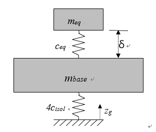
Figure 3.25: Base dual mass model and tilt model
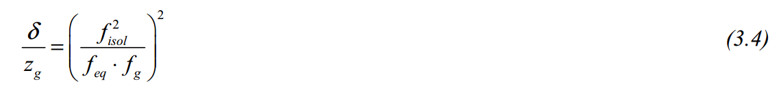
Metrology laboratories typically have independent foundations providing floor frequencies fg of around 5 Hz (Figure 3.30), which gives an isolation quality of 7⋅10-6 in vertical and 8⋅10-5 in horizontal direction. Translated to floor amplitude this gives a typical zg of 3 m, resulting in a displacement δ at the probe tip of 0.02 and 0.25 nm in vertical and horizontal direction, respectively. These values are only an indication of the actual displacements. In practice, these values will be higher due to parasitic stiffness of cables and non-ideal behaviour of the isolators. To calculate the remaining vibration amplitude spectrum at the probe tip more accurately, one may also use the Power Spectral Density of the actual laboratory in combination with the isolator and machine frequency response.
Levelling
When the stages move from left to right, the base will tilt in ψ-direction (Figure 3.26).

Figure 3.26: Machine levelling model
In case of a tilt, the equation of moments consists of a moment of the static mass (stat), the moved mass (mov) and the isolator springs (isol):
M stat + Misol − Mmov = 0
M stat = mstat ⋅ g ⋅sin(ψbase )⋅hCG
Misol = kψ⋅ψbase (3.5)
Mmov = mmov ⋅ g ⋅ΔR
Using the small angle approximation, the base tilt can herewith be expressed as:

The total moving mass mmov (stages, probe and interferometry system) is approximately 275 kg and the stationary mass mstat (base, spindle and metrology frame) is approximately 2600 kg. This brings the total mass mtot to 2875 kg that is suspended at 1 Hz. Using (3.7), this gives a vertical isolator stiffness of 2.8⋅104 N/m.

The isolators are spaced 1860 mm apart, resulting in a tilting stiffness kψ of the base of 1⋅105 Nm/rad (3.8).

When the R-stage moves from the centre position to the outer right position, it displaces 200 mm. The centre of gravity of the stationary mass is approximately 450 mm below the mounting points on the isolators. When no active levelling is applied, this results in a base tilt of 4.8 mrad. This is equivalent to 4.5 mm displacement at the isolators. Since there is no friction and a direct drive motor is applied, the R-stage motor would have to counter this tilt with about 13 N.
The afore-mentioned only happens when the R-stage moves swiftly (tens of mm/s) from left to right. The valves of the levelling system respond to approximately 0.1 mm displacement at the valve. The tuning of the levelling system restriction is a compromise between settling time and levelling speed. Since the primary mode of operation will be circular scanning, low settling time (high damping) is preferred above levelling speed. In practice, base tilt is negligible when scanning circular tracks, as is thus also the case for the required R-stage motor force.
3.2.3 Transportation
A forklift frame is present under the base block (Figure 3.27, gray). When the isolators are pressurized, the base is lifted 5 mm above this frame. Four bolts in inserts in the bottom of the base, extend into oversized holes in the forklift frame. The isolator columns are also attached to this frame. The bolts limit the range of motion of the base relative to the isolators to prevent the whole assembly from falling over.

Figure 3.27: Transportation frame
When the isolators are depressurized, the block lands on the frame. After removing the triangular frames and the isolator columns, a footprint of 2.1 x 1.25 m remains. This is narrow enough to fit through a double door. In the top view (Figure 3.27, right), the transportation frame (gray) extends from under the machine in all directions, which protects the sensitive parts of the machine for instance from hitting a doorpost during transport.
During development of the machine, the TU/e GTD workshop moved to a new building which forced the transportability of the machine to be tested in practice (Figure 3.28). To prevent air bearing damage due to vibrations, air supply was maintained using a pack of compressed air cylinders. Small jacks were used to lift the machine and mount rollers underneath. It was then pushed towards to loading dock and into a truck by hand. At the new location, a forklift then lifted the machine out of the truck and onto the loading dock, after which it was rolled towards its new position.

Figure 3.28: Machine transportation during GTD move
3.2.4 Base assembly
Figure 3.29 shows the base assembly. Due to late delivery of the isolators, the spindle is already installed in this photograph. Warnings are placed on the bearing surfaces, to prevent damaging the surfaces. The total mass of the assembly is 2850 kg (spindle not included), of which 2350 kg is suspended on the vibration isolators. The footprint is 2.1 x 1.85 m, and the height is about 1.7 m.
Figure 3.29: Base assembly
3.2.5 Vibration measurement
To measure the quality of the vibration isolation system, measurements were taken with an acceleration sensor (B&K 8318C). The vertical vibration levels were measured on the base and on the floor. Since only one sensor was available, no frequency response could be derived. It should further be noted that the measured vibration levels on the base are around the minimum specified sensitivity of 10-5 m/s2 of this sensor. The achieved reduction can still clearly be seen in Figure 3.30. Around 2-3 Hertz, the vibration level on the base is slightly higher than on the floor. This is due to the amplification around the isolator resonance frequency. A sharp 50 Hz peak can also be seen from EMC interference of the mains. The source of the other peaks in the base measurement has not been investigated.

Figure 3.30: Measured vertical vibration levels on floor and base
The above measurements were taken at the former TU/e GTD workshop. The final machine validation measurements are performed at the new location at the TNO Eindhoven facility. No accelerometer measurements were performed here. The actual influence of the remaining vibration between probe tip and spindle is measured in section 3.8.2. The measured vibrations originate from floor vibrations, acoustic excitation and internal sources. The measured vibration levels are sufficiently low, so it can be concluded that the vibration isolation performs as required.
3.3 Spindle
The spindle assembly consists of an air bearing spindle that is mounted to the base via a flange. A steel mounting table is bolted to its rotor, on which the reference edge for the error motion measurement is machined. Some first ideas for a universal intermediate body are explained. A brake disc and calliper allow for locking the spindle when measuring a radial track or when mounting a product.
3.3.1 Air bearing spindle
After a survey of commercially available large air bearing spindles, the Professional Instruments BlockHead 10R spindle was selected (Figure 3.31). This spindle has the best stiffness, load capacity and error motion specifications compared to other vendors products at the time. The spindle bearing, mounting flange, motor and encoder were delivered as a complete assembly by the manufacturer.

Figure 3.31: BlockHead 10R air bearings spindle (www3)
The bearing consists of a double thrust bearing on the top and bottom with a central radial bearing in between. This makes it very suitable for a vertical setup with heavy products. At 8 bar supply pressure, the axial stiffness (cS,ax), radial stiffness (cS,rad) and tilt stiffness (kS,tilt) amount to 1.4⋅109 N/m, 2.8⋅108 N/m and 9⋅106 Nm/rad, respectively. The axial working load capacity is 430 kg. The axial and radial error motion is specified as smaller than 25 nm and the tilt error motion as smaller than 0.1 rad. The total mass of the bearing is 68 kg, of which 32 kg is the rotor with an inertia of 0.254 kgm2. The normalized air consumption is about 85 l/min.

Figure 3.32: Air bearings spindle cross-section and in test setup
The spindle assembly shown in Figure 3.32 consists of a ring shaped stator (1) and a rotor (2) built from two thrust bearing discs (3) connected by a tube that functions as a radial bearing (4). A flange (5) was added to mount the bearing into a hole in the base
(6). The base and flange faces were manufactured to high flatness tolerances, allowing them to be bolted together face to face with minimal distortion of the spindle. To measure the rotation angle of the spindle, a Heidenhain ERP880 optical encoder (7) was installed. At the time, this was the best encoder available with a central hole. This central hole was to remain open for calibration purposes, as will be further discussed in sections 4.3.5 and 7.3. The encoder has 90.000 lines, resulting in 180.000 signal periods of 1 Vpp per revolution. According to Heidenhain, 200-fold interpolation may be reliably applied, resulting in 0.17 rad resolution, or 44 nm in tangential direction at the outer edge of the measurement volume. The encoder has one reference mark, and system accuracy is specified at 1 arcsec, or 4.8 rad.
To drive the spindle, an MCS B20-13 brushless DC motor (8) was installed by the manufacturer. This motor has a high motor constant of 0.65 Nm/√W, to limit the heat produced during operation. At startup, Hall sensors provide the rotor orientation for commutation. To assure smooth commutation, the amplifier uses the encoder signal to interpolate between the Hall sensors. Regular amplifiers can not cope with the high line count of the ERP880 encoder. A second encoder, a Renishaw RESR ring encoder with 20.000 lines (9), was therefore installed to aid commutation. The total inertia of the rotor assembly is 0.3 kgm2. The assembly was obtained from the spindle manufacturer to prevent distortions from affecting the bearings air gaps.
3.3.2 Product mounting table and intermediate body
Stress-free mounting of optics is a science in itself and not included in the scope of this thesis. The stiffness required during machining is generally much higher than the stiffness required during operation. Statically determined mounting, for instance using three hinged leaf-springs generally is not sufficient (Van Venrooy and Ploeg, 2005). Another complication is that machining and measurement is usually done in vertical and/or horizontal setup, while the product may have any orientation relative to gravity in the final application. In space applications, gravity is not even present.
In polishing, it is common to attach the optic to a counter formed intermediate body using pitch or wax. By pushing the product into the molten wax, it is attached stressfree and with even support stiffness over its entire surface. In diamond turning, surfaces with a flat backside are generally clamped onto a vacuum chuck. Provided that the backside and the chuck are (diamond turned) flat, this provides relatively low mounting stresses and high stiffness. In some cases, for instance in open back structures, this is not possible and bolting the product to the chuck is necessary. Much care must be taken not to deform the product in this case.
Ideally, a universal intermediate body is applied in single-piece production, to which the product is waxed or bolted. This body serves as a quick and repeatable interface between manufacturing and measuring machine. Some first ideas are explained in Appendix D.
Mounting table
The mounting table is a solid steel disc, 600 mm in diameter and 40 mm thick. A solid disc provides highest stiffness within the available dimensions, and mass is no issue since the higher inertia only aids in keeping a constant speed. Steel was chosen to match the thermal expansion coefficient of the spindle, and to provide a hard, damage resistant mounting face. The total mass is 75 kg and the inertia is 2.9 kgm2. The table has twelve rows of M5 holes for bolting or clamping a product or intermediate body to the table (Figure 3.33).
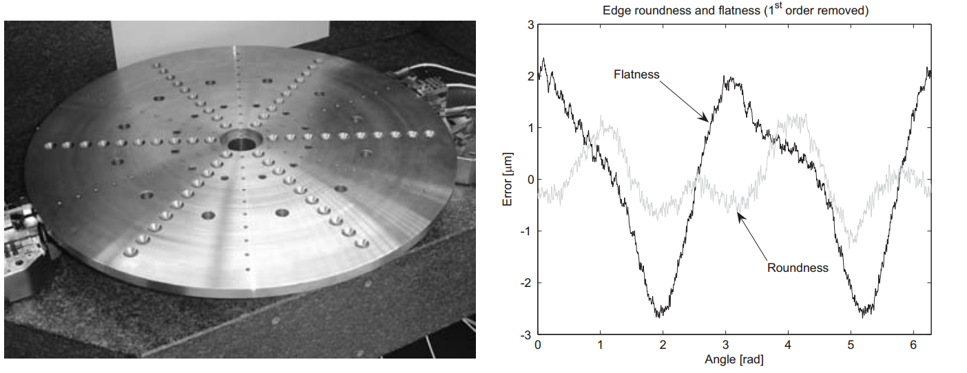
Figure 3.33: Mounting table and edge profile
As will be explained in section 4.4, the error motion of the spindle is measured by capacitive probes measuring to the edge of the table. This reference edge is machined onto the side and bottom of this table using a conventional 1960s carousel lathe. The steel disc was taken from a rod of bulk material instead of plate to have an axial symmetric stress distribution that allows for better flatness. After warming up the machine overnight, the edge was machined to a PV roundness of 2.3 m and a PV flatness of 5.1 m (Figure 3.33, right). The table was Nickel plated to protect it from corrosion. The profiles shown are actual capacitive probe signals with their first order (eccentricity and tilt) removed. Axially, the profile is mainly a 2nd order profile, indicating warp. Radially, the profile is less clear, but some elliptical form can be distinguished.
3.3.3 Spindle brake
When performing a radial scan or when installing a product, the spindle is clamped. A ring (1 in Figure 3.34) has hereto been lasercut from a stainless steel plate. This ring is bolted to the bottom of the table via 12 spacers (2). The brake clamp (3) is similar to the clamp mechanism described in section 3.1.2, but has a 90° bend in it. This way it can be bolted to inserts on the front of the bottom base block (4) via a spacer (5).
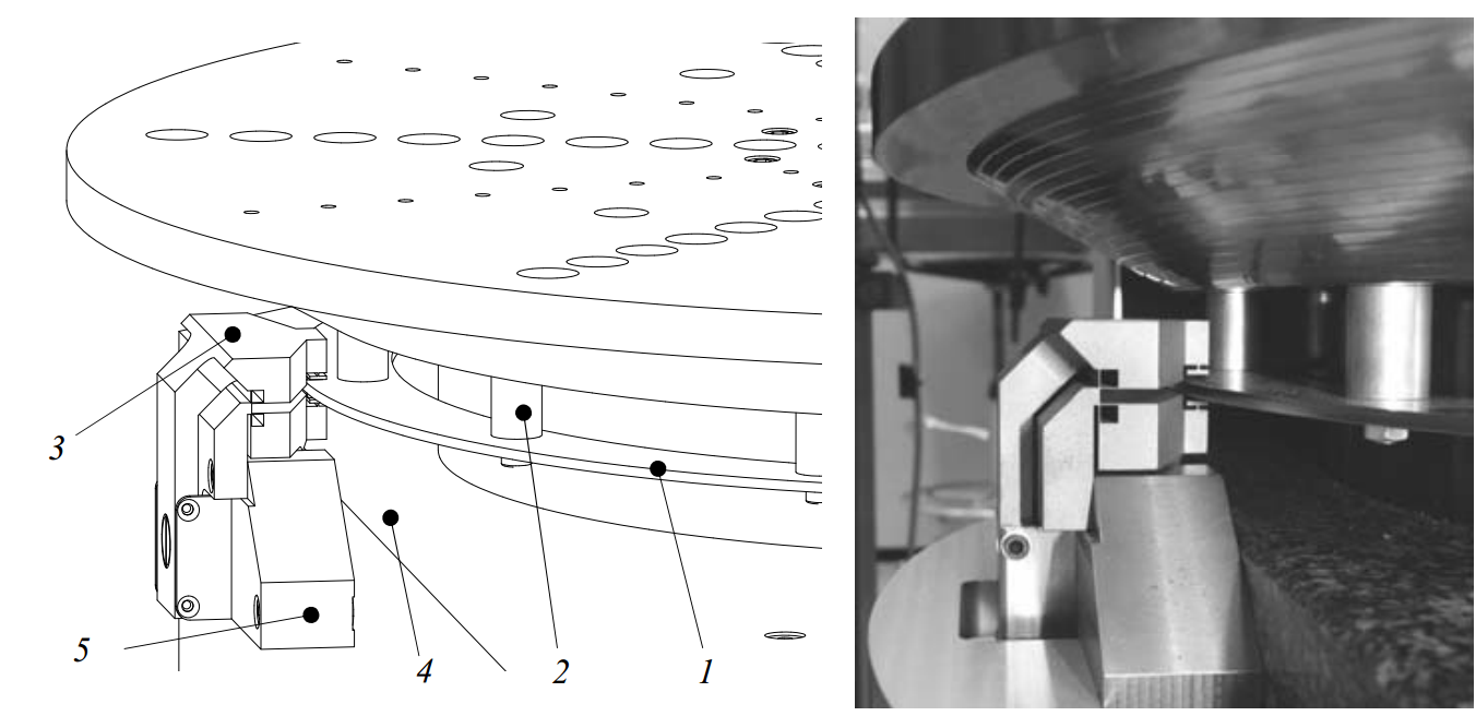
Figure 3.34: Spindle brake
As explained in section 3.1.2, the brake clamp has a stiffness of 5⋅107 N/m between the contact points and the base. The contact is at a radius of 230 mm, giving a rotation stiffness of 2.6 ⋅106 Nm/rad. The total inertia of the rotor, motor, encoders and table is 3.3 kgm2, giving a resonance around the centre line of 141 Hz.
3.3.4 Spindle assembly
The spindle assembly with mounting table and brake is shown in Figure 3.35. The lower metrology system is already installed around the spindle in this photograph.
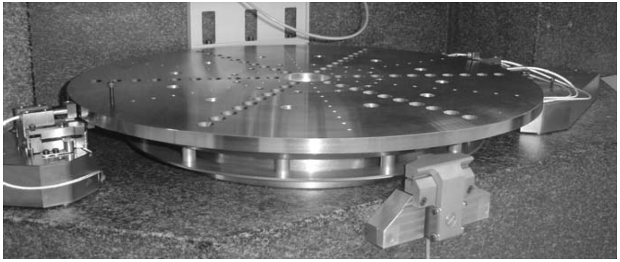
Figure 3.35: Realized spindle assembly
The total mass of the spindle assembly is about 215 kg. The rotor, motor, encoder and mounting table mass is 120 kg. Table 3.1 summarizes the theoretical spindle properties. Experimental validation will be done in section 3.8.2.
| i |
cS,i [N/m] |
mS,i [kg] |
fS,i [Hz] |
|
i |
kS,i [Nm/rad] |
JS,i [kgm2] |
fS,i [Hz] |
| z |
1.4⋅109 |
120 |
544 |
ϕ, ψ |
9⋅106 |
2.4 |
308 |
|
| r, y |
2.8⋅108 |
243 |
θ (brake) |
2.6⋅106 |
3.3 |
141 |
Table 3.1: Spindle assembly theoretical rigid body properties
3.3.5 Error motion measurement
Several experiments were conducted to check the spindle after delivery. First of all, the air gap, stiffness and load capacity were verified. Using three LVDT probes, one central and two on the edge of the rotor, an air gap of only 3.5 m was measured. This is relatively small for an air bearing and probably explains the high stiffness of this particular bearing.
After installing the spindle into the base, and bolting on the product mounting table, the error motion was measured to verify that no distortion was introduced during mounting, and to provide comparable results for testing the multi-probe method (section 4.4.2). The roundness of a steel reference sphere was first calibrated at NMi VSL. The minimum zone roundness profile is shown in Figure 3.36 (left). A contact stylus with a tip radius of 1.8 mm was used for this measurement. Capacitive probes with a spot diameter of 2.5 mm will be used in the experiment, which have different filtering properties. The roundness profile is hereto filtered by a flat averaging filter with 2.5 mm width, to approximate this effect.

Figure 3.36: Reference sphere roundness (by NMi) and spindle error motion setup
The reference sphere was centred on the spindle, and an axial and radial capacitive probe were attached to the Ψ-axis rotor (Figure 3.36, right). The probes were aligned with the centre of the sphere by moving the stages towards the maximum readout of the capacitive probes. The Z-stage was landed for optimal stability. Tests were performed at 0.1, 0.5 and 1 rev/s with a sample rate of 1 kHz. At each speed, 20 revolutions were recorded.
Figure 3.37 (left) shows the axial measurement, which is by definition equal to the synchronous axial error motion (ASME, 1985). It can be seen that the synchronous axial error motion is 9 nm PV with a clear first order component.

Figure 3.37: Axial synchronous error motion and radial capacitive probe signal
In Figure 3.37 (right) the radial measurement is shown. The reference sphere profile is also shown, from which a large radial error motion could be concluded. A multistep measurement (ASME, 1985; Whitehouse, 1976; Grejda, 2002), however, indicates the contrary, as will be explained in the next paragraph.
The deviation from the average at 1 rev/s is shown for 20 revolutions in Figure 3.38, with a mean rms of 2.9 nm and 3.2 nm respectively. The noise level of the probes used is about 0.2 nm rms. At standstill, the noise level originating in air fluctuations and external vibrations is similar to Figure 3.38. The part of the asynchronous error motion coming from the rotation of the spindle is therefore only a small part of this signal.
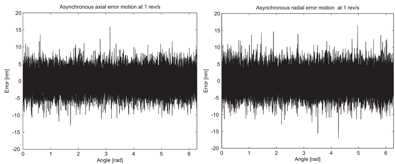
Figure 3.38: Axial and radial asynchronous error motion
To double check the radial error motion results of Figure 3.37, a multi-step measurement was performed. The reference sphere was measured again at the three speeds for 20 revolutions, but now also at three orientations spaced 120° apart. It should be noted that these steps are not exact, since no exact means of indexing was available at that time. As can be seen from the measurement results in the coming paragraphs, the resulting errors are probably smaller than what Figure 3.37 (right) suggests. Figure 3.39 (top left) shows the averages of the 9 measurements. Subtracting the shifted sphere profile from these measurements does not give a repeatable radial error motion result, again indicating that the radial error motion results shown in Figure 3.37 (right) are unreliable.
Radial capacitive probe (1st order removed) Difference with mean
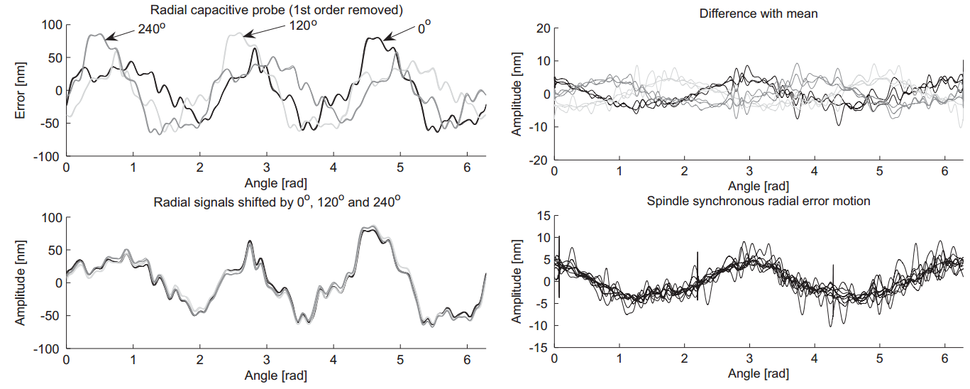
Figure 3.39: Spindle radial synchronous error motion from multi-step method
In the multi-step measurement signals (Figure 3.39, top left), the sphere roundness profile component is shifted by 0°, 120° and 240° while the synchronous error motion component has a fixed orientation. As can be seen, the profiles look very much alike, indicating that the error motion component is small. Figure 3.39 (bottom left) shows the measurements shifted back by 0°, 120° and 240° degrees respectively. Figure 3.39 (top right) shows the difference of these measurements with their collective average. This difference is equal to the synchronous error motion shifted by 0°, 120° and 240°. Again, much similarity can be seen, and shifting these signals back results in the radial synchronous error motion. The 2nd order component in this profile has a PV value of about 12 nm.
The large discrepancy between the NMi calibration and the multi-step method is probably due to the different filtering properties of the contact stylus that was used for the reference sphere calibration and the capacitive probe that was used in the multistep. It is concluded that the axial and radial error motion results shown in Figure 3.37 and Figure 3.39 are the most reliable. After installation to the base and bolting on the product mounting table, the spindle still shows excellent error motion properties.
3.4 Z-stage
The Z-stages provides 6 degrees of freedom to the Ψ-axis. It should constrain these such that sub-m uncertainty is achieved at the probe tip. This especially concerns its y, ϕ, ψand-direction; the r and z-direction are measured by the interferometry system on the Ψ-axis rotor. The Z-stage is aligned with three bearings to a vertical plane, constraining it in y, ϕ and -direction. The other three degrees of freedom are constrained by the R-stage. Two bearings along the side of the main tube constrain the r and ψ-direction, and the z-direction is constrained by the Z-motor or Z-brake. The Z-stage front and back view are shown in Figure 3.40. The Z-stage consists of a position frame (1), a preload frame (2) and a motor (3), brake (4) and linear scale (5). Further, a weight compensation (6), connected to the R-stage (7), and an emergency brake (not shown) are applied. The main components of the Z-stage will be explained in the coming sections.

Figure 3.40: Z-stage assembly
3.4.1 Position frame
The basis of the Z-stage position frame is the vertical tube that is straight guided on its sides by two air bearing pairs on the R-stage. Main characteristic for the material selection is a high specific stiffness, to obtain high eigenfrequencies but also because every kilogram has to be weight compensated. Further, a high hardness is desired to enable grinding and lapping of the air bearing faces. As can be seen in Table 4.1, Silicon Carbide is the best material here again, but Alumina is a good second. This is more common and therefore is available in more cross-sections, has a shorter lead time and has a lower cost.
The Al2O3 tube (1) has outer dimensions of 150.5 x 155 mm, a wall thickness of 15 mm and a mass of 29 kg. The guidance face (2) and preload face (3) are lapped to a straightness of less than 2 m. Holes are provided in the front and backside for connecting the preload frame and the top air bearing (Figure 3.41).
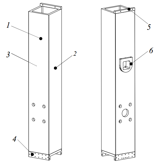
Figure 3.41: Z-stage Alumina tube with bonded interfaces
Three metal interfaces (4-6) are bonded to the ceramic tube. Due to the large difference in thermal expansion coefficient, special alloys such as VaconTM, KovarTM or NiloTM (www11) that also have an α of almost 6 m/m/K are sometimes used. These metals are hard to obtain and have high cost, and are only required when large temperature differences are expected.
The difference in expansion between steel and Al2O3 is 6 m/m/K, or 0.45 m/K at the corners of the 150 mm tube. Araldite 2020 adhesive has an E-modulus of 2⋅109 N/m2, a shear modulus G of ~6⋅108 N/m2 and a shear strength of approximately 25 N/mm2. When the Al2O3 and steel parts are supposed to be rigidly expanding (Figure 3.42, left), a temperature change of 2.2 K would break a 0.025 mm thick layer of adhesive. Larger temperature shifts must however be expected, for instance during transport.
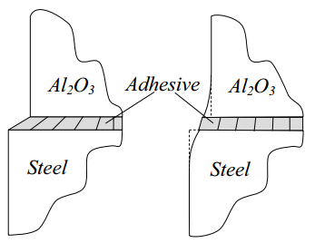
Figure 3.42: Deformation of the adhesive layer under thermal expansion
The steel and Al2O3, however, are not rigid (Figure 3.42, right). For the bottom interface, the shear stress of 25 N/mm2 causes deformations in the steel and Al2O3 of about 7 and 5 m, respectively. Together with the allowable deformation of the adhesive of 1 m, the total expansion difference can be 13 m. This occurs at a (homogeneous) temperature shift of 29 K, which is a safe margin.
To mount the ∅150 mm top bearing (1 in Figure 3.43), a steel cup (2) is bonded into the ceramic tube. A ring (3) is bonded on the inside to create a symmetrical connection. The cardanic hinge (4) of the bearing is bolted into this cup. The cup has a conical socket at the backside to connect the force frame (5) via a sphere (6), and the topside of the cup is flattened to mount the Z-stage motor and brake strip (7) as will be further explained in section 3.4.4. This way, the bearing has a stiff connection to the ceramic tube, while the preload force can be applied directly behind the bearing without distorting the position frame.

Figure 3.43: Connection of the top bearing
At the steel interface on the bottom of the ceramic tube (1 in Figure 3.44), the two lower ∅100 mm bearings are to be attached, together with the mount for the Ψ-axis and the Z-stage optics assembly. The two bearings and their cardanic hinges are mounted to an aluminium hollow bridge. This bridge consists of 4 parts: a centre part (2), two arms (3, 4) and a bottom cover plate (5). The two arms are bolted to the centre part and form a closed box together with the cover plate. The preload frame (6) will be mounted inside (but separated from) this box, as is further explained in section 3.4.2.
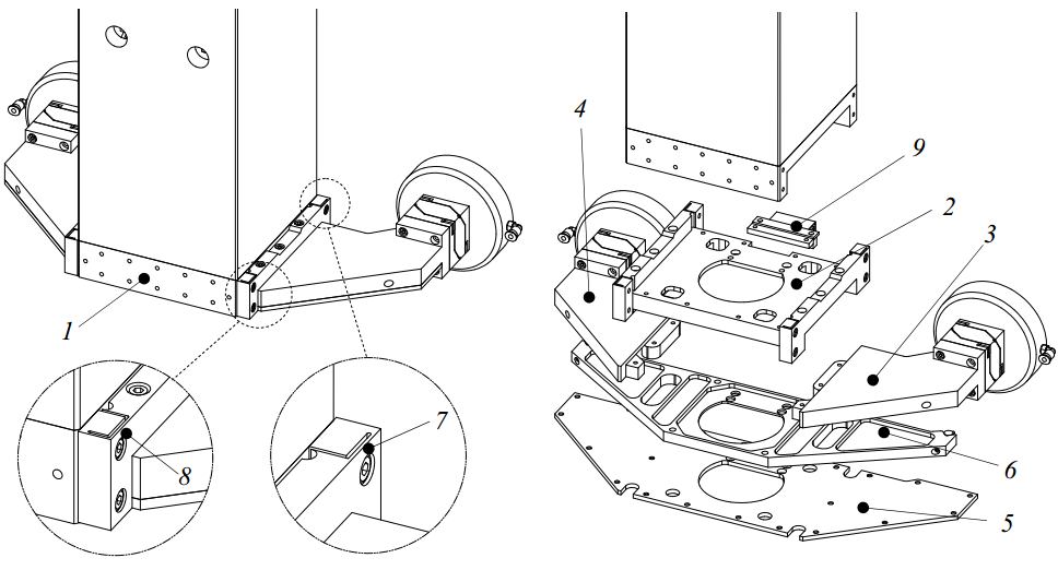
Figure 3.44: Bridge carrying the lower bearings
The y-position of the Ψ-axis and thus of the probe tip is determined by the y-position of the bottom of the ceramic tube, which gets its y-position from the two bearings. To avoid hysteresis between the bridge and the interface, the aluminium centre part of the bridge is attached to the steel interface using two leaf springs (7) and two folded leaf springs (8), manufactured into the centre part by wire EDM. A folded leaf spring (9) constrains the remaining sideways degree of freedom. This way thermal snapping due to the difference in thermal expansion coefficient is avoided, and the route from the ceramic tube to the two bearings in y-direction is shortest.
The 2 ∅100 mm bearings are spaced 350 mm apart, and the distance between these bearings and the top ∅150 mm bearing is 595 mm. The ∅100 mm bearings with the cardanic hinges each have a stiffness of 1⋅108 N/m, and the ∅150 mm bearing has a stiffness of 1.6⋅108 N/m. Supposing the Z-stage as rigid, this gives a stiffness cZ,y of 3.6⋅108 N/m, kZ,ϕ of 3.2⋅107 Nm/rad, and kZ, of 6.1⋅106 Nm/rad. The 2 ∅125 mm
bearings on the side of the ceramic tube have a stiffness of 1.3⋅108 N/m and are spaced 595 mm apart. This gives a stiffness between the R-stage and Z-stage in r and ψ-direction of cZ,r = 2.6⋅108 N/m and kZ,ψ = 2.3⋅107 Nm/rad.
The total mass of the Z-stage position frame is 35 kg, including the position determining bearings. These bearings also have to support the preload frame, the Ψaxis and the probe. The total mass, inertia and resulting rigid body modes of the Zstage assembly will be explained in section 3.4.6.
The Z-stage preload frame will be mounted directly onto the bearings, as will be explained in the next section. This mainly lowers the rigid-body mode frequencies of the Z-stage, but does not influence the flexural body modes of the position frame. The 1st and 2nd flexural eigenfrequencies of the Z-stage are bending modes of the bridge in phase and counter phase at 367 Hz and 381 Hz (Figure 3.45). The 3rd eigenfrequency is in-plane bending of the bridge at 600 Hz, where the 15 kg of Ψ-axis mass is taken into account.
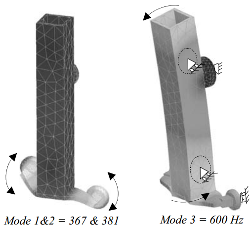
Figure 3.45: Z-stage position frame eigenmodes
Figure 3.46 shows the partially realized Z-stage position frame with the cup and the motor mount on the left. The assembled bridge, with the two ∅100 mm bearings, is shown on the right.

Figure 3.46: Alumina Z-stage tube and lower bearings bridge
3.4.2 Preload frame
The ∅150 mm bearing requires 2000 N and the ∅100 mm bearings require 1000 N. The Z-stage preload frame applies the preload forces while preventing distortion of the Z-stage position frame. The frame consists of a steel tube (1) inside the ceramic tube (2), as shown in Figure 3.47. The central pull tube (3) is bolted to this vertical tube with four spacers (4) extending through holes in the ceramic tube. A box structure (5) at the end of the pull tube carries the preload bearings. The vertical tube is a welded fabrication. The top part (6) contains a conical socket that is aligned with the conical socket in the cup (8), shown in Figure 3.43. A 25 mm hardened steel sphere (9) in between constrains the 3 translations of the preload frame, relative to the position frame. As will be shown later, the motor and brake are also connected to the cup (8), constraining the vertical position of the position and preload frame in a short and direct route.
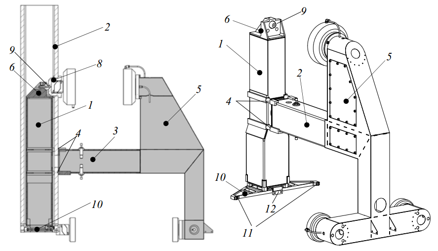
Figure 3.47: Z-stage preload frame
At the bottom, a plate (10) that preloads the bottom bearings via 2 contact cylinders (11) is bolted to the vertical tube. This plate is mounted inside the hollow bridge of Figure 3.44 and constrains the ϕ and -direction of the preload frame. A folded leaf spring (12), attached to the lower interface on the ceramic tube, constrains the remaining ψ-direction.
To mount the Z-stage into the R-stage, the ceramic tube with the vertical preload frame tube are lowered in from the top. Next, the bridge with the preload plate inside, together with the two bearings, is installed. Then, the backside part of the preload frame is assembled from the backside of the machine, and bolted to the vertical preload tube through holes in the front and the backside of the ceramic tube. Besides the sphere, two cylinders and the folded leaf spring that constrain the six degrees of freedom, the preload frame does not contact the position frame.
The wall thickness of the vertical and horizontal tubes is 4 mm and the box thickness is 1 mm. As can also be seen in Figure 3.47, all plates extend into the opposite plate at sharp corners, to increase the torsional stiffness of the box. The box is welded from lasercut sheets using plug welding. The maximum stress is 60 N/mm2 and the maximum deflection is 0.38 mm, as shown in Figure 3.48.
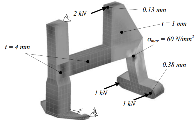
Figure 3.48: Z-stage force frame deformation due to preload forces
The combined mass of the preload bearings and pistons is 4 kg, which has to be constrained by torsion and bending of the vertical and horizontal tube. The relatively large thickness of 4 mm is required to constrain this mass that is far away from the mounting points. The first mode (Figure 3.49) is torsion in the vertical tube, causing the backside to swing from left to right at 84 Hz. The second mode is bending in the pull tube, causing the backside to swing up and down at 105 Hz. The total preload frame mass is 22.6 kg, including the preload bearings and pistons.
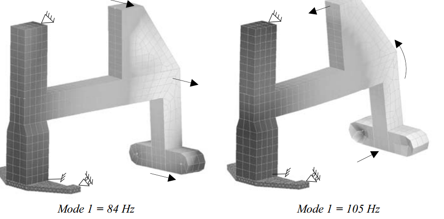
Figure 3.49: Z-stage preload frame eigenmodes
Figure 3.50 shows the preload frame and the lower plate with the contact cylinders inside the hollow aluminium bridge (bottom cover plate removed).
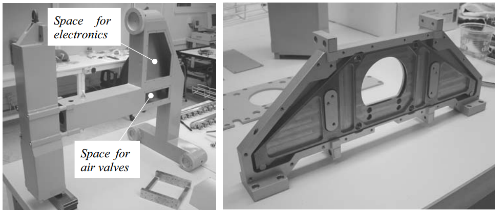
Figure 3.50: Z-stage preload frame
As will be explained in Chapter 5, the probe electronics should be close to the probe to minimize capacity of the cables. They are therefore mounted into the backside box of the Z-stage. From there BNC cables transport the ±10 V signals to the data acquisition system. Inside the horizontal tube of the preload frame, air valves and the solenoid valve for the Ψ-axis brake are mounted. This limits the number of air hoses that have to move along with the Z-stage.
With the two valves, the air of the Ψ-axis and the air to the fixed front bearings of the Z-stage can be closed. The air pressure on the preload bearings and pistons remains, clamping the Z-stage to the vertical base plate. This is useful for testing of the machine since it eliminates the R- and Z-bearings and brakes from the structural loop.
3.4.3 Weight compensation
The total vertically moving mass is about 85 kg. To avoid the motor having to continuously lift this weight and thereby forming a disturbing heat load, the weight is compensated. Also, the brake can be much lighter if no weight is to be held up. Friction must be minimal to avoid virtual play that limits the positioning resolution. Several methods can be applied for generating a constant upward force over a large stroke (Frank et al., 2005).
Most common is balancing with a mass via a pulley, using a wire or strip (Figure 3.51A). This doubles the moving mass and introduces an extra body of which five degrees of freedom have to be constrained relative to the R-stage. The friction introduced by the pulley may be acceptable, but introducing another 85 kg of moving mass to the machine is not preferred.
A Tensator® spring (www18) generates a constant force over a considerable stroke
(Figure 3.51B). It is, however, not capable of providing 850 N over 150 mm. The rolling of the windings further also is not frictionless. It is also difficult to adjust to the increasing weight during assembly and to finetune when assembly of the machine is completed.
An air piston (Figure 3.51C) has a much higher force density. A ∅52 mm piston at 4 bar delivers the required force. Sealing the gap between cylinder wall and piston usually introduces unacceptable amounts of friction. Using air bearings for guidance and a narrow gap as a seal eliminates the friction, but has very tight manufacturing tolerances.
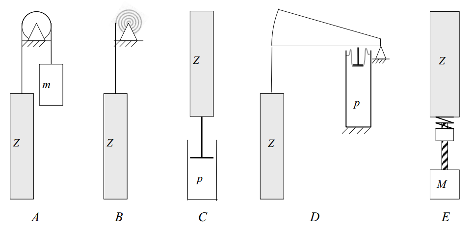
Figure 3.51: Weight compensation concepts
To avoid the air bearing, one may also use a pressurized volume with a rolling membrane and a lever (Figure 3.51D). If the pressurized volume is large enough, the force is almost constant over the range. The stroke of the membrane is generally limited to a few tens of millimeters, requiring a lever ratio in the order of 1:10. The piston area or air pressure thus have to be increased by one order of magnitude to compensate 85 kg over 150 mm this way, which is not practical.
A more mechatronic solution would be to drive a lead screw with a motor (Figure 3.51E). With a spring between the nut and the Z-stage, it can still move frictionless. A control system should maintain a constant force in the spring. Lifting 85 kg over 150 mm requires 125 J to be inserted in for instance 1 second. Quite a powerful motor is thus required, and a new heat source would be introduced into the machine.
An air bearing piston is chosen to be applied. Since a single round bore could not provide enough surface area within the available volume, a rectangular piston (70 x 30 mm) was chosen (Figure 3.52). The piston (1) has 12 porous air bearing plugs (2) similar to those used in the Ψ-axis (see section 3.6.1). The individual air bearing pads
(3) are separated by atmospheric grooves (4). The air bearings are fed from the pressurized volume (5) through holes (6) in the bottom of the piston. The normalized air consumption of the air bearing is approximately 0.8 l/min.

Figure 3.52: Z-stage weight compensation
The entire available volume is used as an air chamber to minimize the relative volume reduction when the piston is moving. This is done by machining the bore (7) and chambers (8), interconnected by holes (9) from a solid block of aluminium and covering it with a lid (10). The piston was then made to fit the bore. A passive precision pressure regulator is used to finetune the pressure to the actual mass of the Z-stage and to (passively) keep this pressure constant. Some hysteresis will be present in this valve. In combination with the tuning error this will give a remaining force that is to be countered by the motor.
The pressure chamber is sealed with a parallel gap resistance (11). The resistance R of a parallel gap with width w, gap height h and length l, and dynamic viscosity η is
R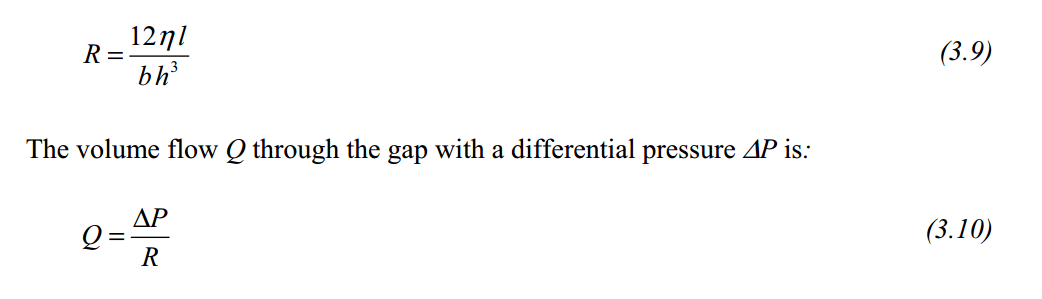
The air bearing gap h is 7 m. The 10 mm long parallel gap seals the pressure chamber with a circumference of 200 mm. The dynamic viscosity η = 17⋅10-6 Pa.s. This results in a resistance R of 3.0⋅1010 Pa.s/m3. With a pressure inside the cylinder of 4 bar, the normalized leakage is equal to 3.2 l/min. The leakage is a function of the 3rd power of the gap height, so small manufacturing tolerances or for instance scratches cause a large increase in the leakage. The total normalized air consumption of the weight compensation is 4 l/min.
The combined centre of gravity of the Z-stage, Ψ-axis, probe and Z-stage optics is located at the backside of the ceramic tube, as shown in Figure 3.53. The weight compensation system is nearly aligned with this centre of gravity. The piston rod is connected to the Z-stage preload frame and the pressure chamber is connected to the R-stage preload frame as shown later in section 3.5.2. Connecting the weight compensation to the preload frames minimizes varying deflection in the position frames due to varying compensation forces.
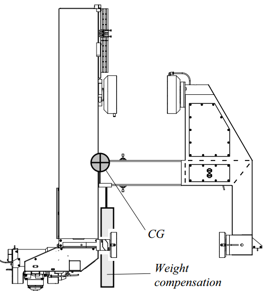
Figure 3.53: Z-stage centre of gravity and weight compensation location
Figure 3.54 shows five measured hysteresis loops after careful alignment, obtained by applying a triangular force as a disturbance to a pure gain controller. The controller stiffness has been subtracted from this graph. The discontinuity in the force in combination with the absence of damping causes the oscillations. Around the centre of the stroke (z = 40 mm), the residual friction is about 1 N and at the ends of the stroke (z = -20 mm and z = 120 mm) this is 4 N and 5.5 N, respectively.
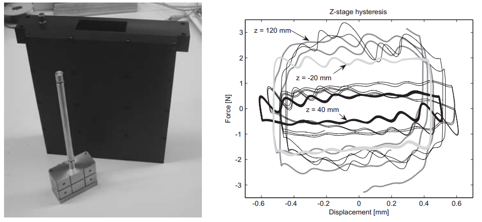
Figure 3.54: Weight compensation of Figure 3.52 and its hysteresis loop
3.4.4 Motor, brake and linear scale
For optimal dynamic behaviour, the motor should be aligned with the centre of gravity. The centre of gravity of the combined Z-stage, Ψ-axis and probe is situated approximately on the back face of the ceramic tube as shown in Figure 3.53. An aluminium plate (1) is hereto bolted to the cup and the interface block on top of the ceramic tube (Figure 3.55). Hinges (2, 3) are machined into the plate to cope with the difference in expansion coefficient. The magnet yokes (4) of the motor are bolted to this plate, and the coils (5) are mounted to the R-stage position frame (6). Placing the motor this high, keeps the heat source away from the metrology loop. Next to the motor magnets, the brake strip (7) is mounted. The motor plate is bolted directly to the interface cup, which provides a stiff coupling between the motor and brake and the Z-stage position and preload frame. The brake clamp (8), as discussed in section 3.1.2, is mounted to the R-stage position frame, next to the motor coils.

Figure 3.55: Z-stage motor and brake
The remaining friction and tuning error of the weight compensation was measured to vary between 1 and 5.5 N along the stroke. The selected Tecnotion UL3 ironless linear motor has a motor constant of 97 N2/W, a peak force of 240 N and a continuous force of 35 N. This particular motor has the highest motor constant and thus the least power dissipation to fit the available volume.
When measuring circular tracks, the amount of Z-stage work depends on the height variation of the product. Making a 1 mm step in 1 s with a 3rd order profile requires a peak acceleration of 6.3 mm/s2, which is equal to a peak force of 0.5 N on 85 kg. When opening the brake, the residual weight compensation error thus determines the required force. Generating 5 N during 1 s requires 0.25 J, and for 250 steps during 15 minutes 62 J. When assuming ideal operation of the amplifier, this is a negligible average heat dissipation of 69 mW.
An optical linear scale is used for position feedback (Figure 3.56). The Heidenhain LIP481R Zerodur scale is bonded to the front of the Al2O3 tube via small flexure blocks to allow differences in thermal expansion. The bottom block, which is closest to the probe, has no flexure and determines the vertical position of the scale. The mounting and alignment mechanism of the read head on the R-stage position frame will be discussed in section 3.5.4.

The linear scale is positioned relatively far from the motor, which may cause control instabilities. The loop between motor and linear scale is stiff, consisting of only the motor plate and the Alumina tube. The motor drives the Z-stage through its centre of gravity, so parasitic rotations will be small. This non-collocated setup is preferred to have the Z-position measurement close to the probe.
The brake, motor and scale are shown in Figure 3.57. Two pairs of limit switches are also shown, for detecting the ends of the Z-stage stroke. These will be further discussed in Chapter 6.

Figure 3.57: Z-stage brake (left), motor (centre) and linear scale (right)
3.4.5 Emergency brake
When air pressure fails, the weight compensation pressure will also drop. Since the brake is not able to hold the 85 kg mass, the Z-stage will plummet down. Shock absorbers are present to dampen this, but when the probe is oriented vertically, it will crash into the table or into a product that is rotating underneath. To prevent this, an emergency brake system is included. A pressure vessel is present, giving a few minutes of spare pressure supply.
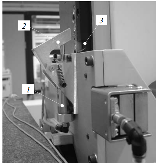
Figure 3.58: Z-stage emergency brake
If an electronic or passive sensor detects an air pressure failure, a series of valves diverts a slightly higher pressure to the weight compensation, which causes the Zstage to be swiftly lifted. In the mean time, the pressure also drops from the spring preloaded piston (1) shown in Figure 3.58. This causes the lever (2) to lock into the slot (3) in the Z-stage motor mount, locking it at the top position. Tests have shown that this takes less than a second, which is probably fast enough to save the probe. This procedure is executed when the air pressure fails, when the control software stops responding, when the emergency stop is pressed or when electric power fails.
3.4.6 Z-stage assembly
The Z-stage is shown in Figure 3.59 as it is mounted in the R-stage. The ceramic tube with the preload tube inside was lowered into the R-stage from the top, after which the lower bearing bridge was bolted on. Next, the central pull tube and the backside box were bolted on. The alignment of the Z-stage will be discussed in section 3.7, along with the assembly of the rest of the motion system.
Figure 3.59: Z-stage assembly
Table 3.2 summarizes the (theoretical) properties of the Z-stage. The Ψ-axis, probe and Z-stage optics assembly have been taken into account in the mass and inertia calculations. The total mass is 80 kg, and about 5 kg is added for cables and the probe electronics. The vertical stiffness cZ,z is the brake stiffness only, so the stiffness of the Z-stage relative to the R-stage. This is also the case for cZ,y and kZ,ψ. The complete structural loop stiffness from probe tip to base will also be explained in section 3.7.
Experimental validation will be done in section 3.8.2.
| i |
cZ,i [N/m] |
mZ,i [kg] |
fZ,i [Hz] |
|
i |
kZ,i [Nm/rad] |
JZ,i [kgm2] |
fZ,i [Hz] |
| r |
2.6⋅108 |
85 |
278 |
ϕ |
3.2⋅107 |
12.1 |
259 |
|
| y |
3.6⋅108 |
327 |
ψ |
2.3⋅107 |
9.1 |
253 |
||
| z (brake) |
5⋅107 |
122 |
θ |
6.1⋅106 |
3.6 |
207 |
Table 3.2: Z-stage assembly theoretical rigid body property summary
3.5 R-stage
The R-stage constrains the r, ψ and z degrees of freedom of the Z-stage, so it must provide high stiffness in these directions. Since the r and z-position are measured directly at the Ψ-axis rotor, especially the ψ-direction must be provided with high repeatability. Since the Z-stage is directly aligned to the base in y, ϕ and θ-direction, errors of the R-stage in these directions do not influence the position of the probe tip. The R-stage, however, also carries the scale read heads and R-stage optics assembly, of which the alignment is critical. The other three degrees of freedom of the R-stage should thus be constrained with high stiffness and repeatability as well.
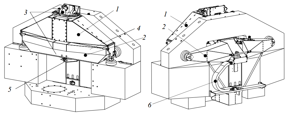
Figure 3.60: R-stage assembly
Figure 3.60 shows the front and back view of the R-stage assembly. In the coming sections the main components will be explained, starting with the position frame (1), the preload frame (2) and the Z-stage r and ψ constraining bearings (3). Next, the Rstage motor and brake (4) and linear scale (5) will be explained, followed by the cable guidance (6).
3.5.1 Position frame
The R-stage position frame (Figure 3.61) has two horizontal bearings (1 and 2) at the front constraining the z and ψ-direction, in the same plane as the ceramic tube axis of the Z-stage. Two plates extend backwards to two horizontal bearings (3 and 4) at the backside that constrain the ϕ-direction. The position frame has a torsional degree of freedom to prevent overconstraining. It is hereto built from two box structures (5 and 6) on the left and right, which are connected by a U-shaped bridge (7). The plate (8) and strut (9) were added to increase the bending stiffness in the horizontal plane, and also to provide a mounting point for the Z-stage motor and brake. Two horizontal bearings (10 and 11) against the vertical base plane constrain the y and-direction to the same plane as to which the Z-stage is aligned.
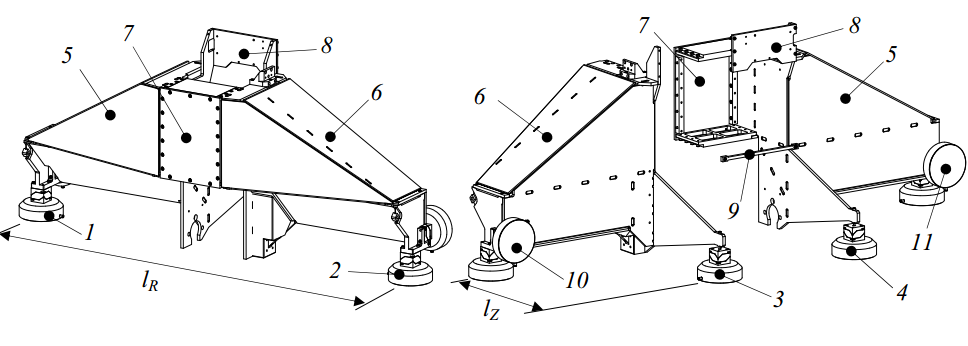
Figure 3.61: R-stage position frame
The ∅150 mm bearings and cardanic hinges have an in series stiffness of 1.6⋅108 N/m. The distance lR between bearing pairs (1) and (2), and (10) and (11) is 1.4 m. The distance lZ between these bearing pairs and bearings (3) and (4) is 470 mm. This gives a stiffness in y-direction of cR,y = 3.2⋅108 N/m, in z-direction of cR,z = 6.4⋅108 N/m, a tilting stiffness in ψ and θ-direction of kR,ψ = kR,θ = 1.6⋅108 Nm/rad and a tilting stiffness in ϕ-direction of kR,ϕ = 3.5⋅107 Nm/rad.
The R-stage position frame is constructed from 10 mm thick aluminium plate, mainly for its high thermal conductivity and good machinability. These plates can be connected by bolting, bonding or welding. Bolting requires tight tolerances and many threaded holes in the (inclined) side faces of the plates. The limited contact area between the plates forms a high heat flow resistance, which increases thermal gradients over the structure. Main advantage is, however, that the stage can be disassembled in case of damage or a design change. Bonding requires narrow bond gaps to create high stiffness. This requires high dimensional tolerances, adhesive forms a resistance to heat flux and disassembly is not possible. Welding requires less tight dimensional tolerances since small gaps can be closed with filler material when welding. Welds have high stiffness and good conductivity, but disassembly is not possible. Due to the high conductivity, the structure has to be pre-heated to create good welds. During welding, much heat is further brought in very locally. This may lead to distortions and internal stresses during cooling. Annealing is applied to reduce these, but this may further increase distortion. Machining the interfaces to other parts after welding and annealing solves this problem.
The left and right boxes (Figure 3.62) consist of a vertical back plate (1) to which the vertical plate (2) containing the support to the backside bearing is joined. A horizontal plate (3) is mounted in between these boxes. The inclined top plate (4) and front plate (5) form a triangular box. Another plate (6) is added at 45° on the bottom to form a horizontal triangular tube. A stiffening plate (7) is added inside the top box to stiffen the horizontal plate where the 45° plate is attached. After the box structure has been welded, the interface faces were machined and the end plate (8) was bolted to it to connect the bearings.

Figure 3.62: R-stage position frame box structure
The outside corners (L-connections) of the box are made by adding a chamfer, such that the weld is at the intersection of the plate centre lines (A in Figure 3.63). At the end plate of the triangular tube, plate 3 and 4 are welded and the end plate is bolted such that the plate mid-planes intersect (B). All T-joints are made by plug welding (C), where the plug is slightly recessed to have the weld at the mid-plane and reduce the weld bulging out of the slot. At the intersection of plate 3, 6 and 7 an alternate combination of joint A and C has been made (D).
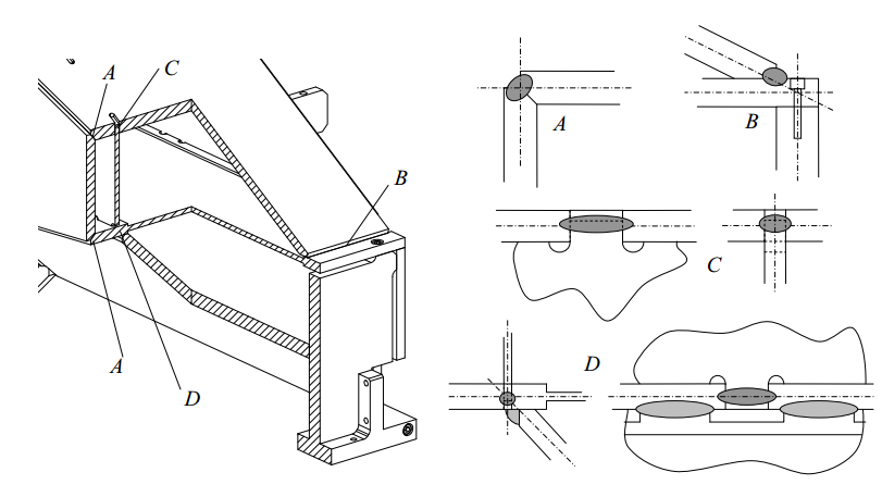
Figure 3.63: R-stage position frame weld connections
The total mass of the R-stage position frame is about 68 kg. Figure 3.64 shows the first and second eigenfrequency, at 139 Hz and 227 Hz respectively. In the first mode, the stage is mainly rotating in ϕ-direction, which does not influence the Z-stage position since this makes the bearings that guide the Z-stage, slide over the sides of the ceramic tube. The second mode is bending of the stage, which causes a ψ-rotation of the Z-stage since the two bearings that guide it move in r-direction in counter phase. The calculated stiffness in z-direction at the Z-stage brake clamp mounting position is 7.1⋅107 N/m. The tilting stiffness in ψ-direction at the Z-stage bearing points is 1.15⋅107 Nm/rad.
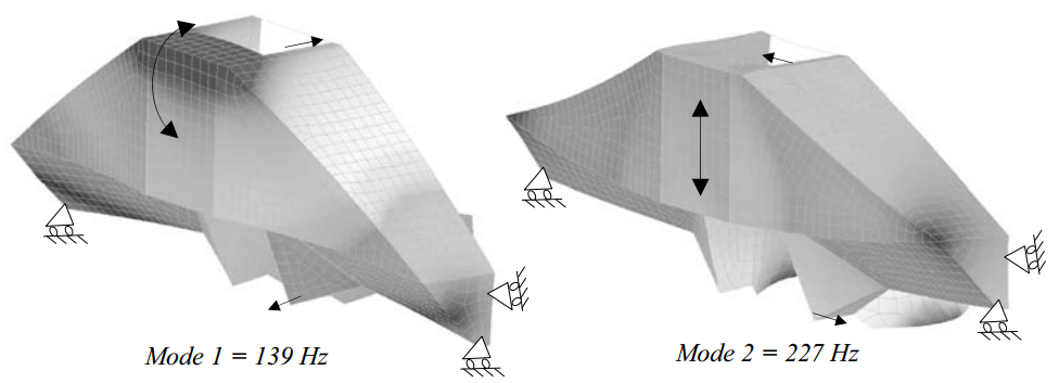
Figure 3.64: R-stage position frame eigenmodes
The structure is designed such that it can be completely assembled jig less before being welded, to minimize distortions. Figure 3.65 shows the assembly and welding of an R-stage position frame box structure. The assembled position frame is shown before painting.

Figure 3.65: R-stage position frame welding
3.5.2 Preload frame
Each ∅150 mm bearing must be preloaded with 2 kN, with minimal distortion of the R-stage position frame. The combined mass of all stages, which is about 275 kg, partially preloads the horizontal bearings (1-4) as shown in Figure 3.66. In this figure, the end plates (5 and 6) of the R-stage position frame are also shown. The centre of mass is located in the front half of the stage, resulting in a higher preload of the two front bearings (1 and 2). The four horizontal bearings (1 – 4) combined require 8 kN, of which 2750 N is provided by the stage mass, and the remaining 5250 N should be provided by the horizontal preload bearings. This is done by two ∅150 mm bearings (7), each with a piston that generates 2625 N, at the cost of a slightly smaller air gap.
The two bearings with the highest load capacity as measured in Figure 3.2 are used here. These bearings are positioned such that the resulting force vector of the mass and the preload bearings results in 2 kN at each position determining horizontal bearing.
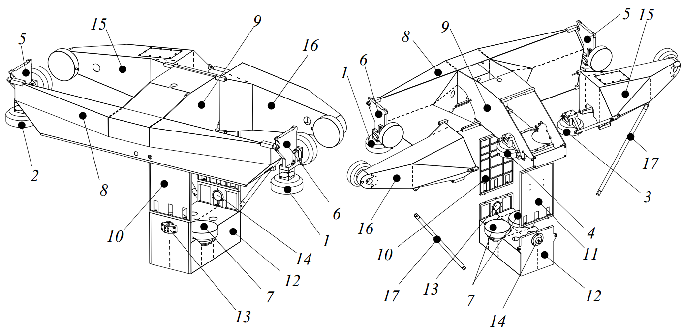
Figure 3.66: R-stage preload frame assembly
The preload frame has to connect these bearings to the R-stage position frame and deliver the forces directly onto the bearings to minimize distortion. It hereto consists of a horizontal front beam (8), which is connected to the endplates of the position frame with two shoulder bolts. A flexure at these two points constrains the y, z, ψ and θ-degrees of freedom. From this beam, a tube (9) extends backwards through the gap in the base, which has its side faces aligned with the two fixed bearings (3 and 4) at the backside. This constrains the ϕ-degree of freedom. The r-direction will be constrained by the motor and brake, as shown in section 3.5.4. Several cut-outs have been made to allow space for the Z-stage and its bearings, and to introduce a torsional degree of freedom just as with the position frame.
From the central tube (9), two plates (10 and 11) extend downwards to a box structure (12) that carries the two preload bearings (7) and pistons. The front plate runs through the slit between the bottom and middle base block. To prevent parallelogram motion, two ∅50 mm bearings (13 and 14) are added, the front one fixed, the backside one with a piston.
From the central tube, two arms (15 and 16) extend to the left and right, carrying the horizontal preload bearings and pistons. Two support struts (17) provide stiffness in vertical direction to the arms.
The preload frame is mainly constructed of 1 mm thick steel sheets. Only the vertical sides of the central tube are 4 mm thick. Steel is chosen here because of the high load the frame has to withstand, and for the better weldability of thin sheets compared to Aluminium. The total mass of this frame is 55 kg. Figure 3.67 shows the 1st and 2nd eigenfrequency at 68 Hz and 73 Hz respectively. In practice, the pistons will provide some stiffness and damping, increasing the eigenfrequencies. The preload forces cause a maximum deflection of 0.56 mm at the ends of the arms on the backside, and a stress of 240 N/mm2.
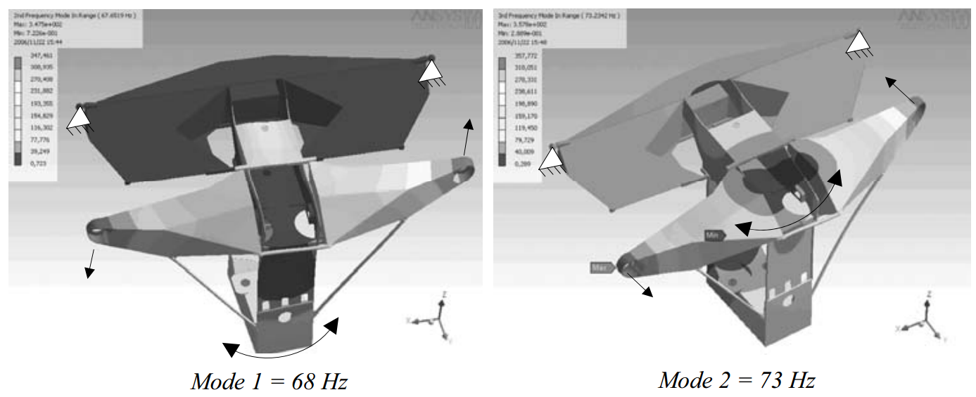
Figure 3.67: R-stage preload frame eigenmodes
The preload frame is constructed of 1 and 4 mm thick lasercut steel sheets. T-joints are made using plug welding, and L-joints are simply welded together. Figure 3.68 shows the bottom box assembled just before welding and the completed preload frame before paint.

Figure 3.68: R-stage preload frame realization
3.5.3 Z-stage tube bearings
The fixed ∅125 mm bearings that guide the Z-stage tube are attached to the right half of the R-stage position frame (Figure 3.69). A stiff arm (1) hereto extends from the Rstage position frame towards the lower position determining bearing (2). A bracket (3) is used to bolt the upper position determining bearing (4) to.
These bearings require a preload of 1500 N. The opposing preload bearing and piston are hereto mounted to a plate (5) that is bolted to the R-stage position frame, constraining only the in-plane degrees of freedom. At the upper bearings, the force loop is closed with a C-yoke (6). The lower bearings are bonded to two cups (7 and 8) which are connected with two pull rods (9) due to space constraints. In both cases the force loop is separated from the position frame this way.

Figure 3.69: Z-stage tube bearings
The lower Z-stage tube bearing assembly is hidden behind the R-stage preload frame. The visible preload bearing cup is shown in Figure 3.70 (left). The upper Z-stage tube bearing assembly with the C-yoke is shown in Figure 3.70 (right).
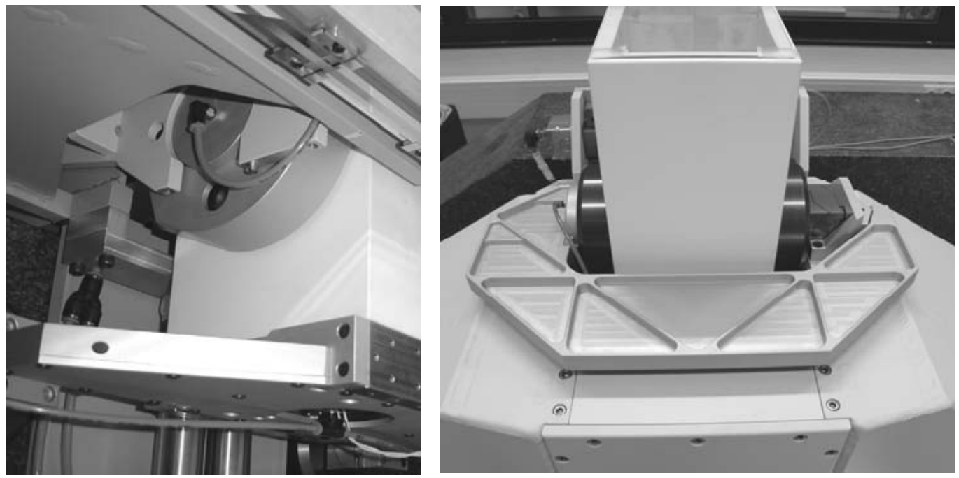
Figure 3.70: Z stage lower (left) and upper (right) tube bearings
3.5.4 Motor, brake and linear scale
The location of the centre of gravity of the stages, with the Z-stage in its middle position, is shown in Figure 3.71. The R-stage motor and brake are aligned with this point. Just as with the Z-stage, an aluminium plate (1) is bolted to the backside of the position frame. The magnet yoke (2) and the brake strip (3) are mounted to this plate. A folded leaf spring (4) constrains the r degree of freedom of the R-stage preload frame (5) to create a short route from motor and brake to this frame. The motor coils (6) and brake clamp (7) are mounted to a plate (8) that is bolted onto inserts in the top base block.

Figure 3.71: Stage assembly centre of gravity and R-stage motor and brake assembly
As explained in section 3.2.2, a maximum base tilt of 4.8 mrad is expected when the R-stage moves from left to right, requiring a counterforce from the R-stage motor of 13 N. Similar to the Z-stage, the R-stage makes 1 mm steps in 1 s between measurements. This requires a peak acceleration of 6 mm/s2, or 1.6 N. During these small steps, base tilt is negligible so only acceleration and deceleration forces are required from the motor. The mean force during this 3rd order profile is 1.4 N, requiring 0.02 J for a single step. For 250 steps in 15 minutes, this is equal to 5 J. Assuming ideal operation of the amplifier, the mean power dissipation is only 6 mW.
As with the Z-stage, a Heidenhain LIP481R linear scale is applied for feedback (Figure 3.72). This scale (1) is mounted onto the metrology frame (not shown) using flexure blocks similar to those used for the Z-stage. The R- and Z-stage read heads (2 and 3) are mounted to an aluminium arm (4) that extends from the R-stage position frame (5) via two alignment mechanisms (6 and 7). These monolithic mechanisms consist of a plate spring (8) that constrains three degrees of freedom, and three spring preloaded adjustment screws (9) to adjust tip, tilt and focus. Rotating the read head in its mounting hole provides the fourth degree of freedom required for proper alignment.
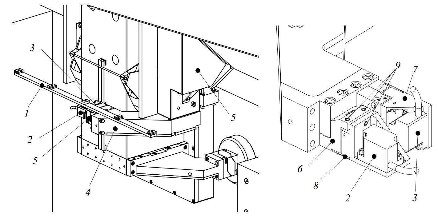
Figure 3.72: R-stage linear scale and read head alignment mechanisms (upside down)
Figure 3.73 shows the motor and brake as assembled on the machine. It also shows the R and Z scales with their read heads and alignment mechanisms. The R-stage optics assembly can also be seen in this figure, which is attached to the read-head arm on one side.
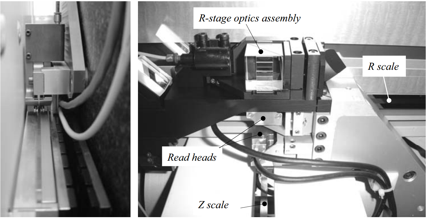
Figure 3.73: R-stage motor and brake, and linear scale read head assembly
3.5.5 Cable guidance
Measuring many parameters inside the machine has many cables, fibres and connectors as a consequence. The cables and air supply hoses mostly run inside the machine. 3 cables come from the probe and 5 from the Ψ-axis. They run through the Z-stage preload frame, together with the air supply hoses for the Z-stage and Ψ-axis bearings. The 2 probe signal cables are connected to the probe electronics in the backside of the Z-stage, and changed into 7 BNC cables and 2 power supply cables for the electronics. All 17 cables then come out at the bottom of the Z-stage preload frame and are guided through a cable chain onto the R-stage. From here, they are joined by about 10 more cables and air hoses from the R-stage and go into the R-stage cable chain to be transferred to a bar on the base. From here, the cables go to the electronics cabinet, together with the about 20 cables from the spindle, the lower metrology frame and the R-stage motor. This makes a total of 47 cables coming off the machine.
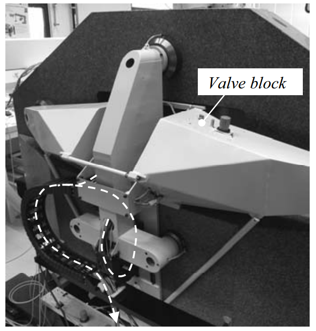
Figure 3.74: Cable chain assembly
The applied cable chains have rubber flexures instead of links, which reduces friction. In practice, the friction was found to be small enough to not influence the positioning resolution. The chains are connected to the preload frames. The R-stage cable chain has a minimum in its gravitational energy content when most of it is resting on the horizontal bar. This causes a small disturbing force on the R-stage. Mounting the cable chain horizontally would have kept the gravitational energy constant, but this was difficult due to space constraints.
Air hoses are thick and quite rigid. To minimise their disturbing forces, a single air line passes from the base to the R-stage and is split in a valve block (Figure 3.74) inside a backside arm of the preload frame. With this valve block, the R-stage bearings can be turned off to land the stage, the Z-brake can be operated manually and the air pressure of the weight compensation can be adjusted. One air hose passes from the R-stage to the Z-
stage and is split there as explained earlier. The Z-stage also has a valve block from which the air to the Ψ-axis and to the Z-stage front bearings can be closed for testing.
3.5.6 R-stage assembly
Figure 3.75 shows the R-stage with the Z-stage already installed. The backside was already shown in Figure 3.74. The position frame was mounted on the base first, after which the central T-section of the preload frame was installed from the front. Next the backside arms and other preload components and bearings were installed. A beam was used for mounting the R-scale temporarily, to allow for testing.
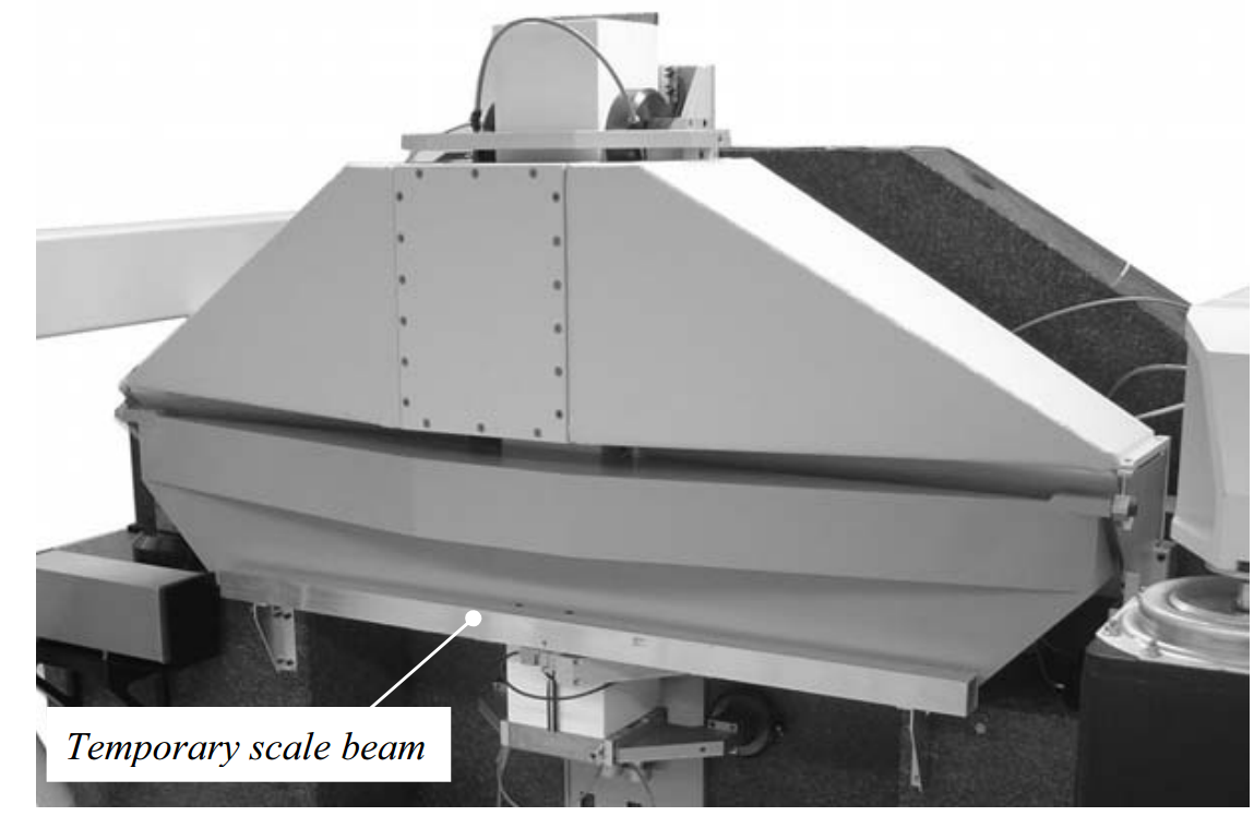
Figure 3.75: R-stage assembly
Table 3.3 summarizes the (theoretical) properties of the R-stage. The total mass of the R-stage is 174 kg. Since the Z-stage has its own bearings in y-direction, the mass to be calculated with in this direction is 174 kg. In the other directions, the combined R and Z-stage and Ψ-axis mass of 275 kg is used. For rotations, the Z-stage has its own bearings in ϕ and θ-direction, thus only the R-stage inertia is used here. In ψ-direction the R and Z-stage inertia are summed. Experimental validation will be done in section 3.8.2.
| i |
cR,i [N/m] |
mR,i [kg] |
fR,i [Hz] |
|
i |
kR,i [Nm/rad] |
JR,i [kgm2] |
fR,i [Hz] |
| r (brake) |
5⋅107 |
275 |
68 |
ϕ |
3.5⋅107 |
21.3 |
204 |
|
| y |
3.2⋅108 |
174 |
216 |
ψ |
1.6⋅108 |
50.7 |
283 |
|
| z |
6.4⋅108 |
275 |
243 |
θ |
1.6⋅108 |
35.3 |
339 |
Table 3.3: R-stage assembly theoretical rigid body property summary
3.6 Ψ-axis[1]
The Ψ-axis orients the probe perpendicular to the best-fit asphere. Part of the rotor is a cylindrical mirror on which the R- and Z-interferometer measure its radial rotor displacement relative to the metrology frame. An angle encoder measures the ψrotation of the rotor. Axial and tilt error motion cause a second order error, and are not measured in the metrology loop. Since sub-micrometer accuracy is desired for the axial and tilt error motion, a rotary air bearing has been designed. For measuring convex to concave optics, a range of motion from +45° to -45° is sufficient. To also enable the measurement of cylinders and to calibrate the vertical reference mirror, the range is increased to +90°. A nulling mirror has been added to home the probe, for which the range has been further increased to +120°. This brings the total range to +120° to -45°.
The Ψ-axis design consists of a housing (1) in which the bearing rings and rotor (2) are mounted, as shown in Figure 3.76. The rotor has a chamber (3) in which the probe is mounted. It further has a brushless DC motor (4), an encoder (5) and a brake (6). In the bearing housing, the cylinder lenses (7) are mounted for focussing the R and Zinterferometer beams onto the cylindrical mirror (8) centre line. A nulling target (9) is present for nulling the probe. The Ψ-axis is mounted on a thermally compensated mount (10). The Z-stage optics assembly is also attached to this mount. Each of these components will be further explained in the coming sections.

Figure 3.76: Ψ-axis assembly
3.6.1 Air bearing
The main dynamic force acting on the rotor is the reaction force of the acceleration of the probe objective. A single sided bearing (Figure 3.77, left) is preferred for the large stroke, but dynamic simulations (section 3.1.4) show that this would result in large tilts of the rotor, with large out-of-plane errors at the probe tip as a consequence. A symmetrical radial bearing layout converts these forces into radial error motion, which is measured by the metrology loop. The large range of ψ-motion of -45° – +120° requires a substantial part of the connecting housing between the two radial bearings to be open. The housing outer diameter is limited for measuring deeply concave optics (dotted line in Figure 3.77), which thus also limits the thrust bearing dimension and location.
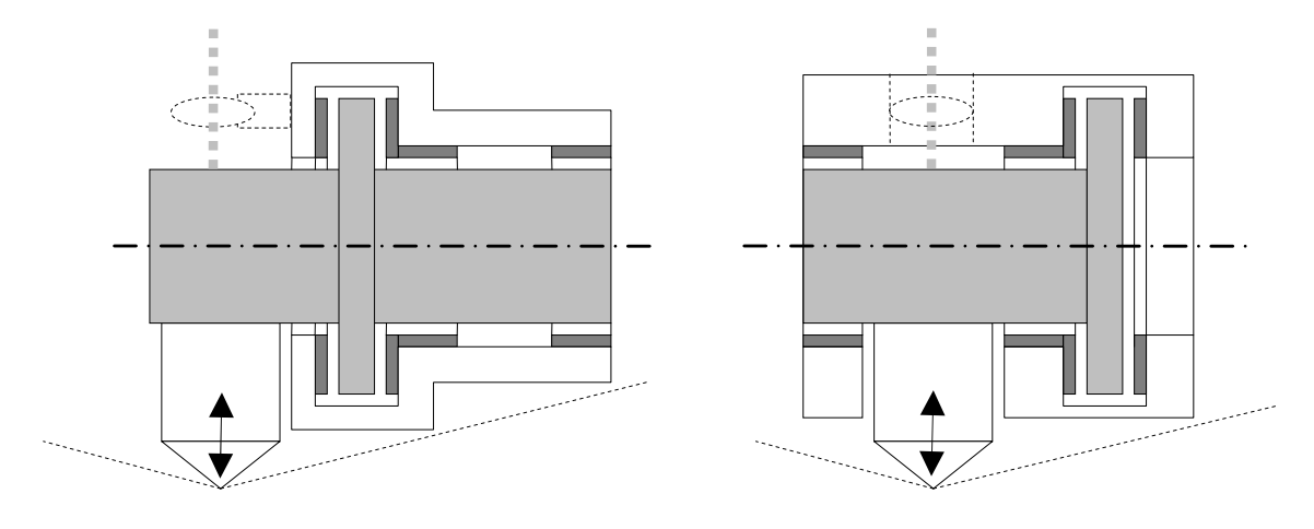
Figure 3.77: Ψ-axis bearing configurations
Porous plug air bearings
For a radial bearing to have stiffness, it must be composed of at least three individual bearing segments. This is generally done by supplying pressure to restrictions around the bearing. These restrictions can be small holes, in the order of tenths of millimeters (Figure 3.78A), in orifice or inherent compensated form (Holster, 1967; Van Beek, 2006). A chamber is sometimes added for extra load capacity and stiffness, but with the risk of pneumatic hammering. Small hole restrictions tend to get easily clogged with dirt particles. A porous graphite ring (Figure 3.78B) essentially has an infinite amount of restrictions. Machining this ring to the roundness tolerances required is very difficult, since graphite is a difficult material to work with. An intermediate solution is to use porous plugs as restrictions (Figure 3.78C). These may have the same flow resistance as the small holes, but have a much larger surface area which makes them much less vulnerable to dirt. The carrier ring in which they are mounted can be machined to the required roundness.
Figure 3.78: Air bearings with hole (A), porous (B) and porous plug (C) restrictions
A porous plug bearing unit can be characterized as shown in Figure 3.79, with the supply pressure PS, the pressure after the restriction PR, and the atmospheric pressure Pa. The porous plug has radius r1 and thickness s, and the bearing surface has radius r0. The bearing gap has height h.
Figure 3.79: Porous plug bearing and pressure distribution
The mass flow Mplug through the porous plug can be calculated with the permeability kp, the surface area Ap, the viscosity η, the gas constant R and temperature T (Van Beek, 2006):
Equalling the two mass flows results in:
Where the geometry factor g is:
g = π s (3.14)
r0 k Ap p 6 ln( )
r1
This results in the pressure after the restriction PR and the exact solution for the pressure distribution P(r):
PR = PS2 + gh P33 a2 and P r( )a 2 = PRa 2 − ln((r r0 / 11)) PPRa 2 −1 (3.15)
1+ gh P P ln r /r
The pressure distribution may also be approximated by a cone:
P r( ) = PR for r ≤ r1
and
(3.16)
P( )r P (r r1) for r1 r r0
Integrating the pressure over the area gives the load capacity Funit of a single bearing unit:
Funit = π(PR − Pa )(r02 − r12 + r r0 1 )
and (3.17)
Funit = π(PR − Pa )r02 when r1 r0
|
The stiffness cunit of a single bearing unit can now be calculated with
|
|
| c = − dFunit |
(3.18) |
unit dh
The permeability of the batch of carbon to be used was experimentally determined to be 5.5⋅10-15 m2 (Aerts, 2007). For a bearing unit radius of 10 mm, a plug diameter of 5 mm and a thickness 3 mm, the load capacity, stiffness and airflow are shown in Figure 3.80. Here, r1 is not supposed to be much smaller than r0.
Figure 3.80: Bearing unit load capacity, stiffness and flow rate
(r0 = 10 mm; r1 = 2.5 mm; s = 3 mm)
An air gap of 7 m is considered a good compromise between manufacturability, robustness to contamination and bearing properties. Figure 3.81 and Figure 3.82 show the influence of the porous plug dimensions on load capacity, stiffness and airflow for this gap height. A plug diameter of 5 mm and a thickness of 3 mm was selected for the Ψ-axis bearings, giving a load capacity of 29.6 N, a stiffness of 6.5⋅106 N/m and a normalized air consumption of 0.18 l/min per bearing unit.
Figure 3.81: Load capacity and stiffness as a function of the plug dimensions at 7 m gap height
Figure 3.82: Flow rate as function of plug dimensions at 7 m gap height
Axial bearing properties
The designed radial and thrust bearings consist of 18 bearing units. For the axial bearings this has 18 times the properties of an individual unit, or cax = 1.2⋅108 N/m, Fax = 533 N and Qax = 3.2 l/min (normalized). Since the thrust bearing will be form closed, stiffness is doubled to cΨ,ax = 2.4⋅108 N/m.
To verify the bearing properties, an axial bearing was made as shown in Figure 3.83, left. The flow rate of each plug was verified first after gluing in, as shown in the photo. The bearing stiffness was tested using the same setup as used for the porous air bearing (Figure 3.1). The measured and theoretical results are shown in Figure 3.83, right. The parameters were somewhat different from the final design, so this graph is not equal to the final Ψ-axis thrust bearing stiffness. The theoretical curve agrees quite well with the experimental values.
Figure 3.83: Test thrust bearing and test results
Radial bearing properties
For a radial bearing with relative eccentricity e, the bearing gap around the circumference is calculated with:
h( )ψ = h0 (1− e cos( )ψ) (3.19)
With this gap height, the properties of each bearing unit along the circumference can be calculated. The resulting force as a function of the eccentricity can herewith be calculated along with the stiffness and air flow. For a radial bearing with 18 bearing units, a diameter of 70 mm and an initial gap height h0 of 7 m, the force, stiffness and airflow as a function of the eccentricity are shown in Figure 3.84.
Figure 3.84: Radial bearing force, stiffness and flow rate
The rotating mass (rotor, motor, encoder, probe and counterbalance) is about 5.6 kg. At this load, the eccentricity for the two radial bearings is 0.5 m. The stiffness per bearing is 5.5⋅107 N/m, giving a total radial stiffness of cΨ,rad = 1.1⋅108 N/m. The bearings are spaced 123 mm apart, giving a tilting stiffness of kΨ,ϕ = kΨ,θ = 4.2⋅105 Nm/rad. The normalized air consumption per radial bearing is 2.5 l/min.
Bearing design
The bearing housing (1 in Figure 3.85) is machined from a solid block of aluminium, as is the rotor (2). The front radial bearing (3) is a separate ring that is bolted onto a seat in the housing. The second ring (4) is a combined radial and thrust bearing. On a spacer (5), the second thrust bearing (6) is bolted. Three holes (7) in the housing, together with three further holes in the rotor (8), function as an exhaust for the radial and thrust bearing.
Figure 3.85: Ψ-axis bearing design
For the radial bearings, the porous plugs (9) are bonded into radial holes (10). The bearing rings have a wide supply groove (11) around them which is sealed with an Oring (12) and a thin metal band (13). This way air pressure inside the groove does not distort the housing and thus the bearing alignment. Further, the flange is close to the groove, limiting distortion of the ring to about 0.2 m. The air supply to the two radial bearing rings is provided through the housing via a series of holes.
The aluminium bearing rings are opalized to create a hard and dense bearing surface. The rotor has been coated with electroless nickel. This provides a hard layer which can be diamond turned and does not oxidize. This way, the cylindrical mirror and all bearing surfaces have been machined by SPDT in a single setup at the TNO Optical Workshop (Figure 3.86). This provides optimal perpendicularity and colinearity of the bearing surfaces and the mirror.
Figure 3.86: Ψ-axis rotor, bearing rings and bearing assembly
Figure 3.86 (right) shows the assembled bearing. It was found that using a stethoscope works well for detecting small contact during rotation. One can also detect an increase or decrease in this contact noise to aid alignment. Small dust particles, maybe breaking loose from the porous plugs, have caused quite some assembly difficulties but eventually frictionless operation was achieved.
Since calibration of the Ψ-axis mirror roundness is not possible in the assembled bearing, this was measured at NMi VSL before installation (Figure 3.87, left). The probe interface plate was installed to include the possible resulting deflection. The mirror roundness was measured to be 351 nm MZC, averaged over 20 revolutions and with a 50 upr Gaussian filter applied. The unfiltered data is shown in (Figure 3.87, right).
-axis mirror roundness
Figure 3.87: Ψ-axis mirror roundness measurement and result
3.6.2 Motor, brake and encoder
An Aerotech S-76-35B brushless motor is mounted at the rear of the Ψ-axis (Figure 3.88, left). This motor has a motor constant of 0.083 Nm/√W. The coils are mounted to the thrust bearing ring. The rotor is held in place by the brake drum. A counterbalance is applied to minimize the required motor torque. The accelerations required during measurement of a product with large slope variations require a negligible amount of power. Moreover, the motor is cooled by the exhaust air from the rear thrust bearing.
A smaller version of the brake clamp described in section 3.1.2 clamps the rotor drum. With a contact force of 100 N, a stiffness of about 5⋅104 Nm/rad is obtained. The inertia of the rotor assembly and the probe is approximately 0.01 kgm2, giving a first resonance in the order of 350 Hz.
Figure 3.88: Ψ-axis motor, brake and encoder
For the encoder, as many lines as possible are desired. Further, a central hole is required for the probe cables exiting the Ψ-axis rotor from the front. A Heidenhain ERA4280 encoder with 20.000 lines was the best fit available to this geometry. An interpolation factor of 200 gives an angular resolution of 1.57 rad or a tangential resolution at the probe tip of 157 nm, which is only just sufficient.
The encoder is protected by a ring that is bonded to the bearing housing. The front side is covered by a disc that has a cam. This cam limits the stroke of the Ψ-axis by running into two rubber stops. Limit switches detect this to notify the control system.
3.6.3 Probe nulling target
To null the probe interferometer, a nulling target is mounted to the Ψ-axis housing. Figure 3.89 shows the probe oriented at 120°, measuring to this target. This target determines the zero-length of the probe. It is made of an uncoated λ/20 optical flat with very low roughness.
Figure 3.89: Probe nulling target
3.6.4 Ψ-axis mount
The Ψ-axis mount connects the Ψ-bearing to the Z-stage. The Ψ-axis may be removed for servicing or be replaced by another unit with an alternative measurement method. The mount should therefore be reproducible. It should further also provide thermal stability, mainly in y-direction.
Kinematic mount
The Ψ-axis has to be aligned such that when rotated, the path of the probe-tip coincides with the measurement plane. When removed for servicing, the alignment should be maintained. The Ψ-axis is therefore connected via a kinematic mount to a steel yoke that is bolted to the Z-stage bottom interface (Figure 3.90). The Z-stage optics assembly is also connected to this yoke, to be able to remove the Ψ-axis without removing the interferometry system. Since the cylinder lenses are removed along with the Ψ-axis, a flat mirror can now be inserted for separate testing of the sub-systems.
The front of the yoke (1 in Figure 3.90) has three hardened steel barrel shaped contacts (2), and the backside of the Ψ-axis bearing housing has three pairs of Tungsten-Carbide contact shims (3) that form 3 V-grooves. The thermal centre (TC) of this mount coincides with the Ψ-axis centre line. By adjusting the thickness of two axial shims (4 and 5), the Ψ-axis can be aligned in ϕ and θ.
Figure 3.90: Ψ-axis kinematic mount
A preload force of around 500 N is applied over the contacts by 3 bolts with disc springs (6). With a minor and major contact radius of 20 mm and 1 m, this gives a stiffness of 1.2⋅108 N/m per contact point (see formulas in Appendix C). This approximately gives a stiffness of the kinematic mount of 1.7⋅108 N/m in r-direction, 4.1⋅108 N/m in y-direction and 2.8⋅108 N/m in z-direction. For tilting, the stiffness is about 3.2⋅105 Nm/rad in ϕ-direction, 2⋅106 Nm/rad in ψ-direction and 1.4⋅106 Nm/rad in θ-direction.
The probe tip also has to be centred on the spindle, preferably also at sub-micrometer level. The mounting of the probe to the Ψ-axis rotor provides means for coarse adjustment in y-direction (Chapter 5), and the Ψ-mount provides the fine-adjustment as further explained later in this section.
Thermal stability
The r- and z-position of the Ψ-axis rotor centre are measured with the interferometry system, and the ψ-rotation with the encoder. The y-position and ϕ and -rotations should be provided mechanically with sub-micrometer uncertainty at the probe tip, since these are less-critical out-of-plane directions. The repeatability of the Ψ-axis air bearing in these directions is expected to be of nanometer order. The main expected error source are thermal deformations that cause shifting of the Ψ-axis as a whole. Here, the inequality between the thermal loop between probe and product in ydirection is the main error source. Tilting due to gradients is not expected to cause significant errors.
In y-direction, the (uncompensated) thermal loop between product and Ψ-axis consists of the steel spindle and granite base at the bottom, and the aluminium bearings, steel cardanic hinges, steel Ψ-axis mount and the aluminium Ψ-axis bearing at the top (Figure 3.91). With the thermal properties and dimensions as shown in this figure, the stability of this loop is 3.3 m/K for a uniform temperature change. Here, it is assumed that the spindle is constrained symmetrically in the granite, such that its centre line position is determined by the granite alone.
Figure 3.91: Thermal loop between probe tip and product
The time constants of the top and bottom part of the loop are quite different. With formula (4.15) it can be calculated that the time constant of the lower base block and the spindle are both approximately 6.5 hours. The time constants of the aluminium Ψaxis bearing, mount, cardanic hinge and ∅100 mm bearing are about 1 hour. During a measurement, the relative displacement in y-direction between probe tip and spindle is thus mainly determined by the top half of the loop, with a thermal sensitivity of 5.2 m/K. Between measurements, the sensitivity from day to day is 3.3 m/K.
Since the measurement time is in the same order of magnitude as the time constant of the top half, the measurement may be significantly influenced by environmental temperature changes. Internal heat sources are the Ψ-encoder read head, the Ψ-motor and the probe actuator. The encoder read head produces about 1 W, but this is a constant heat flux which will have a transient response. The Ψ-motor produces a negligible amount of heat due to the counterbalance, brake and intermittent motion in small steps. The probe actuator power dissipation strongly depends on the surface being measured, but will generally be less than 50 mW (section 5.3.3). Environmental temperature variations are thus the main error source. With the sensitivity of 5.2 m/K, a short term temperature fluctuation of 0.2 K will thus result in 1 m displacement in y-direction, causing 100 nm measurement error when measuring on a 5° slope.
To decrease the thermal sensitivity, one can choose to make the sensitivity of the top and bottom half equal by thermal compensation, or to make the sensitivity of the top half as small as possible. The first option will cause the probe tip to remain coincident with the measurement plane for very slow temperature changes, but shifting for fast changes due to the large difference in time constants. The second option makes the probe tip y-position constant during measurement, but shifting relative to the measurement plane by several micrometers from day to day. To remain centred on the measurement plane, the y-position may thus have to be adjusted from day to day. The second option is preferred, and is combined with the fine adjustment in y-direction that was already required for initial alignment.
Figure 3.92: Parallelogram in Ψ-axis mount
The kinematic mount constrains six degrees of freedom of the Ψ-axis bearing. A parallelogram has been machined into this mount by wire-EDM, to release the ydegree of freedom of the Ψ-axis (Figure 3.92).
A Super-Invar strut (1) is added (Figure 3.93), which is connected to the Ψ-axis bearing housing at the measurement plane (2), and the backside of the Ψ-axis mount (3). This strut now constrains the y-direction, and excludes the steel mount and aluminium Ψ-bearing from the thermal loop. This loop now consists of 25 mm aluminium for the ∅100 mm bearing, 50 mm steel for the cardanic hinge and 245 mm SuperInvar strut (α = 0.6 m/m/K). This results in a thermal sensitivity of 1.3 m/K. This a reduction of a factor four compared to the uncompensated sensitivity of 5.2 m/K.
Figure 3.93: SuperInvar strut (1) for thermal stability and alignment adjustment
To align the probe tip to the measurement plane, the Super-Invar strut has two twobar-linkages machined into it (4), which are connected by a pair of push-pull screws (5). The linkages are slightly opened, such that the strut lengthens when they are closed, and the strut shortens when they are opened. With the length of the links being 70 mm, the stroke is 15 m. The axial stiffness hardly changes with this adjustment. The adjustment screws are reachable at the top of the Ψ-axis, since realignment may be necessary every few days due to the very long time constant of the base.
The hinges of the strut have a hole diameter of 2 mm and a thickness of 0.3 mm and a width of 8 mm, giving an axial stiffness of 2.2⋅108 N/m per hinge. Combined with the axial stiffness of the strut, this gives a total axial stiffness of the strut of 3.2⋅107 N/m. The plate springs of the mount are 10 mm long, 150 mm wide, have a centre thickness of 1 mm and a hinge thickness of 0.4 mm. This gives a stiffness in y-direction of 8.7⋅105 N/m. The combined mass of the Ψ-axis and the bottom part of the mount is 12 kg, giving 263 Hz eigenfrequency in y-direction.
In case of a temperature change in the Super-Invar strut, the stiffness ratio between strut and parallelogram is 1:0.027. Suppose the strut heats up with 1 K, causing a thermal expansion of 147 nm. Ideally this would push the Ψ-axis mount backwards by this amount, but the limited stiffness of the strut causes a remaining error of 4 nm .
In the other directions, the next two calculated eigenfrequencies are shown in Figure 3.94. The stiffness of the kinematic mount is not taken into account here. The second resonance occurs in ψ-direction at 727 Hz and the third in ϕ-direction at 905 Hz.
Figure 3.94: Ψ-axis mount eigenmodes
The Ψ-axis mount is shown in Figure 3.95. The steel mount has been Nickel-plated to prevent corrosion. The top right figure shows one of the plate springs of the parallelogram in the mount. The bottom right figure shows two pairs of TungstenCarbide shims and a barrel shaped contact of the Ψ-axis.
Figure 3.95: Ψ-axis mount (left), leaf spring (top right) and shim adjustable V-groove contact (lower right)
3.6.5 Ψ-axis assembly
Figure 3.96 shows the Ψ-axis assembly mounted on the Z-stage. The probe and Zstage optics are already installed in this photograph. The alignment procedure and accuracy are discussed in section 3.7.
Figure 3.96:Ψ-axis assembly (probe already installed)
Table 3.4 summarizes the properties of the Ψ-axis bearing. The non-contact probe mass of 1 kg and its inertia relative to the Ψ-axis centre line have been included in the rotor mass and inertia. Experimental validation is shown in section 3.8.2.
| i |
cΨ,i [N/m] |
mΨ,i [kg] |
fΨ,i [Hz] |
|
i |
kΨ,i [Nm/rad] |
JΨ,i [kgm2] |
fΨ,i [Hz] |
| y |
1.2⋅108 |
5.6 |
736 |
ϕ, θ |
4.2⋅105 |
~0.03 |
~595 |
|
| r, z |
1.1⋅108 |
705 |
ψ (brake) |
5.0⋅104 |
0.01 |
356 |
Table 3.4: Ψ-axis rigid body bearing properties
The mount is much stiffer than the kinematic connection. The properties of the connection are shown in Table 3.5. The removable part of the Ψ-axis assembly (including the probe) has a mass of 8.6 kg. The inertia shown in Table 3.5 is the inertia of this removable part relative to the centre point of the kinematic mount.
| i |
cΨmount,i [N/m] |
mΨmount,i [kg] |
fΨmount,i [Hz] |
|
i |
kΨmount,i [Nm/rad] |
JΨmount,i [kgm2] |
fΨmount,i [Hz] |
| r |
1.7⋅108 |
8.6
|
708 |
ϕ |
3.2⋅105 |
0.14 |
240 |
|
| y |
4.1⋅108 |
1100 |
ψ |
2⋅106 |
0.025 |
1424 |
||
| z |
2.8⋅108 |
908 |
θ |
1.4⋅106 |
0.14 |
503 |
Table 3.5:Ψ-axis mount rigid body theoretical properties
3.7 Motion system assembly and alignment
The spindle is bolted directly to the base and therefore does not possess any alignment possibilities. Where possible, the spindle centre line is used as the vertical reference, for instance for aligning the Z-stage and the metrology frame. The R-stage bearings run on the base and therefore determine the direction of motion of the R-stage. Due to the force closed preload and statically determined construction, no alignment or finetuning is required. The Z-stage has to be aligned parallel to the spindle axis in ψdirection, as will be described in the coming paragraphs. Next the Ψ-axis is to be aligned parallel to the measurement plane, as will be explained after. This section closes with the estimated stiffness and resonances at the probe tip.
3.7.1 Z-stage alignment
To align the Z-stage parallel to the spindle centre line, a straightedge reversal is applied (Evans et al., 1996). A straightedge, a precision cylinder in this case, is hereto mounted vertically to the spindle (Figure 3.97, left). A capacitive probe is attached to the Z-stage. Moving the Z-stage up and down gives the angle between the straightedge and the Z-stage. The straightedge is now reversed with the spindle, where the tilt errors of the spindle are very small. The probe is reversed, and the angle between the straightedge is measured again. The sum of the measurements now gives the alignment error of the Z-stage, and the difference of the measurements gives the angle of the straightedge relative to the spindle centre line. By adjusting the bracket of the top ∅125 mm bearing, the ψ-orientation of the Z-stage can be adjusted. After careful adjusting, a misalignment of 0.3 m over 150 mm range was finally achieved, which is equal to 2.1 rad.
3.7 Motion system assembly and alignment
Figure 3.97: Z-stage alignment with straightedge reversal
Since the alignment of the straightedge relative to the spindle centre line directly follows from this measurement, it also offered the opportunity to measure the parallelism between the spindle centre line and the vertical base plane. The straightedge and probe were hereto rotated by 90° (Figure 3.97, right), and the Z-stage was moved up and down again. This error was about 3.7 m over 150 mm, which is equal to 7.5 rad.
3.7.2 Ψ-axis alignment
The Ψ-axis mount was bolted to the Z-stage first. Next, the Ψ-axis was mounted to the kinematic mount with temporary shims. To measure the alignment, a steel plate was ground flat, and mounted to the spindle (Figure 3.98). An LVDT probe was attached to the Ψ-axis rotor. The R-stage was then moved from left to right to align the plate parallel to the measurement plane. When the Ψ-axis is rotated, the sensor follows a circular trace over the plate.
The plate flatness and alignment are unknown. To eliminate these from this procedure, the Ψ-axis is locked at 0°, and the R and Z-stage are moved such that the probe follows the same circular trace. Over this small range, the base plane flatness is much better than the plate flatness. The probe reading is thus equal to the flatness and alignment of the plate. The R and Z-stage are now locked again. When the Ψ-axis is rotated, the probe readings should be equal to the readings recorded when moving the R and Z-stage.
Figure 3.98: Ψ-axis alignment setup
Next, the R and Z-stage are locked such that when the Ψ-axis is rotated it describes the same trace as measured when moving the R and Z-stage. By rotating the Ψ-axis back and forth and adjusting the two shims, the alignment of the Ψ-axis is adjusted until the readout of the probe is equal to the readout when moving the stages. Eventually, the Ψ-axis rotor has been mounted perpendicular to the measurement plane with dϕ < 156 rad and dθ < 10 rad. Especially the adjustment of dϕ is very sensitive due to the short distance between the shims in this direction. With these alignment values, the probe tip will follow the measurement plane within about 4.5 m. Further calibration is thus required, but the behaviour is highly repeatable, and the resulting error is of the less-sensitive type.
3.7.3 Motion system assembly
The front and backside view of the motion system are shown in Figure 3.99. Due to the assembly order, the metrology system and probe are already installed in these photographs.
3.7 Motion system assembly and alignment
Figure 3.99: Motion system assembly (metrology system and probe already installed)
3.7.4 Motion system assembly property summary
In the previous sections, the mass, theoretical stiffness, and rigid and flexural body eigenfrequencies have been calculated for the individual sub-systems. The calculated properties of the total motion system assembly are summarized here. The measured properties are explained in the next section.
The total mass of the motion system is 3340 kg, of which 2840 is supported on the vibration isolators. The total spindle assembly mass is 215 kg, the rotor mass is 120 kg (without the product) and the total rotor inertia is 3.3 kgm2. The R-stage assembly mass is 174 kg, the Z-stage assembly is 70 kg and the Ψ-axis is 13.8 kg. This brings the total horizontal moving mass, including the cables, to 275 kg, and the total vertical moving mass to 85 kg.
The eigenfrequencies of the individual sub-systems have been shown in the previous sections. The first eigenfrequencies in r, y and z-direction at the probe tip can be approximated from these results. For more accurate results, a full multi-body model should be made. The first eigenfrequency in r-direction is determined by the R-stage brake stiffness. The 275 kg stage mass on 5⋅107 N/m gives an eigenfrequency of 68 Hz. The first rigid body eigenmode in y-direction is caused by ϕ-rotation of the Zstage at 259 Hz. The Z-stage preload frame, however, has a first resonance in ϕdirection at 105 Hz, which will probably propagate to the probe. In z-direction, the structural loop stiffness mainly consists of the R-stage bearings (cR,z = 6.4⋅108 N/m), the R-stage position frame stiffness (7.1⋅107 N/m) and the Z-stage brake stiffness (5⋅107 N/m). The resulting stiffness is 2.8⋅107 N/m, giving a resonance at 91 Hz in zdirection. Eigenfrequency measurements are shown in section 3.8.2 and Appendix E.2.
3.8 Experiments and calibration
Tests that have been done to validate the mechanical properties of the motion system assembly are summarized in this section. The measured noise level and eigenfrequencies are shown first, followed by the stage tilt calibration. Stiffness measurements and a detailed explanation of the eigenfrequencies can be found in Appendix E.
3.8.1 Noise level
In section 4.6, tests will be described that measure the positioning stability of the motion system and show the residual error after correction with the metrology system data. In these tests, a dummy probe was built onto the Ψ-axis (Figure 3.100). This dummy has 3 orthogonal faces at 100 mm from the Ψ-axis centre line, at the location where the probe tip will be. Capacitive probes were bolted to the spindle, to measure the relative displacement between spindle and probe tip. The noise level of these probes is 0.2 nm rms and about 1.7 nm PV.
Figure 3.100: Stability test setup
Figure 3.101 (left) shows the measured displacement. The probe tip was located at r =
0 mm, z = 40 mm and ψ = 0°, and all brakes were clamped. During this 10 s measurement, the noise level in r-direction is 6.8 nm rms and 58 nm PV. The noise level in y-direction is 4.8 nm rms and 45 nm PV. The noise level in z-direction is 4.4 nm rms and 35 nm PV. This is the most sensitive direction in this case since it would be perpendicular to the surface under test. Note that these values are the physical displacement between probe tip and spindle, most of which is also measured and compensated for by the metrology system. The accuracy of this correction will be shown in 4.6.
Real probe-tip to spindle R-displacement Harmonic content R
Figure 3.101: Relative probe tip to spindle stability of motion system assembly
3.8.2 Eigenfrequencies
The harmonic content of the signal (Figure 3.101, right) reveals the eigenfrequencies as measured at the probe tip location. By opening and closing the brakes and by landing the R and Z-stage, the source of each frequency was identified. The first resonance in r-direction is vibration of the stage assembly on the R-stage brake stiffness, but at 46 Hz instead of the calculated 68 Hz. The first resonance in ydirection is at 122 Hz instead of the calculated 107 Hz. This resonance is also present in z-direction, indicating that it is indeed caused by ϕ-rotation of the Z-stage preload frame. In z-direction, the first resonance is vibration of the Z-stage on the Z-brake at 67 Hz, instead of the calculated 91 Hz. In both the r- and z-direction, the true stiffness is about half of the calculated stiffness. This is probably due to the high stiffness of the bearings and the brakes, which is in the same order as the stiffness of the stage structure. The stiffness of the structure was, however, not taken into account in the calculations. Further analysis of the eigenfrequencies can be found in Appendix E.
3.8.3 Stage tilt calibration[1]
To measure the tilt of the stages, an autocollimator (Möller-Wedel Elcomat, 0.025 μrad resolution) was bolted to the base (Figure 3.102), at the location where the interferometer laser will be installed later. Experiments have been designed such that the ϕ, ψ and θ tilts of the R as well as the Z-stage can be measured with the autocollimator at this position.
Figure 3.102: Test setup for measurement of Z-stage ψ and θ-rotation
A mirror was first fixed to the R-stage as schematically shown in Figure 3.103 (left). By moving the R-stage through its range, the tilt in ψ and θ-direction is measured. The ϕ-rotation of the R-stage is around the optical axis of the autocollimator and can not be measured directly. To measure this ϕ-rotation, a pentaprism is mounted to the R-stage (Figure 3.103, right), which deflects the beam down at an angle of exactly 90°, towards a λ/20 flat reference mirror that is placed on the mounting table. Rotation of the prism around the ϕ-direction misaligns the beam relative to the mirror, and is therefore measureable with the autocollimator. Rotation of the prism around the ψ-direction has no effect. Rotation around the θ-direction has the same effect in first order (for small rotations) as ϕ-rotation. Since the θ-rotation of the R-stage was already known from the first experiment, the ϕ-rotation of the R-stage can be calculated. Ideally, a 400 mm reference flat should be used, but this is not available. A ∅100 mm λ/20 reference flat is therefore used, that is moved when the R-stage reaches the edge. By overlapping the start and end points, the measurements are stitched together. The flatness of the mirror is part of the result, but is very small compared to the measured tilt.
Figure 3.103: Schematic test setups for R-stage ψ and θ (left) and ϕ (right)
The above two measurement have both been performed twice. The results are averaged and the tilt is set to zero at R = 0 (Figure 3.104). In ψ and θ-direction the repeatability was 0.2 and 0.3 rad, respectively. The total tilt in ψ and θ-direction is 4.3 and 3.1 rad. The repeatability in ϕ-direction is somewhat worse with 2.2 rad, probably due to the stitching. The total tilt in ϕ-direction is 18.5 rad. This is higher than the tilt in the other directions. This is probably due to the smaller spacing between the bearings, compared to the other directions.
Figure 3.104: R-stage tilt measurement results
To measure the tilts of the Z-stage, the ∅100 mm optical flat is attached to the Zstage (Figure 3.105 (left) and Figure 3.102). The R-stage and Z-stage are now moved through their range to measure the ψ and θ-rotation of the Z-stage. Since the mirror is not large enough to cover to whole Z-range it is repositioned once, with overlap to stitch the data together.
To measure the ϕ-rotation of the Z-stage, the pentagon prism is attached to the Rstage again (Figure 3.105, right). A horizontal mirror is now attached to the Z-stage, and the stages are moved through their range again. The measured ϕ-rotation is the ϕrotation of the Z-stage minus the ϕ-rotation of the R-stage plus the θ-rotation of the R-stage. Since the ϕ andθ-rotation of the R-stage were already known from the previous experiment, the ϕ-rotation of the Z-stage can now be calculated. The ψrotation of the Z-stage is also measured by this experiment, since ψ-rotation of the pentagon prism has no influence on the measured angle.
Figure 3.105: Schematic test setups for Z-stage ψ and θ (left) and ϕ (right)
Figure 3.106 shows the tilt of the Z-stage in ψ and θ-direction. These measurements were also performed twice, with a repeatability of 0.2 and 0.3 rad, respectively. The total tilt in ψ-direction is 8.6 rad and the total tilt in θ-direction is 34.2 rad. The large tilt in this direction is again probably caused by the relatively small bearing spacing of the lower ∅100 mm bearings.
Figure 3.106: Z-stage tilt measurement results in ψ and θ-direction
The measurement results of the ϕ-rotation calibration are shown in Figure 3.107 (left). By subtracting the rotation in ϕ andθ-direction of the R-stage (Figure 3.104), the ϕrotation of the Z-stage relative to the base is obtained (Figure 3.107, right). This measurement has also been done twice, with a repeatability of 1.2 rad. The total tilt is 7.5 rad.
Figure 3.107: Z-stage tilt measurement results in ϕ-direction
The Z-stage was aligned directly to the vertical base plane to provide a high accuracy plane of motion to the probe. Regarding the tilt it can be concluded that although the R-stage tilts up to 21.5 rad in ϕ-direction, the Z-stage only tilts 7.5 rad. The rotation in θ-direction appears to be relatively large at first sight. In conventional stacked pinole designs the bearing spacing is much smaller, which would probably lead to higher tilts. In ψ-direction the stages are stacked, but the large bearing spacing results in relatively small tilts of up to 8.6 rad.
Since the probe position will be measured at the Ψ-axis centre, tilts will cause tangential (less-critical) position errors at the probe tip. The obtained tilt values can be used to compensate this. This will especially reduce the measurement uncertainty for surfaces with high local surface slope. The repeatability of the measurements varies from 0.2 – 2.2 rad rms. The expanded measurement uncertainty is 5.5 rad in ϕdirection, and 1.0 rad in ψ and θ-direction, or 2.25 rad and 0.5 rad rms respectively.
Stage tilt causes a tangential measurement error, due to the Abbe offset between Ψaxis centre and the probe tip. With the probe length of 100 mm, the (largest) uncertainty in ϕ-direction causes a tangential error of 225 nm rms, which translates to
19 nm rms on a freeform surface with 5° local surface slope.
3.9 Motion control[2]
The stages are locked during measurement of the circular tracks, and the position of the Ψ-axis rotor is measured directly with the interferometry system. The positioning accuracy of the stages therefore does not influence the measurement uncertainty. Emphasis has been on the overall machine control software to enable safe operation. To design robust stage controller to be used during motion, as well as to obtain insight in the dynamics of the stages, frequency response measurements have been done by inserting noise as a disturbance to the system. Based on these measurements stabilizing motion controllers have been designed. In this section, the plant frequency response functions will be shown. In this case the plant is defined as the system consisting of the DAC, the motor amplifier, the actuator, the stage, the scale or encoder, and the ADC.
Spindle
Figure 3.108 (left) shows the plant frequency response of the spindle. Pure frictionless mass behaviour is shown up to a significant mass decoupling at 270 Hz. This is probably caused by decoupling of the mounting table and upper thrust bearing, relative to the lower thrust bearing to which motor and encoder are attached. The thrust bearing plates are coupled by a thick-walled tube that forms the radial bearing.
Calculations show a torsional mode at 286 Hz, so this seems to be the cause of the anti-resonance. The next resonance occurs at 1460 Hz. The departure from the model approximation (using a fit) around this resonance may be due to the lowered bandwidth of the amplifier. The implemented controller has a bandwidth of 40 Hz.
Figure 3.108: Spindle and R-stage plant frequency response
R-stage
Figure 3.108 (right) shows the plant frequency response of the R-stage. This measurement does include the Z-stage, but not the Ψ-axis and the probe. The first rigid body resonance occurs at 0.35 Hz, and is probably caused by the cable guidance. The second occurs at 2 Hz, which is the isolation frequency of the base. The base mass decouples above this frequency, which also corresponds well with the model. Above this frequency pure frictionless mass behaviour is shown until resonances start around 60 Hz. Due to the applied measurement method, measurement data becomes noisier at higher frequencies. The increased noise on the phase before this resonance is a measurement artefact. The implemented controller has a bandwidth of 10 Hz.
Z-stage
Figure 3.109 (left) shows the plant frequency response of the Z-stage, and does not yet include the Ψ-axis and the probe. Similar to the R-stage, pure frictionless mass behaviour is shown up until about 45 Hz. The deviation from this behaviour at very low frequencies may be due to the cable guidance or friction in the weight compensation. No sharp resonances occur. This may indicate damping in the system (for instance from the weight compensation), but the phase measurement is too noisy to confirm this. Similar to the R-stage, the measurement data becomes less reliable for higher frequencies and the increasing noise on the phase is a measurement artefact.
The bandwidth of the applied controller is 8 Hz.
[1] These measurements were performed together with NMi VSL
[2] The motion control design and experiments are the work of G.F.IJ. Kramer of TNO.
Figure 3.109: Z-stage and Ψ-axis plant frequency response
Ψ-axis
Figure 3.109 (right) shows the plant frequency response of the Ψ-axis, with the probe and counterbalance not yet installed. A first small resonance occurs at around 300 Hz. The phase lag due to the electronics delay is limiting now, but probably the added dynamics of the probe and counterbalance will eventually determine the achievable bandwidth. The controller bandwidth of the Ψ-axis with the probe installed is 20 Hz. No new experiment has yet been performed after installation of the probe.
3.10 Conclusion
The motion system positions the probe relative to the product. The product is mounted on an air bearing spindle, and the probe is positioned over it in r, z and ψdirection. The Z-stage is aligned directly to the vertical base plane using three air bearings. Separate preload frames are applied for the R and Z-stage, to minimize distortions and hysteresis, and the motors and brakes are aligned with the centres of gravity of the stages.
The stages are locked mechanically when measuring circular tracks, resulting in a noise level of 6.8, 4.8 and 4.4 nm rms in r, y and z-direction respectively. When locked, the first eigenmodes occur at 46 Hz, 122 Hz and 67 Hz in r, y and z-direction. The tilt error of the Z-stage over the entire range is 7.5 rad, 8.6 rad and 34.2 rad in ϕ, ψ and θ-direction.
The low noise level and high eigenfrequency in y-direction, and the low tilt error in ϕ and θ-direction are contributed to the parallel bearing setup. Compared to a stacked design, the higher stiffness comes at the cost of higher moving mass and a more intricate design. This especially holds for the separate preload frames, which are to achieve similarly high eigenfrequencies as the position frames. As will be shown in section 4.6, much of the displacement in r and z-direction will be compensated for by the metrology system.
For the Z-stage, the tilt calibration repeatability is 1.2 rad in ϕ-direction and 0.3 rad in θ-direction. Taking the probe length of 100 mm into account, this translates to up to 120 and 30 nm out-of-plane displacement at the probe tip, respectively. With the Ψ-axis being an air bearing, similar repeatability is expected here. Although the ydisplacement at the probe tip is still to be calibrated, the repeatability of the tilt measurements indicate that the required sub-micrometer uncertainty plane of motion of the probe is achievable.