本文转自:https://interplayoflight.wordpress.com/2017/10/25/how-unreal-renders-a-frame/
This is part 1 of the “How Unreal Renders a Frame” series, you can access part 2 and part 3 as well.
I was looking around the Unreal source the other day and inspired by some excellent breakdowns of how popular games render a frame, I thought to try something similar with it as well, to study how it renders a frame (with the default settings/scene setup).
Since we have access to the source code, it is possible to study the renderer source to see what it does, although it is quite a beast and rendering paths depend a lot on the context so a clean, low-level API call list will be easier to follow (looking into the code to fill in any missing gaps).
I put together a simple scene with a few static and dynamic props, a few lights, volumetric fog, transparent objects and a particle effect to cover a large enough range of materials and rendering methods.

So, I ran the Editor through RenderDoc and triggered a capture. This might not be representative of how a real game frame will look like but it should give us a rough idea of how Unreal performs rendering of a typical frame (I haven’t changed any of the default settings and I am targeting “highest quality” on PC):

Disclaimer: the following analysis is based on the GPU capture and renderer source code (version 4.17.1), without prior Unreal experience really. If have missed something, or got anything wrong, please let me know in the comments.
Helpfully, Unreal’s draw call list is clean and well annotated so it should make our work easier. The list can look different in case you are missing some entities/materials in your scene or you are targeting lower quality. For example if you are rendering no particles, the ParticleSimulation passes will be missing.
The SlateUI render pass includes all API calls the Unreal Editor performs to render its UI so we will ignore it, focusing instead on all passes under Scene.
Particle Simulation
The frame begins with ParticleSimulation pass. It calculates particle motion and other properties for of each particle emitter we have in the scene on the GPU writing to two rendertargets, one RGBA32_Float for positions and one RGBA16_Float for velocities (and a couple of time/life related data). This, for example is the output for the RGBA32_Float rendertarget, each pixel corresponding to the world position of a sprite:

In this case the particle effect I added to the scene seems to have two emitters that require GPU simulation without collision, so the corresponding rendering passes can be run early in the frame.
Z-Prepass
Next up is the PrePass render pass, which is essentially a z-prepass. This renders all the opaque meshes to an R24G8 depth buffer:

It is worth noting the Unreal uses reverse-Z when rendering to the depth buffer, meaning that the near plane is mapped to 1 and the far plane to 0. This allows for better precision along the depth range and reduces z-fighting on distant meshes. The name of the rendering pass suggests that the pass was triggered by a “DBuffer”. This refers to the decal buffer Unreal Engine uses to render deferred decals. This requires the scene depth so it activates the Z-prepass. The z-buffer is used in other contexts though, such as for occlusion calculations and screen space reflections as we will see next.
Some render passes in the list appear to be empty, like the ResolveSceneDepth, which I guess is for platforms that actually need “resolving” a rendertarget before using it as a texture (the PC doesn’t) as well as ShadowFrustumQueries which looks like it is a dummy marker, as the actual occlusion tests for shadows take place in the next render pass.
Testing for occlusion
BeginOcclusionTests handles all occlusion tests in a frame. Unreal uses hardware occlusion queries for occlusion testing by default. In short, this works in 3 steps:
- We render everything that we regard as an occluder (i.e. a large solid mesh) to a depth buffer
- We create an occlusion query, issue it and render the prop we wish to determine occlusion for. This is done using a z-test and the depth buffer we produced in step 1. The query will return the number of pixels that passed the z-test, so if it is zero this means that the prop is behind a solid mesh. Since rendering a full prop mesh for occlusion can be expensive, we typically use the bounding box of that prop as a proxy. If it is not visible, then the prop is definitely not visible.
- We read the query results back to the CPU and based on the number of pixels rendered we can decide to submit the prop for rendering or not (even if a small number of pixels are visible we might decide that it is not worth rendering the prop).
Unreal uses different types of occlusion queries based on the context:

Hardware occlusion queries have disadvantages such as they have “drawcall” granularity meaning that they require the renderer to submit one drawcall per mesh (or mesh batches) that needs determining occlusion for, which can increase the number of drawcalls per frame significantly, they require CPU-readback which introduces CPU-GPU sync points and makes the CPU wait until the GPU has finished processing the query. They are not that great for instanced geometry as well but we’ll ignore this for now.
The CPU-GPU sync point problem Unreal solves like any other engine that uses queries, by deferring reading the query data for a number of frames. This approach works, although it might introduce props popping in the screen with a fast moving camera (in practice it might not be a massive problem though since doing occlusion culling using bounding boxes is conservative, meaning that a mesh will in all likelihood be marked as visible before it actually is). The additional drawcall overhead problem remains though and it is not easy to solve. Unreal tries mitigate it by grouping queries like this: At first it renders all opaque geometry to the z-buffer (the Z-prepass discussed earlier). Then it issues individual queries for every prop it needs to test for occlusion. At the end of the frame it retrieves query data from the previous (or further back) frame and decides prop visibility. If it is visible it marks it as renderable for the next frame. On the other hand, if it is invisible, it adds it to a “grouped” query which batches the bounding boxes of up to 8 props and uses that to determine visibility during the next frame. If the group becomes visible next frame (as a whole), it breaks it up and issues individual queries again. If the camera and the props are static (or slowly moving), this approach reduces the number of necessary occlusion queries by a factor of 8. The only weirdness I noticed was during the batching of the occluded props which seems to be random and not based of spatial proximity.
This process corresponds to the IndividualQueries and GroupedQueries markers in the renderpass list above. The GroupedQueries part is empty as the engine did not manage to produce any during the previous frame.
To wrap up the occlusion pass, ShadowFrustumQueries issues hardware occlusion queries for the bounding meshes of the local (point or spot) lights (both non and shadowcasting it appears, contrary to what the name declares). If they are occluded there is no point in doing and lighting/shadowing calculations for them. Worth noting is that although we have 4 shadow casting local lights in the scene (for which we need to calculate a shadowmap every frame frame), the number of drawcalls under ShadowFrustumQueries is 3. I suspect this is because one of the lights’ bounding volume intersects the camera’s near plane so Unreal assumes that it will be visible anyway. Also, worth mentioning is that for dynamic lights, where a cubemap shadowmap will be calculated, we submit a sphere shape for occlusion tests,

while for static dynamic lights which Unreal calculates per object shadows (more on this later), a frustum is submitted:

Finally I assume that PlanarReflectionQueries refers to occlusion tests performed when calculating planar reflections (produced by transforming the camera behind/below the reflection plane and redrawing the meshes).
Hi-Z buffer generation
Next, Unreal creates a Hi-Z buffer (passes HZB SetupMipXX) stored as a 16 floating point number (texture format R16_Float). This takes the depth buffer produced during the Z-prepass as in input and creates a mip chain (i.e. downsamples it successively) of depths. It also seems to resample the first mip to power of two dimensions for convenience:


Since Unreal uses reverse-Z, as mentioned earlier, the pixel shader uses the min operator during downscaling.
Shadowmap rendering
Next follows the shadomap calculation render pass (ShadowDepths).

In the scene I have added a “Stationary” directional Light, 2 “Movable” point lights, 2 “Stationary” point lights and a “Static” point light, which all cast shadows:

For stationary lights, the renderer bakes shadows for static props and calculates shadows only for dynamic (movable) props. With movable lights it calculates shadows for everything every frame (totally dynamic). Finally for static lights it bakes light+shadows into the lightmap, so they should never appear during rendering.
For the directional light I have also added cascaded shadowmaps with 3 splits, to see how they are handled by Unreal. Unreal creates a 3×1 shadowmap R16_TYPELESS texture (3 tiles in a row, one for each split), which it clears every frame (so no staggered shadowmap split updates based on distance). Then, during the Atlas0 pass it renders all solid props in to the corresponding shadowmap tile:

As the call list above corroborates, only Split0 has some geometry to render so the other tiles are empty. The shadowmap is rendered without using a pixel shader which offers double the shadowmap generation speed. Worth noting is that the “Stationary” and “Movable” distinction does not hold for the Directional light it seems, the renderer renders all props (including static ones) to the shadowmap.
Next up is the Atlas1 pass which renders shadowmaps for all stationary point lights. In my scene only the Rock prop is marked as “movable” (dynamic). For stationary lights and dynamic props, Unreal uses per object shadowmaps which stores in a texture atlas, meaning that it renders one shadowmap tile per dynamic prop per light:

Finally, for dynamic (Movable) lights, Unreal produces a traditional cubemap shadowmap for each (CubemapXX passes), using a geometry shader to select which cube face to render to (to reduce the number of drawcalls). In it, it only renders dynamic props, using shadowmap caching for the static/stationary props. The CopyCachedShadowMap pass copies the cached cubemap shadowmap, and then the dynamic prop shadowmap depths are rendered on top. This is for example a face of the cached cube shadowmap for a dynamic light (output of CopyCachedShadowMap):

And this is with the dynamic Rock prop rendered in:

The cubemap for the static geometry is cached and not produced every frame because the renderer knows that the light is not actually moving (although marked as “Movable”). If the light is animated, the renderer will actually render the “cached” cubemap with all the static/stationary geometry every frame, before it adds the dynamic props to the shadowmap (this is from a separate test I did to verify this):

The single Static light does not appear at all in the drawcall list, confirming that it does not affect dynamic props only static ones through the pre-baked lightmap.
Finally a word of advice, if you have stationary lights in the scene make sure that you bake lighting before doing any profiling in the Editor (at least, I am not sure what running the game as “standalone” does), Unreal seems to treat them as dynamic, producing cubemaps instead of using per object shadows, if not.
In the next blog post we continue the exploration of how Unreal renders a frame by looking into light grid generation, g-prepass and lighting.
This is part 2 of the “How Unreal Renders a Frame” series, you can access part 1 and part 3 as well.
We continue the exploration of how Unreal renders a frame by looking into light grid generation, g-prepass and lighting.
Light assignment
Next, the renderer switches to a compute shader to assign lights to a 3D grid (ComputeLightGrid pass), in a way similar to clustered shading. This light grid can be used to quickly retrieve the lights that affect a surface based on its position.

As the pass name indicates, the view space light grid is of dimensions 29x16x32. Unreal uses a screen space tile of 64×64 pixels and 32 z-partitions. This means that the actual number of X-Y dimensions of the light grid will depend on the screen resolution. Also according to the name we are assigning 9 lights and 2 reflection probes. A reflection probe is an “entity” with position and radius which captures the environment around it and it is used for reflections on props.
According to the compute shader source (LightGridInjection.usf), the partitioning is exponential, meaning that the z-dimension of each grid cell in view space becomes larger with distance. Also it uses the axis aligned box of each cell to perform light bounding volume intersections. To store the light indices, a linked list is used which is then converted to a contiguous array during the “Compact” pass.
This Light grid will later be used during the Volumetric Fog pass to add light scattering to the fog, the environment reflections pass and the translucency rendering pass.
Another interesting thing I noticed is that the CullLights pass begins by clearing the Unordered Access Views for light data, but it uses ClearUnorderedAccessViewUint only for the 2 of the 3 UAVs. For the other one it uses a compute shader that sets the value manually (the first Dispatch in the above list). Apparently the source code, for buffer sizes above 1024 bytes, favours clearing with a compute shader instead of a “clear” API call.
Volumetric Fog
Next up is volumetric fog calculations, again using compute shaders.

This pass calculates and stores transmittance and light scattering in a volume texture, allowing easy fog calculation using only the surface position. Like in the Light assignment pass above, the volume is “fitted” to the view frustum, using tiles of 8×8 pixels and 128 depth slices. The depth slices are distributed exponentially, pushing the near plane further a bit to avoid many small cells close to the camera (similar to Avalanche’s clustered shading system).
Similar to Assassin’s Creed IV and Frostbite’s volumetric fog tech (LINK), the fog is calculated in 3 passes: the first one (InitializeVolumeAttributes) calculates and stores fog parameters (scattering and absorption) into the volume texture and also stores a global emissive value into a second volume texture. The second pass (LightScattering) calculates the light scattering and extinction for each cell combining the shadowed directional light, sky light and local lights, assigned to the Light volume texture during the ComputeLightGrid pass above. It also uses temporal antialiasing on the compute shader output (Light Scattering, Extinction) using a history buffer, which is itself a 3D texture, improve scattered light quality per grid cell. The final pass, (FinalIntegration) simply raymarches the 3D texture in the Z dimension and accumulates scattered light and transmittance, storing the result, as it goes, to the corresponding cell grid.
The final volume buffer with light scattering looks as follows. In it, we can see the lightshafts due to the directional lights and the local lights scattering through the fog.

G-Prepass
What follows is Unreal’s version of the G-Prepass, typically used in deferred rendering architectures. The purpose of this pass is to cache material properties in a set of rendertargets with the aim to reduce overdraw during expensive lighting and shading calculations.

During this pass, all solid props (static, movable etc) are typically rendered. In the case of Unreal, it also renders the skydome, first! In most cases this is bad practice since the skydome will later be overwritten by other, closer to the camera, props and it is wasted work. In this case though it is ok because the Z-prepass the renderer performed earlier eliminates any skydome overdraw (and most overdraw in general, at least for solid props).
Here is the list of rendertargets the g-prepass is writing to.

The depth buffer is bound for z-testing purposes only, it was already filled during the z-prepass and the renderer does not write to it now. The renderer does write to the stencil buffer though, to mark the pixels that belong to the solid geometry it renders.
The contents of the g-buffer might change depending on the render settings. For example if the renderer is to write velocity in the gbuffer, this will occupy GBufferD and data will be moved around. For the current scene and rendering path the gbuffer layout is as follows.
 |
 |
| SceneColorDeferred: Contains Indirect lighting |
GBufferA: World space normals, stored as RGB10A2_UNORM. Doesn’t seem to use a particular encoding |
 |
 |
| Distortion: Various material properties (metalness, roughness, specular intensity and shading model) |
GBufferC: Albedo in RGB, AO in Alpha |
 |
 |
| GBufferE: Custom Data based on the shading model (eg subsurface colour, or a tangent vector). |
GBufferD: Pre baked shadowing factors |
 |
|
| Stencil to mark solid props |
Worth noting is that all solid props in the scene (apart from the “movable” Rock and the skydome), sample lighting information from 3 mipmapped atlases that appear to cache irradiance, shadows and surface normals:


Particle Simulation, revisited
Particle simulation was the first thing that happened in the frame, it was a pass that wrote out world positions and velocities for the particle sprites. Since it took place so early in the frame, the renderer did not have access to the depth and normal buffers to perform collision on the GPU so now that it does, it is time to rerun the simulation for particles that need it.

Velocity rendering
By default Unreal writes out the velocity of moving props to a separate buffer, an R16G16 one. The velocity will be used for motion blurring and any effect that require reprojection later (such as temporal antialiasing). In the current scene only the Rock has been marked as “movable” so it is the only thing rendered in the velocity buffer.

Ambient Occlusion
With all material information at hand, the renderer prepares to enter the lighting phase. Before that, it must first calculate screen space ambient occlusion.

We have no deferred decals in the scene, I would assume that the empty “DeferredDecals” passes about would modify some material properties in the g-buffer if we did. Screen space ambient occlusion is calculated in two passes, a quarter resolution one and a full screen one. The AmbientOcclusionPS 908×488 pass calculates the AO using the quarter res normal buffer, produced by the AmbientOcclusionSetup pass, the Hi-Z buffer the renderer produced earlier and a texture of random vectors to sample the depth/normal buffers with. Also, the shader applies a jitter every frame when sampling the random vector texture to emulate “supersampling” and improve AO quality over time.

Then, the AmbientOcclusionPS 1815×976 pass calculates the full screen, higher resolution, AO and combines it with the quarter resolution one. The results are pretty good, without the need for a blurring pass.

Finally, the full resolution AO buffer is applied to the SceneColourDeferred buffer (part of the G-Buffer above) which so far contains the indirect (ambient) scene lighting.

Lighting
Before we start talking about lighting, it is worth sidetracking a bit to talk briefly about how Unreal lights translucencies since we will come across this system a lot soon. Unreal’s approach to lighting translucent surfaces comprises of injecting light into 2x 64x64x64, RGBA16_FLOAT volume textures. The two textures store a spherical harmonics representation of the light (shadowed+attenuated) that reaches each volume cell (texture TranslucentVolumeX) and an approximate light direction of each light source (texture TranslucentVolumeDirX). The renderer maintains 2 sets of such textures one for close to the camera props, that require higher resolution lighting, and one for more distant objects where high resolution lighting is not that important. It uses a similar approach, that is, to a cascaded shadowmap which allocates more texels closer to the camera than further away.
For example this is the volume textures for close to the camera translucency light with the (shadowed) directional light only.


These translucency lighting volumes do not affect solid props, they will be used later to light translucent props and effects (particles etc). They will be filled in during the lighting pass though.
Back to direct lighting of solid props, the renderer can now calculate and apply lighting to the scene. Depending on the number of light sources, this drawcall list can be fairly long; I have expanded the most relevant bits.

The lights are processed in two groups, NonShadowedLights and ShadowedLights. NonShadowedLights include simple lights, such as those used with particle effects, and non shadowed, normal scene lights. A difference between the two is that normal scene lights use a depth bounds test when rendering, to avoid lighting pixels outside an approximate light volume. This is activated through driver specific extensions. The lighting is accumulated to the SceneColourDeferred buffer mentioned earlier. Another difference is that the simple lights do not appear to write to the translucency lighting volumes at all (although there appears to be provision for that in the renderer code, so there probably is a setting somewhere exposed about that).
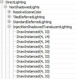
Interestingly, in case the number of non-shadowcasting (and non-static) visible lights in the scene is greater than 80, the renderer switches from classic deferred shading to tiled deferred lighting.
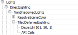
In such a case it uses a compute shader to calculate lighting (for those lights) passing the light data down to the shader through constant buffers (Thanks to wand de for pointing this out). Additionally, the switch to tiled deferred and using a compute shader to apply all lights in one pass appears to affect the direct lighting only. The InjectNonShadowedTranscluscentLighting pass still injects all lights to the translucency lighting volumes individually (a separate drawcall each):
The ShadowedLights pass processes all shadowcasting lights, stationary and movable. By default, Unreal processes each shadowcasting light in 3 stages:

First, it calculates screen space shadows (ShadowProjectionOnOpaque), then it injects the light contribution to the translucency lighting volume (InjectTranslucentVolume) and finally calculates the scene lighting (StandardDeferredLighting).
In the case of a Directional Light only Split0 contains any shadow information, as discussed earlier, for this scene. The result of the shadow calculations are written to a screen-sized RGBA8 buffer.

The next step (InjectTranslucentVolume) writes the directional light’s contribution to the translucency lighting volume we described earlier for both cascades (two drawcalls per InjectTranslucentVolume pass). Finally, the StandardDeferredLighting pass calculates and applies lighting, masked by the screen space shadow buffer, to the SceneColorDeferred buffer.
Local lights seem to follow the same pattern of projecting shadows to a screen space buffer, injecting light into the translucency lighting volumes and calculating lighting into the SceneColorDeferred buffer.

Both types are handled pretty similarly, a difference between movable/stationary local lights is that the movable ones inject shadowed lighting into the translucency lighting volume and, of course, movable shadowed lights use a cubemap instead of the per object atlas for shadowing.
All lights use the same screenspace shadow buffer rendertarget, clearing the relevant parts for each light shadowing, to save some memory I presume.
At the end of the lighting pass, SceneColorDeferred contains all the direct light accumulation for the scene.

It is worth noting that although the renderer has produced a light binning/clustering data structure earlier (Light Assignment pass), it is not being used at all during the solid geometry lighting pass, favouring instead a more traditional deferred shading approach, rendering each light individually.
As a final step the translucency lighting volumes (for both cascades) are filtered to suppress aliasing when lighting translucent props/effects.

In the final blog post we are wrapping up the exploration of Unreal’s renderer with image space lighting, transparency rendering and post processing.
This is part 3 of the “How Unreal Renders a Frame” series, you can access part 1 and part 2 as well.
In this blog post we are wrapping up the exploration of Unreal’s renderer with image space lighting, transparency rendering and post processing.
Image space lighting
Next, screen space reflections are calculated in full screen (RGBA16_FLOAT rendertarget format).

The shader also uses the Hi-Z buffer calculated towards the beginning of the frame to speed up intersection calculations by selecting the Hi-Z mip during raymarching based on the surface roughness (i.e. making raytracing coarser for rougher surfaces where details in the reflection are not visible). Finally every frame the ray start position is jittered, which combined with temporal antialiasing increases the reflections image quality.

The shader uses the previous frame’s rendertarget for sampling colour when a hit is determined during raymarching, you can see this from the volumetric fog in the reflections as well as the reflected transparent props (statues). You can also see hints of the particle effect under the chair on the right. Since we lack proper depth for transparent surfaces (to calculate the correct hits) the reflections are usually stretched but the effect is fairly convincing in many cases.
The screen space reflections are applied to the main rendertarget using a compute shader (ReflectionEnvironment pass). This shader also applies the environmental reflections captured by the two reflection probes in the scene. The reflections are stored in a mipmapped cubemap per probe:

The environment reflection probes are generated during game startup and they only capture “Static” geometry (notice how the animated Rock prop is missing in the above cubemaps).
Our scene, with SSR and environmental reflections applied, now looks like this.

Fog and atmospheric effects
Fog and atmospheric effect follow, again if activated in your scene.

First a quarter resolution lightshaft occlusion mask is created which specifies which pixels will receive a lightshafts (which apply only to the directional light in this scene).

The renderer then goes on to improve the quality of the mask using temporal antialiasing and applies 3 blurring passes to it producing this mask (which I had to enhance at it was mostly white):

It is not entirely clear to me from this GPU capture why temporal AA is applied to the mask before blurring it, as the final result is very low res. It will probably take more use cases in different environments to clarify this.
Before applying the fog and lightshafts to the scene, the renderer takes a quite break to apply atmospherics to the main rendertarget (full res).

This looks like a full-blown scattering calculation, using precomputed transmittance, irradiance and inscattering, similar to Bruneton et al.

This being an indoors scene the effects of the simulation are not very visible unfortunately.
Finally, the renderer applies the exponential fog and lightshafts to the scene.

The shader uses the Volumetric Fog volume texture produced a few passes ago, using the solid geometry position to sample from it. It also applies the lightshaft mask calculated above.
Transparency rendering
After fog has been applied to solid props, the renderer tackles translucent geometry and effects.

In the scene I have added 2 glass statues which get rendered first, using normal alpha blending over the main render target.

The two transparent props sit in the scene very well, being affected by the local and directional lights, environmental reflections, fog etc. By default, the renderer uses a high quality shader to render transparent props which samples, among others, the atmospheric simulation precomputed textures, baked lightmap data, the translucency lighting volumes which contain lighting from the directional and local lights and the reflection probe cubemaps and uses them to calculate lighting. I didn’t see the shader reading the volumetric fog volume texture though, it only seems to calculate height/distance based fog, maybe I missed a setting somewhere. The distance fog, like the atmospheric scattering is calculated in the vertex shader.
Particle effects the renderer writes out to a separate (full resolution) rendertarget.

Like for transparent props, the atmospheric scattering and fog are calculated in the vertex shader. Additionally, based on the particle system settings, the renderer can use the translucency lighting volumes to light the particles (in the pixel shader in the one instance I saw it doing this).
The renderer performs another pass before finishing off the transparencies to calculate refraction.

Both transparent props and particles (that are set to refract) are rendered again to write out a full resolution buffer with the distortion vectors that will later be used to calculate refraction (I enhanced the image to make the vectors more visible). The stencil buffer is also active during that pass to mark the pixels that need refracting.

During the refraction calculation pass (DistortionApply) the renderer reads the contents of the main rendertarget (so far) and the distortion vectors and writes out a weird refraction texture.

Since the stencil buffer is active to mark the pixels that will receive the refraction, the renderer does not need to clear the texture.
The final refraction pass just copies the refraction texture to the main rendertarget, using the stencil as we’ve already mentioned.

You can maybe notice the refraction on the right chair which is due to the particles that we did not apply yet. For the transparent props the refraction is rendered after the prop has been rendered.
The next pass (BokehDOFRecombine), finally applies the particles to the scene. It is a simple shader which does less that the pass name suggests (maybe it depends on the rendering settings).

Post processing
The final part of the frame timeline involves some postprocessing passes which will briefly go through.

With the current scene configuration, the renderer applies temporal antialiasing, motion blur, auto exposure calculations, bloom and tonemapping to the main rendertarget.
Unreal’s temporal antialiasing uses a history buffer to accumulate samples over time and it is rendered in two passes. The first pass implements the temporal AA for pixels that are not stencilled (in this case some particles) using the main rendertarget, the history buffer and the velocity buffer for reprojection:

Then a similar temporal AA pass is performed for the stencilled bits to produce the final antialiased image:

The difference between those two temporal AA passes is that the first one uses a blend factor (feedback) between the history buffer and the current rendertarget that is variable and can depend on pixel luminocity, distance, renderer provided weights etc (based on the settings), the second pass uses a fixed blend factor of 0.25, meaning that the final antialiased pixel will mostly contain the current sample. I assume this is done to reduce ghosting for fast moving particles for which we have no velocity information.
Next Motion Blur follows, preceded by a velocity flattening and dilation pass.

The effect of motion blur in this case is not very noticeable because in the current scene the camera is static and the only moving prop, for which we have velocities, is the Rock (which is already slightly blurred due to motion and temporal antialiasing).
To implement autoexposure (eye adaption) the renderer creates a histogram of the current scene luminocity using a compute shader. The histogram bin pixel intensities and calculates how many pixels fall within each intensity bin.

The advantage of such an approach is that we can easily skip areas of an image that have very dark values or very bright values and produce a more reasonable approximation of the average scene luminance. Using that average luminance the renderer can then calculate the eye adaptation by adjusting the exposure accordingly (bright images will lead to low exposure and darker images will lead to higher exposure).
A series of downscaling passes using Gaussian filtering take place, followed by a series of upscaling and combining to implement the Bloom effect (image adjusted to make it more visible, without exposure control).

The PostProcessCombineLUTs pass uses a geometry shader and a fairly long pixel shader to create the colourgrading LUT (a 32x32x32 RGB10A2 volume texture) that will be used during tonemapping:

The final pass in the frame, Tonemapper, combines the bloom calculated above with the main rendertarget, adjusts the exposure of the image using the eye adaptation calculated previously before passing the colour through the colourgrading LUT to produce the final pixel colour:

Wrapping up
I must stress that this was just one path through the renderer, many parameters and settings might affect it and we have just scratched the surface really.
In overall, that was an interesting exercise, although with the large amount of work done in a frame it turned out more of a “what” the renderer does than “how” than I’d like and I left many things unexplored that I would like to revisit.
Unreal’s renderer source is not extensively documented but it is fairly clean and easy to understand and by following the drawcall list it is easy to find the code that corresponds to it. It can be quite hard to follow what the shaders do in many cases, by studying the source, though as it uses conditional compilation extensively. It would be nice if there was some intermediate cache of processed, “compile-able” shader specialisations (with names injected into the drawcall list) for inspection and performance profiling.
By default, Unreal’s renderer appears to place an emphasis on producing high quality images. It relies on baking of data (environment, light, volumetrics etc) as much as possible and uses temporal antialiasing to a great effect to improve image quality.
It is worth keeping an eye out on the occlusion pass cost if you have lots of props in the scene and not many opportunities for occlusion (i.e. many large occluders). Also refraction on transparent props and particles forces them to render twice. Finally, many stationary or movable local lights may have an impact during the Lighting pass as they are rendered individually (and add to the light injection pass cost for transparencies and volumetrics).
Closing, kudos to Baldurk for the excellent RenderDoc and to Epic for making the source code of Unreal available to all to use, study and learn.