任务要求:
1.根据以下描述功能用verilog编写一段代码,并用状态机来实现该功能。
(1)状态机:实现一个测试过程,该过程包括启动准备状态、启动测试、停止测试、查询测试结果、显示测试结果、测试结束返回初始化6个状态;用时间来控制该过程,90秒内完成该过程;
(2)描述状态跳转时间;
(3)编码实现。
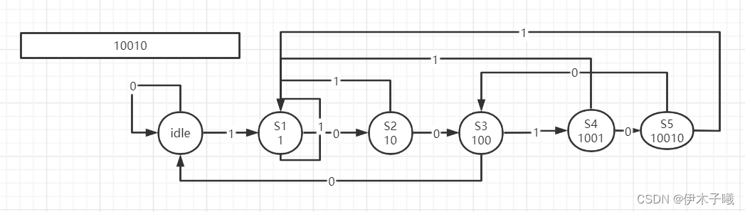
2. 画出可以检测10010串的状态图, 并用verilog编程实现之。
一、状态机的种类
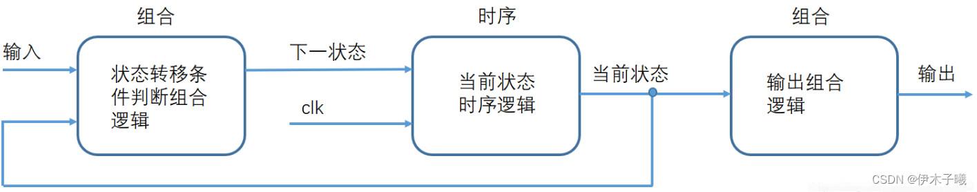
1. Moore型状态机
状态机的输出至于当前的状态有关,如下图所示。
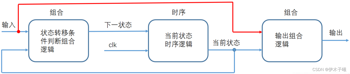
2. Mealy型状态机
状态机的输出不仅与当前的状态有关,还与当前的输入有关,如下图所示。
二、状态机要素
1、FSM要安全,稳定性高(最重要,优先级最高),即FSM不会进入死循环,特别是不会进入非预知的状态,即要求FSM的综合实现结果无毛刺等扰动,要求状态机要完备;
2、FSM速度快,满足设计的频率要求;
3、FSM面积小,满足设计的面积要求;
4、FSM设计要清晰易懂,易维护。
三、任务一
-
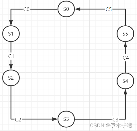
状态流程图
-
说明
| 序号 | 状态 | 说明 |
|---|---|---|
| S0 | 初始化状态(initial) | |
| S1 | 准备状态(ready) | 准备20秒钟 |
| S2 | 启动状态(start) | 经过15秒测试完成 |
| S3 | 停止状态(stop) | 经过10秒测试结束 |
| S4 | 查询状态(search) | 经过30秒测试结果查询 |
| S5 | 结果状态(display) | 显示10s测试结果 |
| 序号 | 时间 | 说明 |
|---|---|---|
| C0 | 1s | 到S1状态,led0亮 |
| C1 | 21s | 进入S2状态,led0,1亮 |
| C2 | 36s | 进入S3状态,led0,1,2 亮 |
| C3 | 46s | 进入S4状态,led0,1,2,3亮 |
| C4 | 76s | 进入S5结果显示状态 ,led0,1,2,3闪烁 |
| C5 | 86s | 返回S0初始化状态,led都灭 |
- 代码实现
module FSM1_1(
	input clk,
	input rst_n,

	output reg [3:0] led

);

parameter CNT_MAX=49_999_999;//1s
parameter LED_MAX=24_999_999;//0.5s
parameter TIMER_MAX=89; // 90s

reg [25:0] cnt;//计数时间,最大为1s
reg [24:0] led_cnt;//计数led闪烁间隔时间
reg [6:0] timer;//时间s为单位
reg [2:0] state;//当前状态

//6种状态
parameter S0=3'd0,
			 S1=3'd1,
			 S2=3'd2,
			 S3=3'd3,
			 S4=3'd4,
			 S5=3'd5;
//时间计数
always@(posedge clk, negedge rst_n)begin
	if(!rst_n)begin
		cnt<=26'd0;
		timer<=7'd0;
	end
	else if(cnt==CNT_MAX)begin
		cnt<=26'd0;
		if(timer==TIMER_MAX)
			timer<=7'd0;
		else
			timer<=timer+7'd1;
	end
	else
		cnt<=cnt+25'd1;
end

//状态转换
always@(posedge clk, negedge rst_n)begin
	if(!rst_n)
		state<=S0;
	else
		case(state)
			S0:begin//inital
					if(timer==1)
						state<=S1;
					else
						state<=S0;
				end
			S1:begin//ready
					if(timer==21)
						state=S2;
					else
						state<=state;
				end
			S2:begin//start
					if(timer==36)
						state<=S3;
					else
						state<=state;
				end
			S3:begin//stop
					if(timer==46)
						state<=S4;
					else
						state<=state;
				end
			S4:begin//search
					if(timer==76)
						state<=S5;
					else
						state<=state;
				end
			S5:begin//display
					if(timer==86)
						state<=S0;
					else
						state<=state;
				end
			default:state<=S0;
		endcase
end


//led时间计数
always@(posedge clk, negedge rst_n)begin
	if(!rst_n)begin
		led_cnt<=25'd0;
	end
	else if(led_cnt==LED_MAX)begin
		led_cnt<=25'd0;
	end
	else
		led_cnt<=led_cnt+25'd1;
end

//led转换
always@(posedge clk, negedge rst_n)begin
	if(!rst_n)
		led<=4'b0000;
	else
		case(state)
			S0:led<=4'b0000;
			S1:led<=4'b0001;
			S2:led<=4'b0011;
			S3:led<=4'b0111;
			S4:led<=4'b1111;
			S5:begin
					if(led_cnt==LED_MAX)
						led<=~led;
					else
						led<=led;
				end
			default:led<=4'b0000;
		endcase
end
endmodule
四、任务二
-
状态流程图
-
代码实现
module str_detector (
		input		 rst_n,
		input		 clk,
		input	    str,//输入

		output reg str_check //输出匹配结果
);


reg   [2:0]   curr_state ;
reg   [2:0]   Next_state ;

  parameter	str_idle  = 3'd0,					//起始
         	str_S1    = 3'd1,					//1
  		      str_S2    = 3'd2,					//10
  		      str_S3    = 3'd3,					//100
  		      str_S4    = 3'd4,					//1001
            str_S5    = 3'd5;                   //10010

always @(posedge clk or negedge rst_n)
 begin
   if (!rst_n)
     curr_state <= str_idle;
   else
     curr_state <= Next_state;
 end

always @(*)
begin
  case(curr_state)
   str_idle:
     if (str==1)
       Next_state = str_S1;
     else
       Next_state = str_idle;
   str_S1:
     if (str==0)
       Next_state = str_S2;
     else
       Next_state = str_S1;
   str_S2:
     if (str==0)
       Next_state = str_S3;
     else
       Next_state = str_S1;
   str_S3:
     if (str==1)
       Next_state = str_S4;
     else
       Next_state = str_idle;
   str_S4:
     if (str==1)
       Next_state = str_S1;
     else
       Next_state = str_S5;
   str_S5:
     if (str==1)
       Next_state = str_S1;
     else
       Next_state = str_S3;
   default:
       Next_state = str_idle;
  endcase
end


always @(posedge clk or negedge rst_n)
begin
    if(!rst_n)
	  str_check <= 1'b0;
	else if(curr_state==str_S5)
	  str_check <= 1'b1;
	else
	  str_check <= 1'b0;
end

endmodule
五、总结
通过本次实验,更加深入的理解了状态机的实现原理,同时也熟悉了通过verilog编写状态机的代码实现流程。