实验题目及要求:
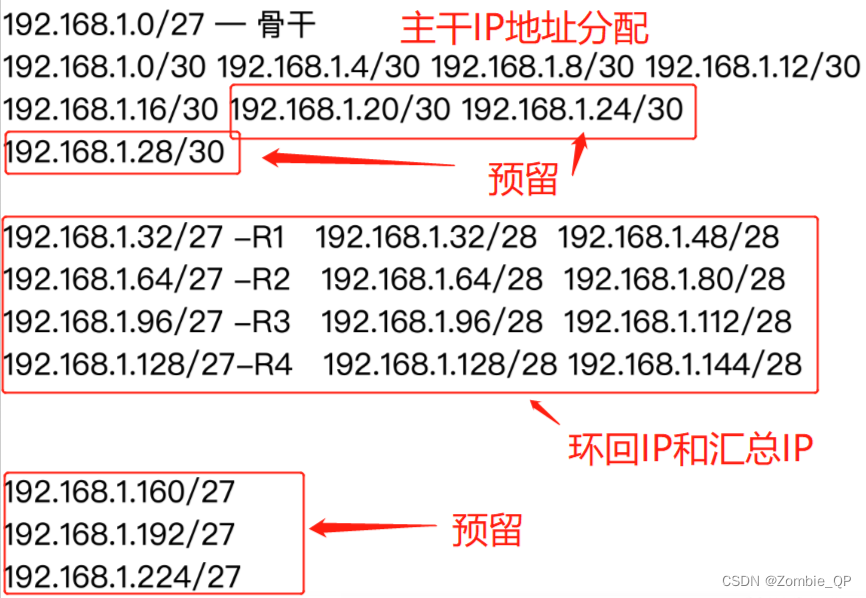
1、分析IP地址分配。
主干IP掩码均为30;
环回IP掩码为28,方便汇总掩码27;
然后预留部分IP地址。
如下图:
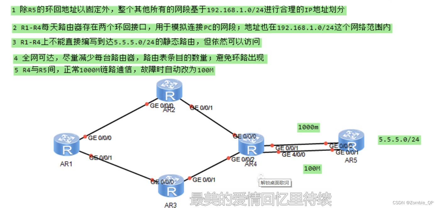
2、按如上图片要求连接设备,并标记好IP分配信息,便于命令配置时一目了然。

3、进入各路由器VRP界面开始命令配置,配置IP地址命令如下(含解析):
R1:
<Huawei>sys			//进入第二层
Enter system view, return user view with Ctrl+Z.
[Huawei]sysname r1 			//将路由器改名为r1
[r1]int g 0/0/0			//进入接口,按之前信息标注开始配置IP地址
[r1-GigabitEthernet0/0/0]ip add 192.168.1.21 30
Jul 21 2023 10:14:33-08:00 r1 %%01IFNET/4/LINK_STATE(l)[0]:The line protocol IP
on the interface GigabitEthernet0/0/0 has entered the UP state.
[r1-GigabitEthernet0/0/0]q
[r1]int g 0/0/1
[r1-GigabitEthernet0/0/1]ip add 192.168.1.17 30
Jul 21 2023 10:15:20-08:00 r1 %%01IFNET/4/LINK_STATE(l)[1]:The line protocol IP
on the interface GigabitEthernet0/0/1 has entered the UP state.
[r1-GigabitEthernet0/0/1]q
[r1]int LoopBack 0			//进入环回接口
[r1-LoopBack0]ip add 192.168.1.145 28				//给环回接口配置IP地址,将环回接口模拟成一台pc
[r1-LoopBack0]q
[r1]int loopb 1
[r1-LoopBack1]ip add 192.168.1.129 28
[r1-LoopBack1]q
R2:
<Huawei>sys
Enter system view, return user view with Ctrl+Z.
[Huawei]sysname r2
[r2]int g 0/0/0
[r2-GigabitEthernet0/0/0]ip add 192.168.1.22 30
Jul 21 2023 10:19:12-08:00 r2 %%01IFNET/4/LINK_STATE(l)[0]:The line protocol IP
on the interface GigabitEthernet0/0/0 has entered the UP state.
[r2-GigabitEthernet0/0/0]q
[r2]int g 0/0/1
[r2-GigabitEthernet0/0/1]ip add 192.168.1.9 30
Jul 21 2023 10:19:34-08:00 r2 %%01IFNET/4/LINK_STATE(l)[1]:The line protocol IP
on the interface GigabitEthernet0/0/1 has entered the UP state.
[r2-GigabitEthernet0/0/1]q
[r2]int loopb 0
[r2-LoopBack0]ip add 192.168.1.81 28
[r2-LoopBack0]q
[r2]int loopb 1
[r2-LoopBack1]ip add 192.168.1.165 28
[r2-LoopBack1]q
R3:
<Huawei>sys
Enter system view, return user view with Ctrl+Z.
[Huawei]sysname r3
[r3]int g 0/0/0
[r3-GigabitEthernet0/0/0]ip add 192.168.1.18 30
Jul 21 2023 10:21:58-08:00 r3 %%01IFNET/4/LINK_STATE(l)[0]:The line protocol IP
on the interface GigabitEthernet0/0/0 has entered the UP state.
[r3-GigabitEthernet0/0/0]q
[r3]int g 0/0/1
[r3-GigabitEthernet0/0/1]ip add 192.168.1.13 30
Jul 21 2023 10:22:24-08:00 r3 %%01IFNET/4/LINK_STATE(l)[1]:The line protocol IP
on the interface GigabitEthernet0/0/1 has entered the UP state.
[r3-GigabitEthernet0/0/1]q
[r3]int loopb 0
[r3-LoopBack0]ip add 192.168.1.97 28
[r3-LoopBack0]q
[r3]int loopb 1
[r3-LoopBack1]ip add 192.168.1.113 28
R4:
<Huawei>sys
Enter system view, return user view with Ctrl+Z.
[Huawei]sysname r4
[r4]int g 0/0/0
[r4-GigabitEthernet0/0/0]ip add 192.168.1.14 30
Jul 21 2023 10:26:37-08:00 r4 %%01IFNET/4/LINK_STATE(l)[0]:The line protocol IP
on the interface GigabitEthernet0/0/0 has entered the UP state.
[r4-GigabitEthernet0/0/0]q
[r4]int g 0/0/1
[r4-GigabitEthernet0/0/1]ip add 192.168.1.10 30
Jul 21 2023 10:26:59-08:00 r4 %%01IFNET/4/LINK_STATE(l)[1]:The line protocol IP
on the interface GigabitEthernet0/0/1 has entered the UP state.
[r4-GigabitEthernet0/0/1]q
[r4]int g 0/0/2
[r4-GigabitEthernet0/0/2]ip add 192.168.1.2 30
Jul 21 2023 10:27:23-08:00 r4 %%01IFNET/4/LINK_STATE(l)[2]:The line protocol IP
on the interface GigabitEthernet0/0/2 has entered the UP state.
[r4-GigabitEthernet0/0/2]q
[r4]int g 4/0/0
[r4-GigabitEthernet4/0/0]ip add 192.168.1.5 30
Jul 21 2023 10:27:48-08:00 r4 %%01IFNET/4/LINK_STATE(l)[3]:The line protocol IP
on the interface GigabitEthernet4/0/0 has entered the UP state.
[r4-GigabitEthernet4/0/0]q
[r4]int loopb 0
[r4-LoopBack0]ip add 192.168.1.33 28
[r4-LoopBack0]q
[r4]int loopb 1
[r4-LoopBack1]ip add 192.168.1.49 28
[r4-LoopBack1]
R5:
<Huawei>sys
Enter system view, return user view with Ctrl+Z.
[Huawei]sysname r5
[r5]int g 0/0/0
[r5-GigabitEthernet0/0/0]ip add 192.168.1.1 30 			//模拟为1000兆接口
Jul 21 2023 10:29:53-08:00 r5 %%01IFNET/4/LINK_STATE(l)[0]:The line protocol IP
on the interface GigabitEthernet0/0/0 has entered the UP state.
[r5-GigabitEthernet0/0/0]q
[r5]int g 0/0/1
[r5-GigabitEthernet0/0/1]ip add 192.168.1.6 30				//模拟为100兆接口
Jul 21 2023 10:30:19-08:00 r5 %%01IFNET/4/LINK_STATE(l)[1]:The line protocol IP
on the interface GigabitEthernet0/0/1 has entered the UP state.
[r5-GigabitEthernet0/0/1]q
[r5]int loopb0
[r5-LoopBack0]ip add 5.5.5.5 24
4、给各路由配空接口防环路由、缺省路由,同时配置静态路由。
R1:
<r1>sys
Enter system view, return user view with Ctrl+Z.
[r1]ip route-static 192.168.1.128 27 null 0				//空接口防环路由
[r1]ip route-static 0.0.0.0 0.0.0.0 192.168.1.22			//配置缺省路由
[r1]ip route-static 0.0.0.0 0.0.0.0 192.168.1.18
[r1]ip route- 192.168.1.8 30 192.168.1.22				//配置静态路由
[r1]ip route- 192.168.1.12 30 192.168.1.18
[r1]ip route- 192.168.1.0 30 191.168.1.20
[r1]ip route- 192.168.1.4 30 191.168.1.20
[r1]ip route- 192.168.1.0 30 191.168.1.16
[r1]ip route- 192.168.1.4 30 191.168.1.16
R2:
扫描二维码关注公众号,回复:
15860546 查看本文章

<r2>sys
Enter system view, return user view with Ctrl+Z.
[r2]ip route-static 192.168.1.64 27 null 0
[r2]ip route-static 0.0.0.0 0.0.0.0 192.168.1.10
[r2]ip route-static 192.168.1.128 27 192.168.1.21
[r2]ip route- 192.168.1.0 30 192.168.1.10
[r2]ip route- 192.168.1.4 30 192.168.1.10
[r2]ip route- 192.168.1.12 30 192.168.1.1
[r2]ip route- 192.168.1.96 27 192.168.1.10
[r2]ip route- 192.168.1.96 27 192.168.1.21
[r2]ip route- 192.168.1.16 30 192.168.1.21
[r2]ip route- 192.168.1.32 27 192.168.1.10
R3:
<r3>sys
Enter system view, return user view with Ctrl+Z.
[r3]ip route-static 192.168.1.96 27 null 0
[r3]ip route-static 0.0.0.0 0.0.0.0 192.168.1.14
[r3]ip route-static 192.168.1.128 27 192.168.1.17
[r3]ip route- 192.168.1.0 30 192.168.1.14
[r3]ip route- 192.168.1.4 30 192.168.1.14
[r3]ip route- 192.168.1.8 30 192.168.1.14
[r3]ip route- 192.168.1.32 27 192.168.1.14
[r3]ip route- 192.168.1.64 27 192.168.1.17
[r3]ip route- 192.168.1.20 30 192.168.1.17
[r3]ip route- 192.168.1.64 27 192.168.1.14
R4:
<r4>sys
Enter system view, return user view with Ctrl+Z.
[r4]ip route-static 192.168.1.32 27 null 0
[r4]ip route-static 0.0.0.0 0.0.0.0 192.168.1.1
[r4]ip route-static 0.0.0.0 0.0.0.0 192.168.1.6 preference 61
[r4]ip route-static 192.168.1.64 27 192.168.1.9
[r4]ip route-static 192.168.1.96 27 192.168.1.13
[r4]ip route-static 192.168.1.128 27 192.168.1.13
[r4]ip route-static 192.168.1.128 27 192.168.1.9
[r4]ip route- 192.168.1.20 30 192.168.1.9
[r4]ip route- 192.168.1.16 30 192.168.1.13
R5:
[r5]ip route-static 192.168.1.32 27 192.168.1.2
[r5]ip route-static 192.168.1.64 27 192.168.1.2
[r5]ip route-static 192.168.1.128 27 192.168.1.2
[r5]ip route-static 192.168.1.8 30 192.168.1.2
[r5]ip route-static 192.168.1.20 30 192.168.1.2
[r5]ip route-static 192.168.1.12 30 192.168.1.2
[r5]ip route-static 192.168.1.16 30 192.168.1.2
[r5]ip route-static 192.168.1.96 27 192.168.1.2
[r5]ip route-static 192.168.1.128 27 192.168.1.5 preference 61
[r5]ip route-static 192.168.1.96 27 192.168.1.5 preference 61
[r5]ip route-static 192.168.1.16 30 192.168.1.5 preference 61
[r5]ip route-static 192.168.1.12 30 192.168.1.5 preference 61
[r5]ip route-static 192.168.1.8 30 192.168.1.5  preference 61
[r5]ip route-static 192.168.1.20 30 192.168.1.5 preference 61
[r5]ip route-static 192.168.1.64 27 192.168.1.5  preference 61
[r5]ip route-static 192.168.1.32 27 192.168.1.5 preference 61
以上操作基本就把该实验完成了,最后验证就需要断开R4的0/0/2口进行测试、然后利用R1来ping
< r1>ping 5.5.5.5
PING 5.5.5.5: 56 data bytes, press CTRL_C to break
Request time out
Reply from 5.5.5.5: bytes=56 Sequence=2 ttl=253 time=50 ms
Reply from 5.5.5.5: bytes=56 Sequence=3 ttl=253 time=50 ms
Reply from 5.5.5.5: bytes=56 Sequence=4 ttl=253 time=30 ms
Reply from 5.5.5.5: bytes=56 Sequence=5 ttl=253 time=30 ms
— 5.5.5.5 ping statistics —
5 packet(s) transmitted
4 packet(s) received
20.00% packet loss
round-trip min/avg/max = 30/40/50 ms