目录
模型文件下载
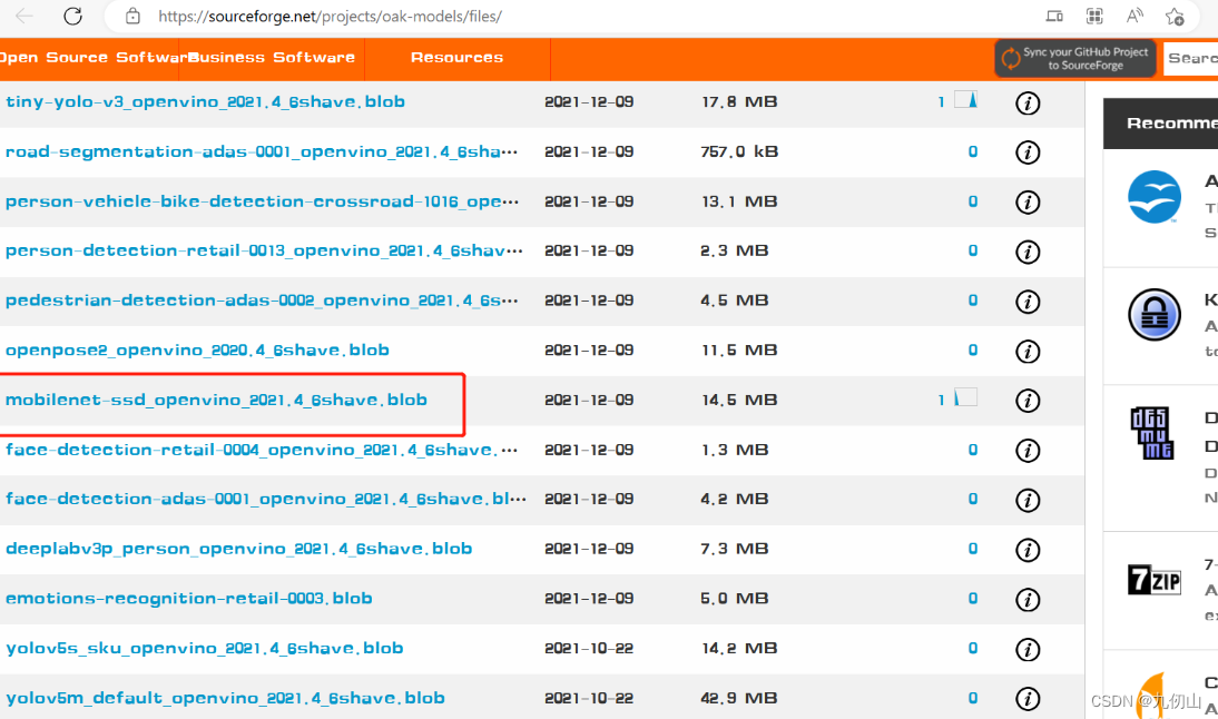
这里用到了mobilenet-ssd_openvino_2021.4_6shave.blob模型文件,mobilenet-ssd_openvino_2021.4_6shave.blob 是一个已经训练好的模型文件,用于目标检测任务。该模型一共可以检测21种目标类型。包括:“background”, “aeroplane”, “bicycle”, “bird”, “boat”, “bottle”, “bus”, “car”, “cat”, “chair”, “cow”, “diningtable”, “dog”, “horse”, “motorbike”, “person”, “pottedplant”, “sheep”, “sofa”, “train”, “tvmonitor”。
可以从这个网站下载该文件:oak_models - Browse Files at SourceForge.net
在项目根目录下新建models文件夹,将上面下载的文件拷贝到models文件夹
代码实现
Setup 1: 创建文件
- 创建新建12-mono-mobilenetSSD-depth文件夹
- 用vscode打开该文件夹
- 新建一个main.py 文件
Setup 2: 安装依赖
安装依赖前需要先创建和激活虚拟环境,我这里已经创建了虚拟环境OAKenv,在终端中输入cd…退回到OAKenv的根目录,输入 OAKenv\Scripts\activate激活虚拟环境
安装pip依赖项:
pip install numpy opencv-python depthai blobconverter --user
Setup 3: 导入需要的包
在main.py中导入项目需要的包
from pathlib import Path
import sys
import cv2
import depthai as dai
import numpy as np
pathlib用于处理文件路径,sys用于系统相关的操作,cv2是OpenCV库用于图像处理,depthai是depthai库用于深度计算和AI推理。
Setup 4:定义和加载模型相关的路径和标签
nnPath = str((Path(__file__).parent / Path('../models/mobilenet-ssd_openvino_2021.4_6shave.blob')).resolve().absolute())
if len(sys.argv) > 1:
    nnPath = sys.argv[1]

if not Path(nnPath).exists():
    import sys
    raise FileNotFoundError(f'Required file/s not found, please run "{sys.executable} install_requirements.py"')

labelMap = ["background", "aeroplane", "bicycle", "bird", "boat", "bottle", "bus", "car", "cat", "chair", "cow","diningtable", "dog", "horse", "motorbike", "person","pottedplant", "sheep", "sofa", "train", "tvmonitor"]
-
使用
Path(__file__).parent获取当前脚本的父目录,然后使用Path('../models/mobilenet-ssd_openvino_2021.4_6shave.blob')拼接上模型文件的相对路径,再使用resolve().absolute()将相对路径解析为绝对路径,并将结果转换为字符串类型。最终,得到了模型文件的完整路径并赋值给变量nnPath。 -
检查命令行参数(
sys.argv)的数量,如果大于1(即有额外的命令行参数)则将第一个参数赋值给nnPath。这样可以在运行代码时通过命令行参数指定模型文件的路径。 -
使用
Path(nnPath).exists()检查模型文件是否存在,如果不存在则引发FileNotFoundError异常,同时提供错误消息指示缺少的文件。 -
定义一个标签列表
labelMap,其中包含了模型预测的类别名称。共包含了21个类别
Setup 5: 创建pipeline
pipeline = dai.Pipeline()
Setup 6: 创建节点
monoRight = pipeline.createMonoCamera()
monoLeft = pipeline.createMonoCamera()
stereo = pipeline.createStereoDepth()
manip = pipeline.createImageManip()
nn = pipeline.createMobileNetDetectionNetwork()

nnOut = pipeline.createXLinkOut()
disparityOut = pipeline.createXLinkOut()
xoutRight = pipeline.createXLinkOut()

disparityOut.setStreamName("disparity")
xoutRight.setStreamName("rectifiedRight")
nnOut.setStreamName("nn")
创建节点用于构建pipeline。
monoRight = pipeline.createMonoCamera(): 创建了一个MonoCamera节点,用于接收右侧摄像头的输入图像。
monoLeft = pipeline.createMonoCamera(): 创建了一个MonoCamera节点,用于接收左侧摄像头的输入图像。
stereo = pipeline.createStereoDepth(): 创建了一个StereoDepth节点,用于计算深度图。
manip = pipeline.createImageManip(): 创建了一个ImageManip节点,用于图像处理,例如调整图像的亮度、对比度等。
nn = pipeline.createMobileNetDetectionNetwork(): 创建了一个MobileNetDetectionNetwork节点,用于进行物体检测和分类的推理。
nnOut = pipeline.createXLinkOut(): 创建了一个XLinkOut节点,用于输出神经网络的结果。
disparityOut = pipeline.createXLinkOut(): 创建了一个XLinkOut节点,用于输出深度图。
xoutRight = pipeline.createXLinkOut(): 创建了一个XLinkOut节点,用于输出右侧摄像头的图像。
Setup 7: 设置属性
配置摄像头节点的参数
monoRight.setBoardSocket(dai.CameraBoardSocket.RIGHT)
monoRight.setResolution(dai.MonoCameraProperties.SensorResolution.THE_400_P)
monoLeft.setBoardSocket(dai.CameraBoardSocket.LEFT)
monoLeft.setResolution(dai.MonoCameraProperties.SensorResolution.THE_400_P)
-
monoRight.setBoardSocket(dai.CameraBoardSocket.RIGHT): 将右侧摄像头节点设置为右相机板插槽。 -
monoRight.setResolution(dai.MonoCameraProperties.SensorResolution.THE_400_P): 将右侧摄像头的分辨率设置为400p。 -
monoLeft.setBoardSocket(dai.CameraBoardSocket.LEFT): 将左侧摄像头节点设置为左相机板插槽。 -
monoLeft.setResolution(dai.MonoCameraProperties.SensorResolution.THE_400_P): 将左侧摄像头的分辨率设置为400p。
配置深度图节点的参数
stereo.setDefaultProfilePreset(dai.node.StereoDepth.PresetMode.HIGH_DENSITY)
stereo.setRectifyEdgeFillColor(0)
-
stereo.setDefaultProfilePreset(dai.node.StereoDepth.PresetMode.HIGH_DENSITY): 将深度图节点设置为高密度预设模式,该模式可以提供更丰富的深度信息。 -
stereo.setRectifyEdgeFillColor(0): 将矫正边缘的填充颜色设置为0。矫正边缘是指通过对图像进行几何校正来消除镜头畸变,填充颜色为0表示使用黑色填充。
配置图像处理节点的参数
manip.initialConfig.setResize(300, 300)
manip.initialConfig.setFrameType(dai.ImgFrame.Type.BGR888p)
-
manip.initialConfig.setResize(300, 300): 将图像处理节点的输入尺寸设置为300x300。这意味着输入图像将被调整为300x300的大小。 -
manip.initialConfig.setFrameType(dai.ImgFrame.Type.BGR888p): 设置图像处理节点的输出图像类型为BGR888p,也就是BGR格式的图像。默认情况下,ImageManip节点的输出类型与输入类型相同(在这种情况下是灰度图像),但是通过设置输出类型为BGR888p,可以将其转换为BGR格式的图像。
配置神经网络节点的参数
nn.setConfidenceThreshold(0.5)
nn.setBlobPath(nnPath)
nn.setNumInferenceThreads(2)
nn.input.setBlocking(False)
-
nn.setConfidenceThreshold(0.5): 将神经网络节点的置信度阈值设置为0.5。这意味着神经网络模型输出的结果中,只有大于0.5的置信度才会被认为是有效的预测结果。 -
nn.setBlobPath(nnPath): 设置神经网络节点使用的模型文件路径。nnPath参数应该是一个包含了神经网络模型的二进制文件的路径。 -
nn.setNumInferenceThreads(2): 设置神经网络节点的推理线程数为2。通过多线程推理,可以加快神经网络模型的处理速度。 -
nn.input.setBlocking(False): 设置神经网络节点的输入为非阻塞模式。这意味着在处理神经网络输入时,节点将不会阻塞其他部分的代码执行,从而实现较高的并发性。
Setup 8: 建立链接
monoRight.out.link(stereo.right)
monoLeft.out.link(stereo.left)
stereo.rectifiedRight.link(manip.inputImage)
stereo.disparity.link(disparityOut.input)
manip.out.link(nn.input)
manip.out.link(xoutRight.input)
nn.out.link(nnOut.input)
连接不同的节点以建立数据流。
-
monoRight.out.link(stereo.right): 将monoRight节点的输出连接到stereo节点的右侧输入。提供右侧相机的视频流作为stereo节点的输入。 -
monoLeft.out.link(stereo.left): 将monoLeft节点的输出连接到stereo节点的左侧输入。提供左侧相机的视频流作为stereo节点的输入。 -
stereo.rectifiedRight.link(manip.inputImage): 将stereo节点处理后的右侧图像连接到manip节点的输入。把经过立体视觉校正的右侧图像作为manip节点的输入。 -
stereo.disparity.link(disparityOut.input): 将stereo节点的视差图连接到disparityOut节点的输入。提供立体匹配后的视差图作为disparityOut节点的输入。 -
manip.out.link(nn.input): 将manip节点的输出连接到nn节点的输入。提供预处理后的图像作为nn节点的输入。 -
manip.out.link(xoutRight.input): 将manip节点的输出连接到xoutRight节点的输入。提供预处理后的图像作为右侧输出的输入。 -
nn.out.link(nnOut.input): 将nn节点的输出连接到nnOut节点的输入。将神经网络的输出连接到后续的处理或输出节点。
Setup 9: 连接设备并启动管道
with dai.Device(pipeline) as device:
Setup 10: 创建与DepthAI设备通信的输出队列
    qRight = device.getOutputQueue("rectifiedRight", maxSize=4, blocking=False)
    qDisparity = device.getOutputQueue("disparity", maxSize=4, blocking=False)
    qDet = device.getOutputQueue("nn", maxSize=4, blocking=False)
创建输出队列,以便从设备获取处理后的结果。
-
qRight = device.getOutputQueue("rectifiedRight", maxSize=4, blocking=False): 创建一个名为"rectifiedRight"的输出队列qRight,用于从设备获取立体校正后的右侧图像。maxSize=4表示该队列最多可以存储4个图像结果。blocking=False表示当队列已满时不会阻塞代码的执行。 -
qDisparity = device.getOutputQueue("disparity", maxSize=4, blocking=False): 创建一个名为"disparity"的输出队列qDisparity,用于从设备获取立体匹配后的视差图。maxSize=4表示该队列最多可以存储4个图像结果。blocking=False表示当队列已满时不会阻塞代码的执行。 -
qDet = device.getOutputQueue("nn", maxSize=4, blocking=False): 创建一个名为"nn"的输出队列qDet,用于从设备获取神经网络处理后的结果。maxSize=4表示该队列最多可以存储4个结果。blocking=False表示当队列已满时不会阻塞代码的执行。
Setup11: 定义处理函数
    rightFrame = None
    disparityFrame = None
    detections = []

    def frameNorm(frame, bbox):
        normVals = np.full(len(bbox), frame.shape[0])
        normVals[::2] = frame.shape[1]
        return (np.clip(np.array(bbox), 0, 1) * normVals).astype(int)
frameNorm(frame, bbox):frameNorm函数用于将给定的边界框位置归一化到指定帧的宽度和高度范围内。函数的参数包括一个帧图像(frame)和一个边界框(bbox),返回归一化后的边界框位置。具体操作是将边界框内的数值乘以帧图像的宽度和高度,将其转换为像素坐标,并使用astype(int)将结果转换为整数类型。
    def show(name, frame):
        color = (255, 0, 0)
        for detection in detections:
            bbox = frameNorm(frame, (detection.xmin, detection.ymin, detection.xmax, detection.ymax))
            cv2.putText(frame, labelMap[detection.label], (bbox[0] + 10, bbox[1] + 20), cv2.FONT_HERSHEY_TRIPLEX, 0.5, color)
            cv2.putText(frame, f"{int(detection.confidence * 100)}%", (bbox[0] + 10, bbox[1] + 40), cv2.FONT_HERSHEY_TRIPLEX, 0.5, color)
            cv2.rectangle(frame, (bbox[0], bbox[1]), (bbox[2], bbox[3]), color, 2)

        cv2.imshow(name, frame)

    disparityMultiplier = 255 / stereo.initialConfig.getMaxDisparity()
定义一个show的函数和一个disparityMultiplier的变量。
-
show(name, frame):show函数用于在窗口中展示图像。函数的参数包括展示窗口的名称(name)和要展示的图像(frame)。函数首先使用蓝色(255, 0, 0)来标记检测到的边界框的颜色。然后,遍历detections列表中的每一个检测结果,通过调用frameNorm函数将其边界框的位置归一化到当前帧图像的大小上,并使用cv2.putText函数和cv2.rectangle函数将边界框和标签添加到帧图像上。最后,使用cv2.imshow函数展示帧图像。 -
disparityMultiplier = 255 / stereo.initialConfig.getMaxDisparity():disparityMultiplier是一个用于将视差值映射到灰度图像的亮度值范围的变量。通过将255与stereo.initialConfig.getMaxDisparity()相除,可以得到一个比例因子,用于将视差值归一化到0-255的范围内。
Setup 12: 主循环
while True:
获取图像数据和检测结果并展示。
if qDet.has():
detections = qDet.get().detections
if qRight.has():
rightFrame = qRight.get().getCvFrame()
if qDisparity.has():
disparityFrame = qDisparity.get().getFrame()
disparityFrame = (disparityFrame*disparityMultiplier).astype(np.uint8)
disparityFrame = cv2.applyColorMap(disparityFrame, cv2.COLORMAP_JET)
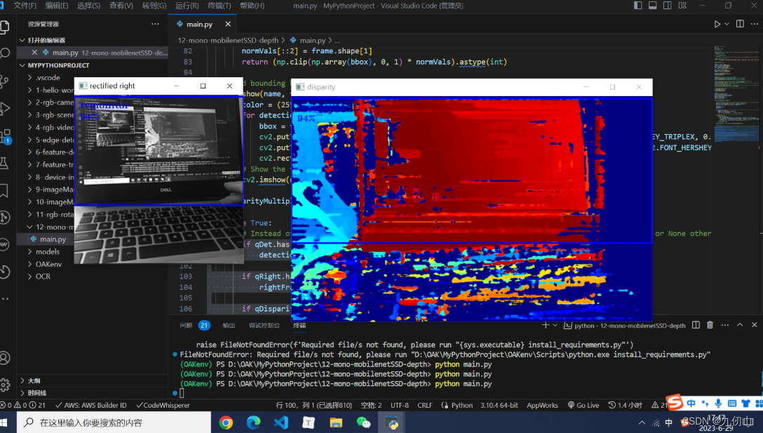
show("disparity", disparityFrame)
if rightFrame is not None:
show("rectified right", rightFrame)
if cv2.waitKey(1) == ord('q'):
break
-
检查队列
qDet是否有新的检测结果。如果有,它从队列中获取最新的结果,并将其中的检测列表赋值给detections变量。 -
检查队列
qRight是否有新的右侧图像数据。如果有,它从队列中获取最新的数据,并将其存储在rightFrame变量中。 -
检查队列
qDisparity是否有新的视差图像数据。如果有,它从队列中获取最新的数据,并进行一系列处理。首先,将视差数据乘以disparityMultiplier,将其归一化到0-255的范围内,并将其转换为无符号8位整数类型。然后,使用OpenCV的cv2.applyColorMap函数将灰度图像转换为伪彩色图像,并应用颜色映射(使用cv2.COLORMAP_JET)。最后,调用show函数将视差图像展示在名为"disparity"的窗口中。 -
检查
rightFrame是否为None。如果不是,它调用show函数将右侧图像展示在名为"rectified right"的窗口中。 -
通过调用
cv2.waitKey(1)等待用户按下键盘上的某个键。如果按下的是键盘上的字母"q"(ord(‘q’)为键盘上字母"q"的ASCII码),则退出主循环,程序终止。
Setup 13:运行程序
在终端中输入如下指令运行程序
python main.py