基于nb-iot和arduino的气象站(一)温湿度和紫外线传感器
使用arduino、nb-iot、温湿度传感器、紫外线传感器、pm2.5传感器、gps传感器,搭建一个移动气象站,该气象站可以实时监测环境状态,通过nb模组上传到服务器,并将数据显示于网页。
这一小系列先分别记录单个模块的使用,然后再将所有的模块合并起来。
这一篇先讲温湿度传感器和紫外线传感器的使用。
一、温湿度传感器
我使用的温度传感器为DHT21。
DHT21数字温湿度传感器是一款含有已校准数字信号输出的温湿度复合传感器。它应用专用的数字模块采集技术和温湿度传感技术,确保产品具有极高的可靠性与卓越的长期稳定性。
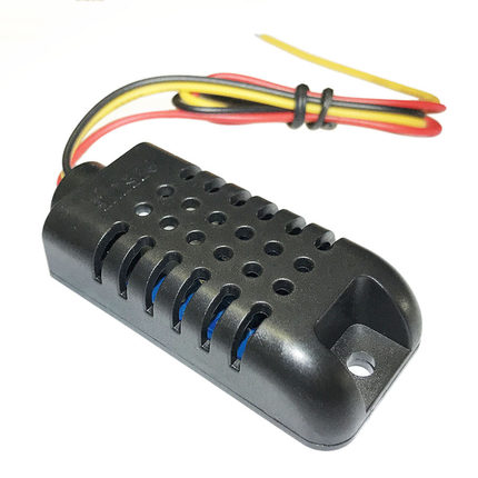
1.1DHT21模块接线说明:
- VCC 外接3.3V-5V
- GND 外接GND
- DATA 串行数据,单总线
1.2DHT21发送数据格式:
通过串口显示温度和湿度值波特率:9600
采用单总线数据格式,一次通讯时间5ms左右 ,具体格式在下面说明,当前数据传输为40bit,高位先出。
例子:0000 0010 1000 1100 0000 0001 0101 1111 1110 1110
其中前16位为湿度数据,接着16位为温度数据,最后8位为校验位。
- 湿度=(高8位*256+低八位)/10
- 温度=((高八位&0x7F)*256+低八位)/10
- 校验位=温度高八位+温度低八位+湿度高八位+湿度低八位
当温度低于0℃时温度数据最高位置为1。
DHT22与此相同,DHT11数据格式略有不同,具体需要看传感器说明书。但是其实arduino已经有了相应的库,并不需要我们自己去处理这些传感器的数据。
1.3参考代码
// 导入头文件
#include "DHT.h"
// 定义OUT接口的数字引脚,即把OUT接口接到arduino的pin2
#define DHTPIN 2

// 选择DHT类型为 DHT 21
//#define DHTTYPE DHT11   // DHT 11
//#define DHTTYPE DHT22   // DHT 22  (AM2302), AM2321
#define DHTTYPE DHT21   // DHT 21 (AM2301)

// 生成 DHT 对象,参数是PIN和DHT类型
DHT dht(DHTPIN, DHTTYPE);

void setup() {
  Serial.begin(9600);
  Serial.println("DHTxx test!");

  // 必须使用的begin()函数
  dht.begin();
}

void loop() {
  // 每次等待2秒后再输出(这里必须等大于1秒,不然不准确)
  delay(2000);

  // readHumidity() 这里是读取当前的湿度
  float h = dht.readHumidity();
  // readTemperature() 读取当前的温度,单位C
  float t = dht.readTemperature();
  //readTemperature(true) 读取当前的温度,单位F
  float f = dht.readTemperature(true);
  // 如果读取失败则退出,再读取一次
  if (isnan(h) || isnan(t) || isnan(f)) {
    Serial.println("Failed to read from DHT sensor!");
    return;
  }

  // 读取体感温度,单位F
  float hif = dht.computeHeatIndex(f, h);
  // 读取体感温度,单位C
  float hic = dht.computeHeatIndex(t, h, false);

  Serial.print("Humidity: ");
  Serial.print(h);
  Serial.print(" %\t");
  Serial.print("Temperature: ");
  Serial.print(t);
  Serial.print(" *C ");
  Serial.print(f);
  Serial.print(" *F\t");
  Serial.print("Heat index: ");
  Serial.print(hic);
  Serial.print(" *C ");
  Serial.print(hif);
  Serial.println(" *F");
}
需要下载DHT库文件,打开arduino后,项目->加载库->管理库,搜索DHT,选择第一个DHT_sensor_library。安装完成后,在arduino的安装目录下library文件夹中会出现对应的库。运行其中的DHTTester,可能会有一个错误,这个错误是缺少 Adafruit_Sensor.h 。可在 https://github.com/adafruit/Adafruit_Sensor 此处下载,将下载后的压缩包解压后,放入library文件夹下。重新打开 Arduino后,编译就没有错误了。
上传之后可以看到 湿度,C温度,F温度,体感C温度,体感F温度。如果不是DHT21,只要将代码中的DHTTYPE作相应修改即可。
二、紫外线传感器
我选择的紫外线传感器型号为ML8511。
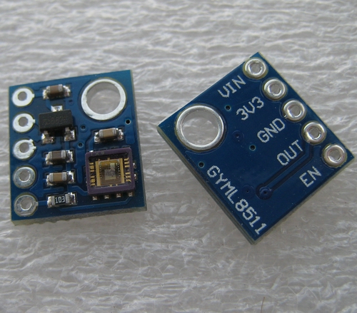
2.1接线说明
- 3V3 外接3.3V
- GND 外接GND
- OUT为数据输出,我将它接了arduinoA0口
- EN接3.3v
2.2输出数据说明
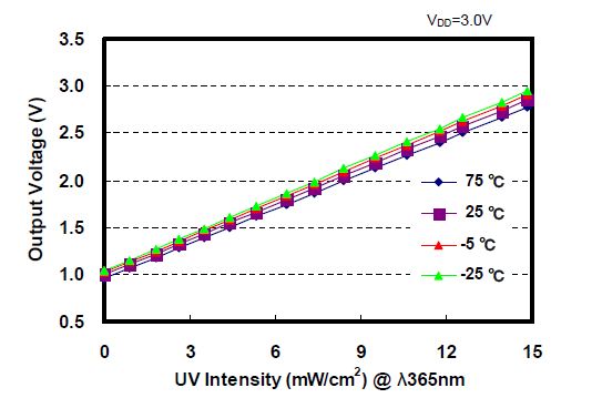
传感器OUT口输出为模拟信号,输出电压值与紫外线强度对应关系如上图所示。
2.3参考代码
/*
 The MP8511 UV Sensor outputs an analog signal in relation to the amount of UV light it detects.

 Connect the following MP8511 breakout board to Arduino:
 3.3V = 3.3V
 OUT = A0
 GND = GND
 EN = 3.3V
 3.3V = A1
 These last two connections are a little different. Connect the EN pin on the breakout to 3.3V on the breakout.
 This will enable the output. Also connect the 3.3V pin of the breakout to Arduino pin 1.

 This example uses a neat trick. Analog to digital conversions rely completely on VCC. We assume this is 5V but if the board is powered from USB this may be as high as 5.25V or as low as 4.75V: http://en.wikipedia.org/wiki/USB#Power Because of this unknown window it makes the ADC fairly inaccurate in most cases. To fix this, we use the very accurate onboard 3.3V reference (accurate within 1%). So by doing an  ADC on the 3.3V pin (A1) and then comparing this against the reading from the sensor we can extrapolate a true-to-life reading no matter what VIN is (as long as it's above 3.4V).
*/

int UVOUT = A0; //Output from the sensor
int REF_3V3 = A1; //3.3V power on the Arduino board

void setup()
{
  Serial.begin(9600);

  pinMode(UVOUT, INPUT);
  pinMode(REF_3V3, INPUT);

  Serial.println("MP8511 example");
}

void loop()
{
  int uvLevel = averageAnalogRead(UVOUT);
  int refLevel = averageAnalogRead(REF_3V3);

  //Use the 3.3V power pin as a reference to get a very accurate output value from sensor
  float outputVoltage = 3.3 / refLevel * uvLevel;

  float uvIntensity = mapfloat(outputVoltage, 0.99, 2.9, 0.0, 15.0);

  Serial.print("MP8511 output: ");
  Serial.print(uvLevel);

  Serial.print(" MP8511 voltage: ");
  Serial.print(outputVoltage);

  Serial.print(" UV Intensity (mW/cm^2): ");
  Serial.print(uvIntensity);

  Serial.println();

  delay(100);
}

//Takes an average of readings on a given pin
//Returns the average
int averageAnalogRead(int pinToRead)
{
  byte numberOfReadings = 8;
  unsigned int runningValue = 0;

  for(int x = 0 ; x < numberOfReadings ; x++)
    runningValue += analogRead(pinToRead);
  runningValue /= numberOfReadings;

  return(runningValue);
}

//The Arduino Map function but for floats
//From: http://forum.arduino.cc/index.php?topic=3922.0
float mapfloat(float x, float in_min, float in_max, float out_min, float out_max)
{
  return (x - in_min) * (out_max - out_min) / (in_max - in_min) + out_min;
}
这段代码的注释部分已经给出了连线方式。注意需要将arduino的A1口连上3.3v电压,从A1口读取的电压值作为校准作用。
有趣的是,因为我使用的是arduino pro mini,该型号并没有3.3v的输出,因此,需要改变接线方法。观察到,在紫外线传感器上有个黑色的三极管,上面数字是662,google一下发现是一个稳压管。那么就可以猜测,在vin口输入5v,可以在3.3v口输出3.3v,试验后,发现果真如此!那么,接线就应该改为:VIN口接5v,GND接GND,OUT接arduino A0,EN接3V3口的输出,arduino板上A1接3V3口输出。这样接线后就可以正常工作。当然,如果你的arduino有3.3v输出,就不用这么麻烦,直接照着代码注释接线就好。
下一篇将记录pm2.5传感器和gps传感器的使用方法。