前言
今天我们学习如何利用温湿度模块DHT11检测温湿度,这个模块在日常生活中是比较常见的。
一、温湿度模块
1.介绍
DHT11数字温湿度传感器是一款含有已校准数字信号输出的温湿度复合传
感器。它应用专用的数字模块采集技术和温湿度传感技术,确保产品具有极高
的可靠性与卓越的长期稳定性。传感器包括一个电阻式感湿元件和一个NTC测
温元件,并与一个高性能8位单片机相连接。因此该产品具有品质卓越、超快
响应、抗干扰能力强、性价比极高等优点。每个DHT11传感器都在极为精确的
湿度校验室中进行校准。校准系数以程序的形式储存在OTP内存中,传感器内
部在检测信号的处理过程中要调用这些校准系数。单线制串行接口,使系统集
成变得简易快捷。超小的体积、极低的功耗,信号传输距离可达20米以上,使
其成为各类应用甚至最为苛刻的应用场合的最佳选则。产品为 4 针单排引脚
封装。连接方便,特殊封装形式可根据用户需求而提供。
2.外观
如下图所示:
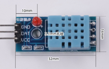
我们学习时使用的模块外观是3引脚,实际上它有4个引脚,有一个引脚是悬空的。
3.引脚示意图
如下图所示:
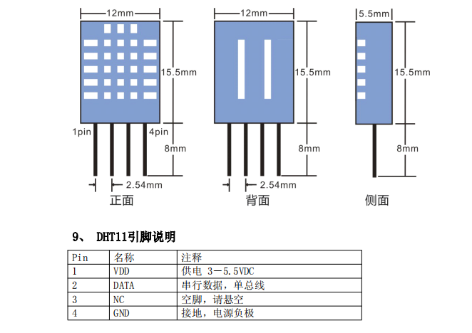
这一次学习我们使用的是PG9引脚,其他的造图上接就可以。
二、使用步骤
1.串行通信的过程
如图所示:
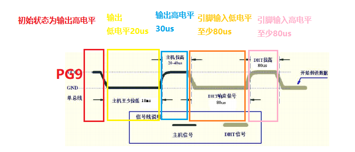

从图中我们可以清楚的看到整个通信过程,查看产品手册可以看到这样几句话
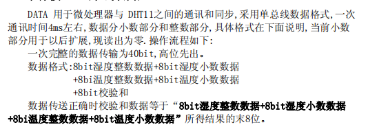
也就是说我们需要接收5个8bit的数据,最后拿前面四位和最后以为验证数据的正确性。
接下来编写通信的代码。
引脚初始化
void dht11_init(void)
{


   //使能PG9时钟
	RCC_AHB1PeriphClockCmd(RCC_AHB1Periph_GPIOG, ENABLE);

	//配置PG9为输出模式
	GPIO_InitStructure.GPIO_Pin = GPIO_Pin_9;
	GPIO_InitStructure.GPIO_Mode = GPIO_Mode_OUT;//复用功能模式
	GPIO_InitStructure.GPIO_OType = GPIO_OType_PP;//推挽输出
	GPIO_InitStructure.GPIO_Speed = GPIO_Speed_100MHz;//100MHz
	GPIO_InitStructure.GPIO_PuPd = GPIO_PuPd_NOPULL;//上拉
	GPIO_Init(GPIOG, &GPIO_InitStructure);//初始化
	//配置PE6为输入模式

	//引脚初始状态为高电平
	PGout(9)=1;
}
通信过程
int32_t dht11_read(uint8_t *pbuf)
{


	uint32_t t=0;
	int32_t i=0,j=0;
	uint8_t d=0;
	uint8_t *p=pbuf;
	uint32_t check_sum=0;

	GPIO_InitStructure.GPIO_Pin = GPIO_Pin_9;
	GPIO_InitStructure.GPIO_Mode = GPIO_Mode_OUT;//复用功能模式
	GPIO_InitStructure.GPIO_OType = GPIO_OType_PP;//推挽输出
	GPIO_InitStructure.GPIO_Speed = GPIO_Speed_100MHz;//100MHz
	GPIO_InitStructure.GPIO_PuPd = GPIO_PuPd_NOPULL;//上拉
	GPIO_Init(GPIOG, &GPIO_InitStructure);//初始化

	PGout(9)=0;
	delay_ms(20);
	PGout(9)=1;
	delay_us(30);

	GPIO_InitStructure.GPIO_Pin = GPIO_Pin_9;
	GPIO_InitStructure.GPIO_Mode = GPIO_Mode_IN;//复用功能模式
	GPIO_InitStructure.GPIO_Speed = GPIO_Speed_100MHz;//100MHz
	GPIO_InitStructure.GPIO_PuPd = GPIO_PuPd_NOPULL;//上拉
	GPIO_Init(GPIOG, &GPIO_InitStructure);//初始化

	//等待低电平出现
	t=0;
	while(PGin(9))
	{


		//超时处理
		t++;
		delay_us(1);
		if(t>=4000)
		{


			return -1;
		}
	}

	//检验低电平的合法性
	t=0;
	while(PGin(9)==0)
	{


		t++;
		delay_us(1);
		if(t>=4000)
		{


			return -2;
		}
	}

	t=0;
	while(PGin(9))
	{


		t++;
		delay_us(1);
		if(t>=4000)
		{


			return -3;
		}
	}
	for(j=0;j<5;j++)
	{


		d=0;
		for(i=7;i>=0;i--)
		{


			t=0;
			while(PGin(9)==0)
			{


				t++;
				delay_us(1);
				if(t>=4000)
				{


					return -4;
				}

			}
			delay_us(40);
			//判断当前引脚电平
			if(PGin(9))
			{


				d|=1<<i;

				//等待高电平完毕
				t=0;
				while(PGin(9))
				{


					t++;
					delay_us(1);
					if(t>=1000)
					{


						return -5;
					}
				}
			}

		}
		p[j]=d;

	}
	//校验和
	check_sum = (p[0]+p[1]+p[2]+p[3])&0xFF;

	if(p[4]!=check_sum)
	{


		return -6;

	}
	return 0;

}
2.完整代码
代码如下:
#include "stm32f4xx.h"                  // Device header
#include "sys.h"
#include "stdio.h"


static GPIO_InitTypeDef  GPIO_InitStructure;
static USART_InitTypeDef USART_InitStructure;
static NVIC_InitTypeDef NVIC_InitStructure;
static uint16_t d;


struct __FILE {

     int handle; /* Add whatever you need here */ };
FILE __stdout;
FILE __stdin;
int fputc(int ch, FILE *f)
{


	USART_SendData(USART1,ch);
	while(USART_GetFlagStatus(USART1,USART_FLAG_TXE)==RESET);

	return ch;
}


void delay_ms(uint32_t n)
{


	while(n--)
	{


		SysTick->CTRL = 0; // Disable SysTick
		SysTick->LOAD = (168000)-1; // Count from 255 to 0 (256 cycles)
		SysTick->VAL = 0; // Clear current value as well as count flag
		SysTick->CTRL = 5; // Enable SysTick timer with processor clock
		while ((SysTick->CTRL & 0x00010000)==0);// Wait until count flag is set
	}

	SysTick->CTRL = 0; // Disable SysTick
}
void delay_us(uint32_t n)
{


	while(n--)
	{


		SysTick->CTRL = 0; // Disable SysTick
		SysTick->LOAD = (168)-1; // Count from 255 to 0 (256 cycles)
		SysTick->VAL = 0; // Clear current value as well as count flag
		SysTick->CTRL = 5; // Enable SysTick timer with processor clock
		while ((SysTick->CTRL & 0x00010000)==0);// Wait until count flag is set
	}

	SysTick->CTRL = 0; // Disable SysTick
}

void usart1_init(uint32_t band)
{


	//打开硬件时钟
	RCC_AHB1PeriphClockCmd(RCC_AHB1Periph_GPIOA, ENABLE);

	//打开串口1硬件时钟
	RCC_APB2PeriphClockCmd(RCC_APB2Periph_USART1, ENABLE);

	//配置PA9和PA10为服用功能
	GPIO_InitStructure.GPIO_Pin = GPIO_Pin_9|GPIO_Pin_10;
	GPIO_InitStructure.GPIO_Mode = GPIO_Mode_AF;//复用功能模式
	GPIO_InitStructure.GPIO_OType = GPIO_OType_PP;//推挽输出
	GPIO_InitStructure.GPIO_Speed = GPIO_Speed_100MHz;//100MHz
	GPIO_InitStructure.GPIO_PuPd = GPIO_PuPd_UP;//上拉
	GPIO_Init(GPIOA, &GPIO_InitStructure);//初始化


	//将PA9和PA10引脚连接到串口1的硬件
	GPIO_PinAFConfig(GPIOA,GPIO_PinSource9,GPIO_AF_USART1);
	GPIO_PinAFConfig(GPIOA,GPIO_PinSource10,GPIO_AF_USART1);

	//配置串口1相关参数:波特率、无校验位、8位数位、1位停止位
	USART_InitStructure.USART_BaudRate = band;					//波特率
    USART_InitStructure.USART_WordLength = USART_WordLength_8b; //8位数据位
    USART_InitStructure.USART_StopBits = USART_StopBits_1;		//1个停止位
    USART_InitStructure.USART_Parity = USART_Parity_No;			//无奇偶检验
    USART_InitStructure.USART_HardwareFlowControl = USART_HardwareFlowControl_None; //无硬件流控制
    USART_InitStructure.USART_Mode = USART_Mode_Rx | USART_Mode_Tx;	//允许收发数据

    USART_Init(USART1, &USART_InitStructure);

	//配置串口1的中断触发方法 接收一个字节触发中断
	USART_ITConfig(USART1, USART_IT_RXNE, ENABLE);
	//配置串口1的中断优先级

	NVIC_InitStructure.NVIC_IRQChannel = USART1_IRQn;
	NVIC_InitStructure.NVIC_IRQChannelPreemptionPriority = 0;
	NVIC_InitStructure.NVIC_IRQChannelSubPriority = 0;
	NVIC_InitStructure.NVIC_IRQChannelCmd = ENABLE;
	NVIC_Init(&NVIC_InitStructure);

	//使能串口1工作
	USART_Cmd(USART1,ENABLE);
}

void dht11_init(void)
{


   //使能PG9时钟
	RCC_AHB1PeriphClockCmd(RCC_AHB1Periph_GPIOG, ENABLE);

	//配置PG9为输出模式
	GPIO_InitStructure.GPIO_Pin = GPIO_Pin_9;
	GPIO_InitStructure.GPIO_Mode = GPIO_Mode_OUT;//复用功能模式
	GPIO_InitStructure.GPIO_OType = GPIO_OType_PP;//推挽输出
	GPIO_InitStructure.GPIO_Speed = GPIO_Speed_100MHz;//100MHz
	GPIO_InitStructure.GPIO_PuPd = GPIO_PuPd_NOPULL;//上拉
	GPIO_Init(GPIOG, &GPIO_InitStructure);//初始化
	//配置PE6为输入模式


	PGout(9)=1;
}


int32_t dht11_read(uint8_t *pbuf)
{


	uint32_t t=0;
	int32_t i=0,j=0;
	uint8_t d=0;
	uint8_t *p=pbuf;
	uint32_t check_sum=0;

	GPIO_InitStructure.GPIO_Pin = GPIO_Pin_9;
	GPIO_InitStructure.GPIO_Mode = GPIO_Mode_OUT;//复用功能模式
	GPIO_InitStructure.GPIO_OType = GPIO_OType_PP;//推挽输出
	GPIO_InitStructure.GPIO_Speed = GPIO_Speed_100MHz;//100MHz
	GPIO_InitStructure.GPIO_PuPd = GPIO_PuPd_NOPULL;//上拉
	GPIO_Init(GPIOG, &GPIO_InitStructure);//初始化

	PGout(9)=0;
	delay_ms(20);
	PGout(9)=1;
	delay_us(30);

	GPIO_InitStructure.GPIO_Pin = GPIO_Pin_9;
	GPIO_InitStructure.GPIO_Mode = GPIO_Mode_IN;//复用功能模式
	GPIO_InitStructure.GPIO_Speed = GPIO_Speed_100MHz;//100MHz
	GPIO_InitStructure.GPIO_PuPd = GPIO_PuPd_NOPULL;//上拉
	GPIO_Init(GPIOG, &GPIO_InitStructure);//初始化

	//等待低电平出现
	t=0;
	while(PGin(9))
	{


		//超时处理
		t++;
		delay_us(1);
		if(t>=4000)
		{


			return -1;
		}
	}

	//检验低电平的合法性
	t=0;
	while(PGin(9)==0)
	{


		t++;
		delay_us(1);
		if(t>=4000)
		{


			return -2;
		}
	}

	t=0;
	while(PGin(9))
	{


		t++;
		delay_us(1);
		if(t>=4000)
		{


			return -3;
		}
	}
	for(j=0;j<5;j++)
	{


		d=0;
		for(i=7;i>=0;i--)
		{


			t=0;
			while(PGin(9)==0)
			{


				t++;
				delay_us(1);
				if(t>=4000)
				{


					return -4;
				}

			}
			delay_us(40);
			//判断当前引脚电平
			if(PGin(9))
			{


				d|=1<<i;

				//等待高电平完毕
				t=0;
				while(PGin(9))
				{


					t++;
					delay_us(1);
					if(t>=1000)
					{


						return -5;
					}
				}
			}

		}
		p[j]=d;

	}
	//校验和
	check_sum = (p[0]+p[1]+p[2]+p[3])&0xFF;

	if(p[4]!=check_sum)
	{


		return -6;

	}
	return 0;

}


int main(void)
{


	int32_t rt=0;
	uint8_t buf[5]={

    0};

	usart1_init(115200);
	dht11_init();


	while(1)
	{


		rt=dht11_read(buf);

		if(rt==0)
		{


			printf("T:%d.%d,H:%d.%d\r\n",buf[2],buf[3],buf[0],buf[1]);
		}else
		{


			printf("dht11 error code %d\r\n",rt);
		}
		delay_ms(2000);
	}
}


void USART1_IRQHandler(void)
{


	//检查标志位
	if(USART_GetITStatus(USART1,USART_IT_RXNE)==SET)
	{


		d=USART_ReceiveData(USART1);

		printf(d+"");
		//清空标志位
		USART_ClearITPendingBit(USART1,USART_IT_RXNE);
	}


}
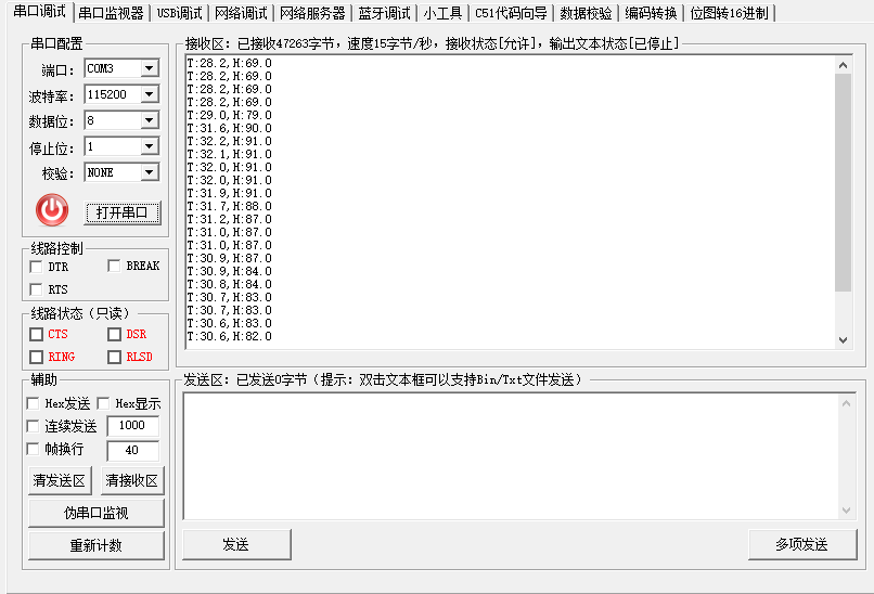
我们通过串口将数据打印到串口助手上,如果对串口不太熟悉可以下面这个介绍
基于STM32F4实现串口通信(usart)
最后我们来看看运行效果,如图所示: