本文简单介绍下手写网络调试器并连接ESP8266模块
上篇: STM32+ESP8266连接电脑Qt网络上位机——准备工作
目录
一、部分Qt代码及实现过程
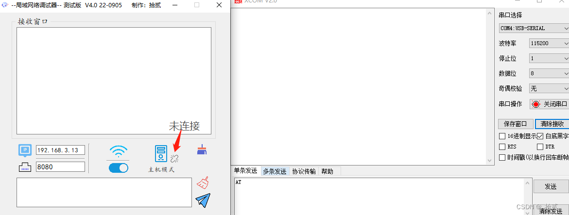
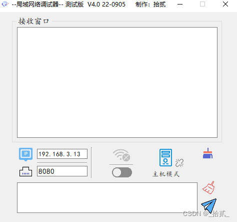
最终效果
本上位机结合了主机和服务器两种模式,在断开连接的时候可以切换模式。当作为服务器时,本机电脑的ip为该上位机的ip,可以使用ipconfig查看ip地址。最后新增了连接状态现实,以下矢量图均来自阿里。下方评论发源码->邮箱或 自行下载 Git -> https://gitee.com/guo-lingran/tcp_-server-and-client
https://gitee.com/guo-lingran/tcp_-server-and-client百度网盘下载:https://pan.baidu.com/s/1sSVkUJrMqN9fP4x1uSrDtA 提取码:qt92
代码部分
在QT中基于TCP的通信会使用到两个类:
- QTcpServer: 服务器类,用于监听客户端连接以及与客户端连接
- QTcpSocket: 客户端、服务端都需要用到
构造函数
在构造函数里添加connect操作,当有新的连接时,tcpServer会有一个newConnection的信号,将执行槽函数(newConnection_Slot())。以下都是对界面的初始化。
Widget::Widget(QWidget *parent) :
    QWidget(parent),
    ui(new Ui::Widget)
{
    ui->setupUi(this);
    tcpServer = new QTcpServer(this);
    tcpSocket = new QTcpSocket(this);

    //默认使用主机模式,等待新的连接
    connect(tcpServer,SIGNAL(newConnection()),this,SLOT(newConnection_Slot()));

    setFixedSize(480,420);
    //默认端口号 8080
    ui->portEdit->setText("8080");
    ui->ipED->setText("192.168.3.13");
    setWindowTitle("--局域网络调试器-- 测试版  V4.0 22-0905     制作:拾贰");
}
newConnection_Slot槽函数
获取到新的连接后,调用 nextPendingConnection去接收一个等待的连接,并修改界面的状态图标为”在线“状态。当tcpServer发出readyRead信号后,将接收数据,由接收槽函数(readyRead_Slot())去处理。
这里再写一个connect,若断开连接,tcpServer发出断开连接的信号,同样的去处理断联的槽函数。
void Widget::newConnection_Slot(){

    tcpSocket=tcpServer->nextPendingConnection();//得到通信的套接字对象
    connect(tcpSocket,SIGNAL(readyRead()),this,SLOT(readyRead_Slot()));
    connect(tcpSocket,SIGNAL(disconnected()),this,SLOT(disconnected_Slot()));
    //建立连接后,修改界面的状态的信息——在线的图标
    ui->label_3->setStyleSheet("border-image: url(:/new/prefix1/connect.png)");
}
readyRead_Slot槽函数
把接收到的数据全部读出来,这里防止乱码,将把收到的数据转化一下。tcpSocket->readAll()为客户端发来的数据,最后显示到接受框内。
void Widget::readyRead_Slot(){
    QByteArray receiveDate;
    QTextCodec *tc = QTextCodec::codecForName("GBK");

    while(!tcpSocket->atEnd()){
        receiveDate = tcpSocket->readAll();
    }
    if (!receiveDate.isEmpty())
    {
        QString strBuf=tc->toUnicode(receiveDate);
         ui->RecvEdit->appendPlainText(strBuf);
    }
    receiveDate.clear();
}
disconnected_Slot槽函数
断联后将关闭tcpSocket,同样的修改界面的状态图标为”离线“状态
//服务器或客户机连接状态
void Widget::disconnected_Slot(){
    tcpSocket->close();
    ui->label_3->setStyleSheet("border-image: url(:/new/prefix1/discon.png)");
}
网络监听
获取控件里的端口,调用listen接口,第一个参数,QHostAddress::Any:服务器将侦听所有网络接口,第二个参数:端口号。若当前状态为客户机,将connectToHost目标主机,创建一个connect,若有连接,执行connnect_Slot()槽函数。其余为优化界面的操作。
//打开网络/关闭网络
void Widget::on_openBt_clicked()
{
    flag_Sw=!flag_Sw;
    if(flag_Sw){
        //选择主机
        if(MS) {
            tcpServer->listen(QHostAddress::Any,ui->portEdit->text().toUInt());
        }
        else//客户机 {
            tcpSocket->connectToHost(ui->ipED->text(),ui->portEdit->text().toUInt());
            connect(tcpSocket,SIGNAL(connected()),this,SLOT(connected_Slot()));
        }
        ui->openBt->setStyleSheet("border-image: url(:/new/prefix1/open.png)");
        ui->wifi->setStyleSheet("border-image: url(:/new/prefix1/wifi_on.png)");
    }
    else{
        tcpServer->close();
        tcpSocket->close();
        ui->openBt->setStyleSheet("border-image: url(:/new/prefix1/close.png)");
        ui->wifi->setStyleSheet("border-image: url(:/new/prefix1/wifi_off.png)");
    }
}
connnect_Slot槽函数
//客户机连接
void Widget::connected_Slot(){
    connect(tcpSocket,SIGNAL(readyRead()),this,SLOT(readyRead_Slot()));
    ui->label_3->setStyleSheet("border-image: url(:/new/prefix1/connect.png)");
    connect(tcpSocket,SIGNAL(disconnected()),this,SLOT(disconnected_Slot()));
}
主机\客户机切换函数
//主副机切换
void Widget::on_ms_clicked()
{
 if(!flag_Sw){
    tcpServer->close();
    tcpSocket->close();
    if(MS){
        MS=false;
        ui->label->setText("客户机模式");
        ui->ms->setStyleSheet("border-image: url(:/new/prefix1/client.png);");
    }
    else {
        MS=true;
        ui->label->setText("主机模式");
        ui->ms->setStyleSheet("border-image: url(:/new/prefix1/server.png);");
    }
 }
 else
    QMessageBox::critical(this,"提示","请先关闭网络,再切换模式类型");
}
发送数据
通过tcpSocket接口write函数发送数据
void Widget::on_sendBt_clicked()
{
    QString SendCon =  ui->sendEdit->text().toLocal8Bit().data();
    if(flag_Sw){
        if(SendCon!=""){
            //封装编码
            QByteArray receiveDate;
            QTextCodec *tc = QTextCodec::codecForName("GBK");
            //对发送框编码
            receiveDate =  ui->sendEdit->text().toLocal8Bit().data();
            QString strBuf=tc->toUnicode(receiveDate);
            //整合符号 ->
            QString  str="->";
            QString str2 =str.append(strBuf);
             //向输出框打印发送的数据
            ui->RecvEdit->appendPlainText(str2);
            tcpSocket->write(ui->sendEdit->text().toLocal8Bit().data());
        }
        else
         QMessageBox::critical(this,"警告","不能发送空白信息");
   }
    else
         QMessageBox::critical(this,"提示","发送失败,网络尚未连接");
}
其他槽函数不再一一介绍...
二、实现过程——使用ESP8266连接上位机
工具:
CH340串口调试器
网络调试器
ESP8266(这里我将使用正点原子的ESP-12F,效果都一样)
实现目标:
用AT指令使ESP8266连接刚才的上位机,测试上位机是否好用,方便以后和STM32通信
接下来将一步一步接入网络调试器
这里上位机作为服务器,ip地址为192.168.3.13,8266作为客户机连接到电脑的热点,接入服务器
- 测试AT,返回OK,保证模块没有问题
- 打开电脑热点
3. AT+CWJAP="Lng","12345678" 连接当前的热点
4. AT+CIPSTART="TCP","192.168.3.13",8080 与服务器建立TCP连接
5. AT+CIPMODE=1 传输模式为透传
6. AT+CIPSNED 开启透传模式,向服务器发送数据
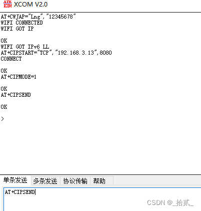
到此处8266已经连接上了网络助手,这里随便输入字符,测试结果如下:
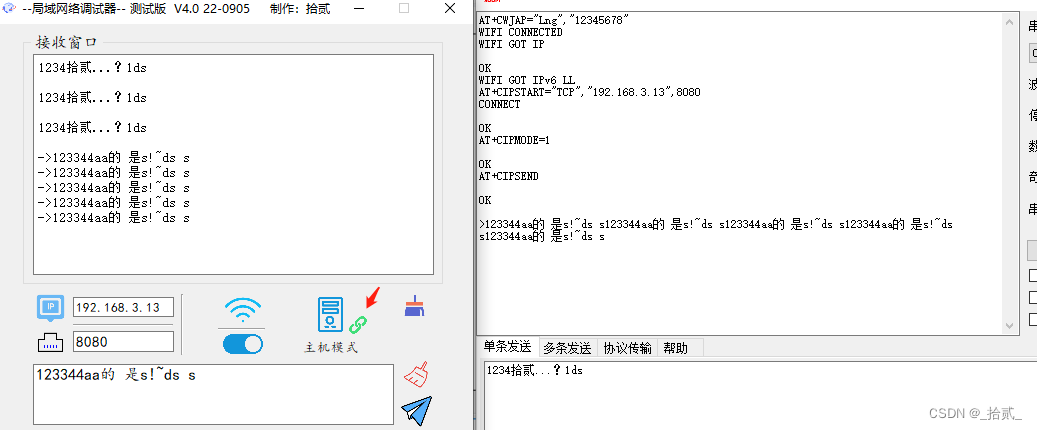
到这里呢ESP8266模块已经和此上位机正常通信了,接下来将会搭载STM32,敬请期待...