VRRP+MSTP典型组网配置
VRRP是一种容错协议,它保证当主机的下一跳路由器出现故障时,由另一台路由器来代替出现故障的路由器进行工作,从而保持网络通信的连续性和可靠性。
MSTP:多生成树协议,通过生成多个生成树,来解决以太网环路问题。
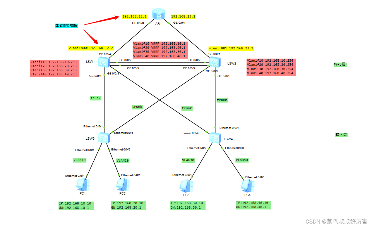
实验拓扑
一、VLAN配置
SW3配置
sy sw3
un in en
vlan batch 10 20 30 40
interface g0/0/2
 port link-type access
 port default vlan 10
 q
interface g0/0/3
 port link-type access
 port default vlan 20
SW4配置
sy sw4
un in en
vlan batch 10 20 30 40
interface g0/0/2
 port link-type access
 port default vlan 30
 q
interface g0/0/3
 port link-type access
 port default vlan 40
 q
二、Trunk配置
SW3配置
interface Ethernet0/0/1
 port link-type trunk
 port trunk allow-pass vlan 10 20

interface Ethernet0/0/4
 port link-type trunk
 port trunk allow-pass vlan 10 20
SW4配置
interface Ethernet0/0/1
 port link-type trunk
 port trunk allow-pass vlan 30 40
 q

interface Ethernet0/0/4
 port link-type trunk
 port trunk allow-pass vlan 30 40
 q
SW1配置
sy sw1
un in en
vlan batch 10 20 30 40

interface GigabitEthernet0/0/1
 port link-type trunk
 port trunk allow-pass vlan 10 20

interface GigabitEthernet0/0/3
 port link-type trunk
 port trunk allow-pass vlan 30 40
SW2配置
sy sw2
un in en
vlan batch 10 20 30 40

interface GigabitEthernet0/0/1
 port link-type trunk
 port trunk allow-pass vlan 30 40

interface GigabitEthernet0/0/3
 port link-type trunk
 port trunk allow-pass vlan 10 20
三、链路聚合
SW1和SW2之间我们用两根网线,做成链路聚合。
SW1配置
[hxsw1]int Eth-Trunk 1
[hxsw1-Eth-Trunk1]mode lacp-static
[hxsw1-Eth-Trunk1]trunkport g0/0/2
Info: This operation may take a few seconds. Please wait for a moment...done.
[hxsw1-Eth-Trunk1]trunkport g0/0/5
Info: This operation may take a few seconds. Please wait for a moment...done.
SW2配置
[hxsw2]int Eth-Trunk 1
[hxsw2-Eth-Trunk1]mode lacp-static
[hxsw2-Eth-Trunk1]trunkport g0/0/2
Info: This operation may take a few seconds. Please wait for a moment...done.
[hxsw2-Eth-Trunk1]trunkport g0/0/5
Info: This operation may take a few seconds. Please wait for a moment...done.
[hxsw2-Eth-Trunk1]
验证查看:
[hxsw1]dis eth-trunk
Eth-Trunk1's state information is:
Local:
LAG ID: 1                   WorkingMode: STATIC
Preempt Delay: Disabled     Hash arithmetic: According to SIP-XOR-DIP
System Priority: 32768      System ID: 4c1f-cc6a-6dff
Least Active-linknumber: 1  Max Active-linknumber: 8
Operate status: up          Number Of Up Port In Trunk: 2
--------------------------------------------------------------------------------
ActorPortName          Status   PortType PortPri PortNo PortKey PortState Weight
GigabitEthernet0/0/2   Selected 1GE      32768   3      305     10111100  1
GigabitEthernet0/0/5   Selected 1GE      32768   6      305     10111100  1

Partner:
--------------------------------------------------------------------------------
ActorPortName          SysPri   SystemID        PortPri PortNo PortKey PortState
GigabitEthernet0/0/2   32768    4c1f-ccb4-3bac  32768   3      305     10111100
GigabitEthernet0/0/5   32768    4c1f-ccb4-3bac  32768   6      305     10111100

[hxsw1]
配置trunk,允许所有vlan通过
sw1
[sw1]int Eth-Trunk 1
[sw1-Eth-Trunk1]port link-type trunk
[sw1-Eth-Trunk1]port trunk allow-pass vlan 10 20 30 40
sw2
[sw2]int Eth-Trunk 1
[sw2-Eth-Trunk1]port link-type trunk
[sw2-Eth-Trunk1]port trunk allow-pass vlan 10 20 30 40
四、MSTP配置
公共配置
以下步骤必须在所有的有冗余的交换机上做,我们没有汇聚就算了,但是我们接入交换机有冗余所以要做。
stp region-configuration
 region-name pokes01    #域名pokes01
 revision-level 1       #修订好统一为1
 instance 1 vlan 10 20  #将vlan10/20映射到实例1里面
 instance 2 vlan 30 40
 active region-configuration  #激活才能生效
 q
纯净版便于复制
stp region-configuration
 region-name pokes01
 revision-level 1
 instance 1 vlan 10 20
 instance 2 vlan 30 40
 active region-configuration
 q
SW1配置
stp instance 1 root primary 	 #将SW1作为实例1的根桥
stp instance 2 root secondary    #将SW1作为实例2的备份根桥
SW2配置
stp instance 1 root secondary
stp instance 2 root primary
分别在SW3、SW4上面验证
SW3配置
在下面的查看中,我们看不到实例2,那是因为我们在SW3的trunk没有允许VLAN30/40通过
<sw3>dis stp brief
 MSTID  Port                        Role  STP State     Protection
   0    Ethernet0/0/1               ALTE  DISCARDING      NONE
   0    Ethernet0/0/2               DESI  FORWARDING      NONE
   0    Ethernet0/0/3               DESI  FORWARDING      NONE
   0    Ethernet0/0/4               ROOT  FORWARDING      NONE
   1    Ethernet0/0/1               ROOT  FORWARDING      NONE
   1    Ethernet0/0/2               DESI  FORWARDING      NONE
   1    Ethernet0/0/3               DESI  FORWARDING      NONE
   1    Ethernet0/0/4               ALTE  DISCARDING      NONE
SW4配置
在下面的查看中,我们看不到实例1,那是因为我们在SW3的trunk没有允许VLAN10/20通过
<sw4>dis stp brief
 MSTID  Port                        Role  STP State     Protection
   0    Ethernet0/0/1               DESI  FORWARDING      NONE
   0    Ethernet0/0/2               DESI  FORWARDING      NONE
   0    Ethernet0/0/3               DESI  FORWARDING      NONE
   0    Ethernet0/0/4               DESI  FORWARDING      NONE
   2    Ethernet0/0/1               ROOT  FORWARDING      NONE
   2    Ethernet0/0/2               DESI  FORWARDING      NONE
   2    Ethernet0/0/3               DESI  FORWARDING      NONE
   2    Ethernet0/0/4               ALTE  DISCARDING      NONE
五、VRRP配置
sw1配置
interface Vlanif10
 ip address 192.168.10.253 255.255.255.0
 vrrp vrid 10 virtual-ip 192.168.10.1
 vrrp vrid 10 priority 120

interface Vlanif20
 ip address 192.168.20.253 255.255.255.0
 vrrp vrid 20 virtual-ip 192.168.20.1
  vrrp vrid 20 priority 120

 interface Vlanif30
 ip address 192.168.30.253 255.255.255.0
 vrrp vrid 30 virtual-ip 192.168.30.1

 interface Vlanif40
 ip address 192.168.40.253 255.255.255.0
 vrrp vrid 40 virtual-ip 192.168.40.1
sw2配置
interface Vlanif10
 ip address 192.168.10.254 255.255.255.0
 vrrp vrid 10 virtual-ip 192.168.10.1

interface Vlanif20
 ip address 192.168.20.254 255.255.255.0
 vrrp vrid 20 virtual-ip 192.168.20.1

interface Vlanif30
 ip address 192.168.30.254 255.255.255.0
 vrrp vrid 30 virtual-ip 192.168.30.1
 vrrp vrid 30 priority 120

interface Vlanif40
 ip address 192.168.40.254 255.255.255.0
 vrrp vrid 40 virtual-ip 192.168.40.1
 vrrp vrid 40 priority 120
[sw1]dis ip in b
*down: administratively down
^down: standby
(l): loopback
(s): spoofing
The number of interface that is UP in Physical is 7
The number of interface that is DOWN in Physical is 1
The number of interface that is UP in Protocol is 6
The number of interface that is DOWN in Protocol is 2

Interface                         IP Address/Mask      Physical   Protocol
MEth0/0/1                         unassigned           down       down
NULL0                             unassigned           up         up(s)
Vlanif1                           unassigned           up         down
Vlanif10                          192.168.10.253/24    up         up
Vlanif20                          192.168.20.253/24    up         up
Vlanif30                          192.168.30.253/24    up         up
Vlanif40                          192.168.40.253/24    up         up
检测验证
<sw1>dis vrrp brief
VRID  State        Interface                Type     Virtual IP
----------------------------------------------------------------
10    Master       Vlanif10                 Normal   192.168.10.1
20    Master       Vlanif20                 Normal   192.168.20.1
30    Backup       Vlanif30                 Normal   192.168.30.1
40    Backup       Vlanif40                 Normal   192.168.40.1
----------------------------------------------------------------
Total:4     Master:2     Backup:2     Non-active:0
[sw2]dis vrrp brief
VRID  State        Interface                Type     Virtual IP
----------------------------------------------------------------
10    Backup       Vlanif10                 Normal   192.168.10.1
20    Backup       Vlanif20                 Normal   192.168.20.1
30    Master       Vlanif30                 Normal   192.168.30.1
40    Master       Vlanif40                 Normal   192.168.40.1
----------------------------------------------------------------
Total:4     Master:2     Backup:2     Non-active:0
六、VRRP+MSTP的注意事项
- 拓扑图中所有的交换机都要创建vlan10/20/30/40
- sw1和sw2之间的聚合链路,两头都要配置。
七、路由器配置
SW1
vlan 800
interface GigabitEthernet0/0/4
 port link-type access
 port default vlan 800
int vlanif800
 ip add 192.168.12.2 24
 q
SW2
vlan 801
interface GigabitEthernet0/0/4
 port link-type access
 port default vlan 801
interface Vlanif801
 ip address 192.168.23.2 255.255.255.0
 q
R1
[Huawei]sysname R1
[R1]un in en
[R1]in g0/0/0
[R1-GigabitEthernet0/0/0]ip add 192.168.12.1 24

[R1]in g0/0/1
[R1-GigabitEthernet0/0/1]ip add 192.168.23.1 24
[R1-GigabitEthernet0/0/1]q
[R1]q
八、加路由
分别在sw1、sw2上加入上外网的默认路由
[sw1]ip route-static 0.0.0.0 0 192.168.12.1
[sw2]ip route-static 0.0.0.0 0 192.168.23.1
R1加回执路由
[ar1]ip route-static 192.168.0.0 16 192.168.12.2
[ar1]ip route-static 192.168.0.0 16 192.168.23.2
这里我比较懒,手动优化了一下路由,因此改为192.168.0.0/16
九、BGP跟踪的配置
作用:当设备假死的时候,我们使它能够自动切换。
[sw1]bfd      #启用
[sw1-bfd]q
[sw1]bfd szpr01 bind peer-ip 192.168.12.1 source-ip 192.168.12.2 auto
[sw1-bfd-session-szpr01]commit
- szpr01是我起的名字
- peer-ip是对端地址
- source-ip是本地地址
[R1]bfd
[R1-bfd]q
[R1]bfd szpr01 bind peer-ip 192.168.12.2 source-ip 192.168.12.1 auto
[R1-bfd-session-szpr02]commit
注意:在这里szpr01的名字,要和SW1上一致。
查看
[sw1]dis bfd session all
--------------------------------------------------------------------------------
Local Remote     PeerIpAddr      State     Type        InterfaceName
--------------------------------------------------------------------------------

8192  0          192.168.12.1    Down      S_AUTO_PEER       -
--------------------------------------------------------------------------------
Total UP/DOWN Session Number : 0/1
未完,后续继续会扩大拓扑