目录
1. 前言
近期在学习EDA课程,课上学习了一部分关于使用Verilog语言实现求两个数的最大公约数的算法,课后在完成作业的时候看到了一篇关于在ZYBO Z7实现四位全加器的博客,于是参考该代码的输入及显示方式,实现了使用ZYBO Z7来计算最大公约数的功能,但是ZYBOZ7开发板的拨码只有4个,所以只能计算2个4位数的最大公约数。
部分参考程序:
四位全加器的FPGA实现_hfutstudenthuang的博客-CSDN博客_fpga四位加法器
2. 运行环境
1. 软件:vivado 2018.3
2. FPGA开发板:ZYBO Z7
3.实现原理
最大公约数的算法流程图如下:
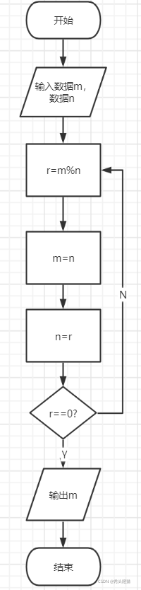
在以上过程中,存在使用除法求余数的步骤。用硬件实现除法开销较大,所以使用减法来实现,除法取余数本质上是不断做减法直到被除数小于除数。
4. 实现过程
RTL图如下:

其中共包括4个模块,即
输入模块:通过FPGA上的拨码即按钮进行两个数据的输入,以及使用开关控制结果出输出及复位。
状态机模块:规模较小的数字系统/子系统的控制逻辑一般采用状态机来实现。根据需求,对应的计算过程可以分为等待输入、计算、等待输出等三步。
计算模块:计算过程。
显示模块:通过LED灯来显示输入数据、运算结果。
5. 代码
顶层代码
`timescale 1ns/100ps//时间精度
//定义值
`define A_SEL_X   2'bxx
`define A_SEL_IN  2'b00
`define A_SEL_B   2'b01
`define A_SEL_SUB 2'b10
`define B_SEL_X   1'bx
`define B_SEL_IN  1'b0
`define B_SEL_A   1'b1
//顶层模块
module gcd_rtl_top #(parameter W=4)(
  input		clk,                   //时钟信号
  input		reset,                 //复位信号
  input wire bottom1,              //开关(控制数据1输入)
  input wire bottom2,              //开关2(控制数据2输入)
  input wire bottom3,              //开关3(控制输出结果)
  input wire [W-1:0] data,         //当前的数据
  output wire [3:0] display_result,//输出结果
  output    result_rdy              //运算状态
);

	//定义中间数据类型
	wire [W-1:0] result_data;      //运算结果
	wire   A_en;
	wire   B_en;
	wire [1:0] A_sel;
	wire   B_sel;
	wire   B_zero;
	wire   A_lt_B;
	wire [W-1:0] operand_A;        //数据1
	wire [W-1:0] operand_B;        //数据2

//调用子模块
//输入模块
data_in data_in(
	.clk(clk),
	.reset(reset),
	.bottom1(bottom1),
	.bottom2(bottom2),
	.data(data),
	.operand_A(operand_A),
	.operand_B(operand_B)
	);

	//状态机模块
gcdGCDUnitCtrl gcdUC(
    .clk(clk),
    .reset(reset),
    .A_en(A_en),
    .B_en(B_en),
    .A_sel(A_sel),
    .B_sel(B_sel),
    .result_rdy(result_rdy),
    .B_zero(B_zero),
    .A_lt_B(A_lt_B)
    );

    //计算模块
gcdGCDUnitDpath gcdUD(
    .clk(clk),
    .operand_A(operand_A),
    .operand_B(operand_B),
    .result_data(result_data),
    .A_en(A_en),
    .B_en(B_en),
    .A_sel(A_sel),
    .B_sel(B_sel),
    .B_zero(B_zero),
    .A_lt_B(A_lt_B)
    );

    //显示模块
display display(
	.clk(clk),
	.reset(reset),
	.bottom1(bottom1),
	.bottom2(bottom2),
	.bottom3(bottom3),
    .result_data(result_data),
	.display_result(display_result),
	.result_rdy(result_rdy),
	.data(data)
	);
endmodule
输入模块
`timescale 1ns / 1ps
//定义输入/输出
module data_in(
				input clk,
				input reset,
				input bottom1,
				input bottom2,
				input [3:0] data,
				output reg[3:0] operand_A=1,
				output reg[3:0] operand_B=1
			);

	always @(posedge clk or posedge reset)begin
		if(reset)                              //按下复位键时数据1,2都为0.
			begin
				operand_A<= 0;
				operand_B<= 0;
			end
		else
			begin
				if(bottom1)                    //bottom1按下时,数据1接收当前输入数据
					begin
						operand_A <= data;
					end
				else if(bottom2)               //bottom2按下时,数据2接收当前输入数据
					begin
						operand_B <= data;
					end
			end
	end
endmodule
状态机模块
`timescale 1ns/100ps
`define A_SEL_X   2'bxx
`define A_SEL_IN  2'b00
`define A_SEL_B   2'b01
`define A_SEL_SUB 2'b10
`define B_SEL_X   1'bx
`define B_SEL_IN  1'b0
`define B_SEL_A   1'b1
module gcdGCDUnitCtrl
#(parameter W = 4)//数据位数
  (
  input		clk,
  input		reset,
  input		B_zero,
  input		A_lt_B,
  output reg	A_en,
  output reg	B_en,
  output reg [1:0]	A_sel,
  output reg	B_sel,
  output reg	result_rdy
);
	localparam WAIT = 2'd0;
	localparam CALC = 2'd1;
	localparam DONE = 2'd2;            //三种状态
	reg  [1:0] state_next;             //下次状态
	wire [1:0] state;                  //当前状态
  //复位信号
	vcRDFF_pf state_pf
	( .clk     (clk),
	  .reset_p (reset),
	  .d_p     (state_next),
	  .q_np    (state)
	);

	always @(*)
	   begin
	  //控制信号
	    A_sel    = `A_SEL_X;             //定义初始值
	    A_en     = 1'b0;
	    B_sel    = `B_SEL_X;
	    B_en     = 1'b0;
	    result_rdy   = 1'b0;             //表示计算未结束
	  case ( state )
		WAIT:
		  begin                    //位于WAIT状态,读取数据
				A_sel = `A_SEL_IN;
				A_en  = 1'b1;
				B_sel = `B_SEL_IN;
				B_en = 1'b1;
		  end
		CALC:                      //位于计算状态
		  begin
			if ( A_lt_B )          //当A_lt_B=1时
			     begin
				    A_sel = `A_SEL_B;
				    A_en     = 1'b1;
				    B_sel = `B_SEL_A;
				    B_en      = 1'b1;
			     end
			else if ( !B_zero )      //当B_zero不为0时
			     begin
				    A_sel = `A_SEL_SUB;
				    A_en      = 1'b1;
			     end
          end
		DONE: result_rdy = 1'b1;      //位于计算结束状态
	  endcase
	end

	always @(*)                         //运算过程
	begin
	  state_next = state;              // 默认保持当前状态
	 case ( state )
	    WAIT :
		state_next = CALC;
	    CALC :
	      if ( B_zero) begin
		state_next = DONE;
		end
	    DONE :
		state_next = WAIT;
		endcase
end
endmodule
`timescale 1ns / 1ps
module vcRDFF_pf
(	input clk,
	input reset_p,
	input[1:0] d_p,
	output reg[1:0] q_np
);
	localparam WAIT = 2'd0;
	localparam CALC = 2'd1;
	localparam DONE = 2'd2;

always @( posedge clk or posedge reset_p )
begin
    if( reset_p )                   //当复位为1时,状态为WAIT
        q_np <= WAIT;
    else
        q_np <= d_p;                //当复位为0时,状态为下一状态
end

endmodule
计算模块
module gcdGCDUnitDpath #(parameter W = 4)
( input      clk,
  input  [W-1:0] operand_A,
  input  [W-1:0] operand_B,
  output [W-1:0] result_data,
  input          A_en,
  input          B_en,
  input    [1:0] A_sel,
  input          B_sel,
  output         B_zero,
  output         A_lt_B
);
	wire [W-1:0] B;
	wire [W-1:0] sub_out;
	wire [W-1:0] A_out;
        // 3-1多路复用器
	vcMux3#(W) A_mux
	( .in0 (operand_A),
	  .in1 (B),
	  .in2 (sub_out),
	  .sel (A_sel),
	  .out (A_out)   );
	wire [W-1:0] A;
        // register with enable
	vcEDFF_pf#(W) A_pf
	( .clk  (clk),
	  .en_p (A_en),
	  .d_p  (A_out),
	  .q_np (A)      );

	wire [W-1:0] B_out;

        // 2-1多路复用器
	vcMux2#(W) B_mux
	( .in0 (operand_B),
	  .in1 (A),
	  .sel (B_sel),
	  .out (B_out)    );

        // register with enable
	vcEDFF_pf#(W) B_pf
	( .clk  (clk),
	  .en_p (B_en),
	  .d_p  (B_out),
	  .q_np (B)      );

	assign B_zero  = (B==0);
	assign A_lt_B  = (A < B);
	assign sub_out = A - B;
	assign result_data = A;
endmodule
`timescale 1ns/100ps
`define A_SEL_X   2'bxx
`define A_SEL_IN  2'b00
`define A_SEL_B   2'b01
`define A_SEL_SUB 2'b10
`define B_SEL_X   1'bx
`define B_SEL_IN  1'b0
`define B_SEL_A   1'b1
module vcMux3 #(parameter W = 4)
(
	input[W-1:0] in0,
	input[W-1:0] in1,
	input[W-1:0] in2,
	input[1:0] sel,
	output reg[W-1:0] out
);

	always @(*)
	begin
		case(sel)
		`A_SEL_IN : out <= in0;
		`A_SEL_B : out <= in1;
		`A_SEL_SUB : out <= in2;
		endcase
	end
endmodule
`timescale 1ns/100ps
`define A_SEL_X 2'bxx
`define A_SEL_IN 2'b00
`define A_SEL_B 2'b01
`define A_SEL_SUB 2'b10
`define B_SEL_X 1'bx
`define B_SEL_IN 1'b0
`define B_SEL_A 1'b1
module vcMux2 #(parameter W = 4)
(
input [W-1:0] in0,
input [W-1:0] in1,
input sel,
output reg[W-1:0] out
);
always @(sel)
begin
case(sel)
`B_SEL_IN : out <= in0;
`B_SEL_A : out <= in1;
endcase
end
endmodule`timescale 1ns/100ps
`define A_SEL_X 2'bxx
`define A_SEL_IN 2'b00
`define A_SEL_B 2'b01
`define A_SEL_SUB 2'b10
`define B_SEL_X 1'bx
`define B_SEL_IN 1'b0
`define B_SEL_A 1'b1
module vcEDFF_pf #(parameter W = 4)
(
input clk,
input en_p,
input[W-1:0] d_p,
output reg[W-1:0] q_np
);
always @(posedge clk)
begin
if(en_p) begin
q_np <= d_p;
end
end
endmodule显示模块
`timescale 1ns / 1ps
module display(
		input clk,
		input reset,
		input bottom1,
		input bottom2,
		input bottom3,
		input carry_out,
		input [3:0] result_data,
		output reg [3:0] display_result,
		input result_rdy,
		input [3:0] data
				);
	always @(posedge clk or posedge reset)
	begin
		if(reset)                                     //按下复位键,输出清0
			begin
				display_result <= 0;
			end
		else
			begin
				if(bottom3&result_rdy)                  //bottom3按下时,显示求和结果以及进位输出
					begin
						display_result <= result_data;
					end
				else if(bottom1)                        //bottom1按下时,显示输入数据
					begin
						display_result <=data;
					end
				else if(bottom2)                        //bottom2按下时,显示输入数据
					begin
						display_result <= data;
					end
			end
	end
endmodule
约束文件
##Clock signal
set_property -dict { PACKAGE_PIN K17   IOSTANDARD LVCMOS33 } [get_ports { clk }];
create_clock -add -name sys_clk_pin -period 8.00 -waveform {0 4} [get_ports { clk }];

##Switches
set_property -dict { PACKAGE_PIN G15   IOSTANDARD LVCMOS33 } [get_ports { data[0] }];
set_property -dict { PACKAGE_PIN P15   IOSTANDARD LVCMOS33 } [get_ports { data[1] }];
set_property -dict { PACKAGE_PIN W13   IOSTANDARD LVCMOS33 } [get_ports { data[2] }];
set_property -dict { PACKAGE_PIN T16   IOSTANDARD LVCMOS33 } [get_ports { data[3] }];

##Buttons
set_property -dict { PACKAGE_PIN K18   IOSTANDARD LVCMOS33 } [get_ports { reset }];
set_property -dict { PACKAGE_PIN P16   IOSTANDARD LVCMOS33 } [get_ports { bottom1 }];
set_property -dict { PACKAGE_PIN K19   IOSTANDARD LVCMOS33 } [get_ports { bottom2 }];
set_property -dict { PACKAGE_PIN Y16   IOSTANDARD LVCMOS33 } [get_ports { bottom3 }];

##LEDs
set_property -dict { PACKAGE_PIN M14   IOSTANDARD LVCMOS33 } [get_ports { display_result[0] }];
set_property -dict { PACKAGE_PIN M15   IOSTANDARD LVCMOS33 } [get_ports { display_result[1] }];
set_property -dict { PACKAGE_PIN G14   IOSTANDARD LVCMOS33 } [get_ports { display_result[2] }];
set_property -dict { PACKAGE_PIN D18   IOSTANDARD LVCMOS33 } [get_ports { display_result[3] }];

##RGB LED 5
set_property -dict { PACKAGE_PIN Y11   IOSTANDARD LVCMOS33 } [get_ports { result_rdy }];
6. 功能仿真
编写仿真文件:
`timescale 1ns / 1ps
module gcd_rtl_test;
parameter W = 4;
reg clk = 0;
reg reset = 1;
reg bottom1;
reg bottom2;
reg bottom3;
reg [W-1:0] data;
wire [W-1:0] display_result;
gcd_rtl_top #(4) gcd_rtl(
  .clk(clk),
  .reset(reset),
  .bottom1(bottom1),
  .bottom2(bottom2),
  .bottom3(bottom3),
  .display_result(display_result),
  .data(data)
);
always #10 clk =~clk;
  initial begin
  clk <= 0;
			reset <= 1;
			bottom1 <= 0;
			bottom2 <= 0;
			bottom3 <= 0;
    #20 reset = 0;
    #20 bottom1<=1;
        data <= 4'd6;
    #20 bottom1<=0;
        bottom2<=1;
        data<= 4'd9;
    #20 bottom1<=0;
        bottom2<=0;
    #20
	    bottom3 <= 1;
  end

endmodule
点击run simulation仿真结果如下:

当bottom1按下时,显示结果为6,即第一个输入。
当bottom2按下时,显示结果为9,即第二个输入。
当bottom3按下时,显示为3,运算正确。
7. 结果
点击generate bitstream生成比特流文件;
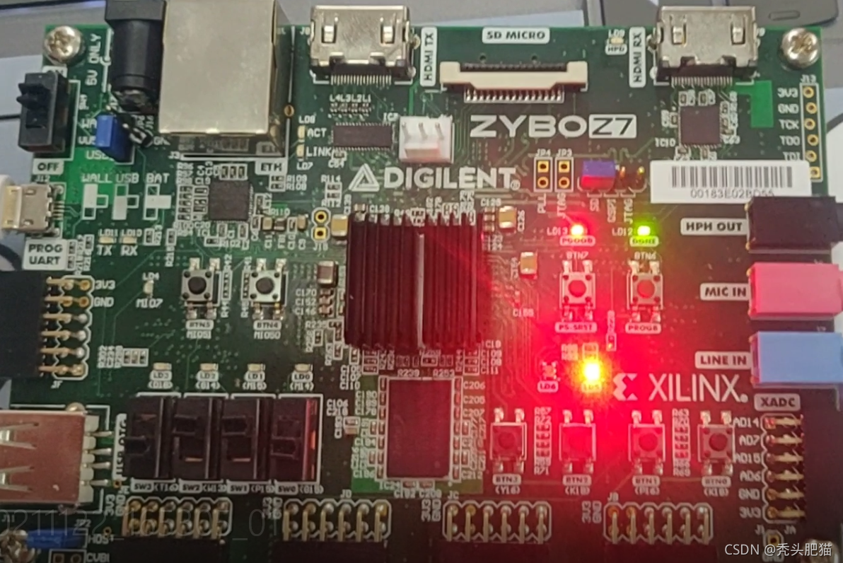
将zybo z7连接电脑,之后点击open hardware manager,点击open target - auto connect。最后将比特流文件烧录进ZYBO Z7。绿灯亮起,即可以正常使用功能。
拨动开关输入数据4'b 0110(6),按下右下角从右向左第二个开关(即bottom1),显示0110.

拨动开关输入数据4'b 1001(9),按下右下角从右向左第三个开关(即bottom2),显示1001.

按下右下角从右向左第四个开关(即bottom3),显示结果0011(3)。
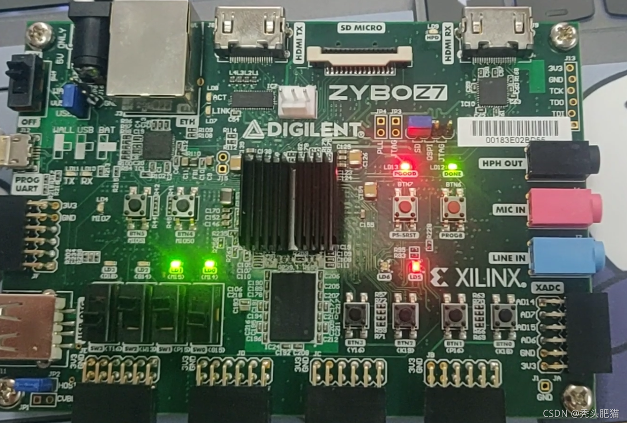
按下右下角从右向左第一个开关(即reset),显示归0.